Week 9 - Challenge 3 - Bumper
AIM: -
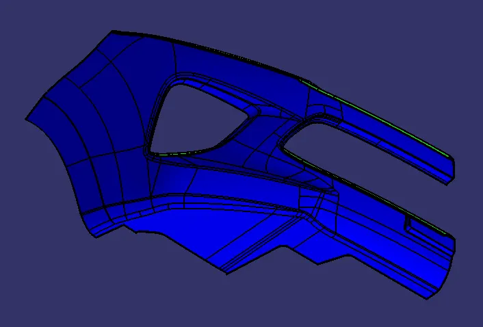
- Create the Bumper Plastic component through the given Class-A surface.
- The tooling axis for the given Class-A Surface should be created to meet the requirements of the draft angle.
- Create CLASS B and CLASS C Surface.
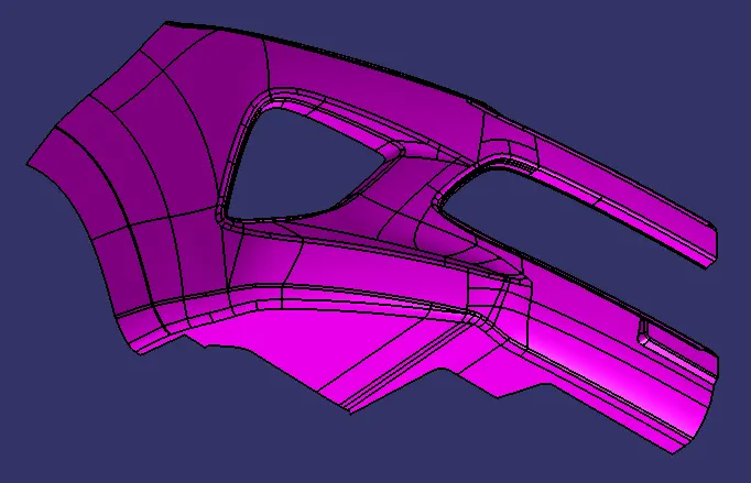
- Perform the Draft analysis on the model.
GIVEN CLASS-A SURFACE
CREATION OF TOOLING AXIS
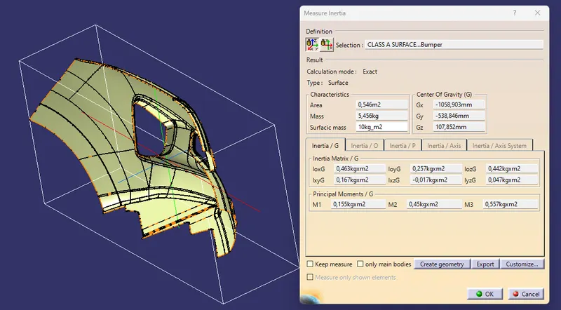
- Choose the A-surface and then click "Measure inertia."
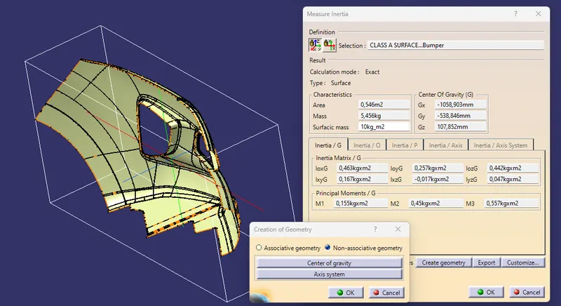
- In the Measure Inertia box, select "Create geometry.
- Choose Non-associative geometry in the Creation of Geometry window.
- Choose "Center of Gravity."
- The point of inertia is formed.
- The component is seen on all three axes: X, Y, and Z.
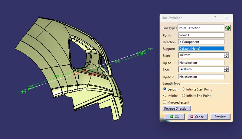
- The X-axis is found to be the direction for the Tooling axis, and a line is produced using the CG point and the X-direction as the line's direction.
DRAFT ANALYSIS OF THE CLASS A SURFACE
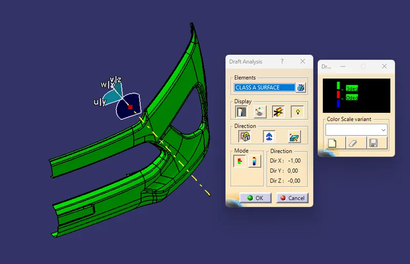
- Surface draft analysis determines whether the surface or item can be fabricated with the appropriate draft angle.
- Because the component would have shrunk towards the centre while cooling, a draught angle is required for it to clear the core and cavity surface.
- With this design, the draft angle is 3 degrees. Because A is a single surface, there will be slight colour variation.
CREATION OF CLASS-B SURFACE
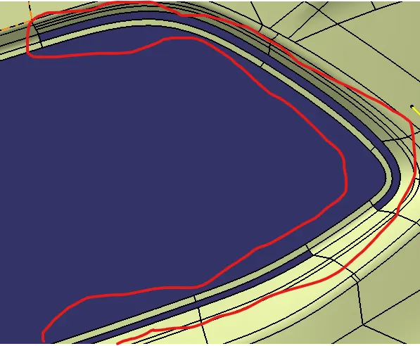
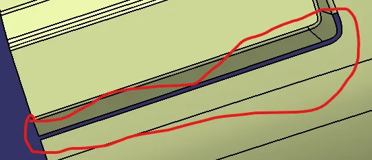
- The A-surface is offset by 3.00mm due to the requisite thickness. But found some open patches on the surface as below: -
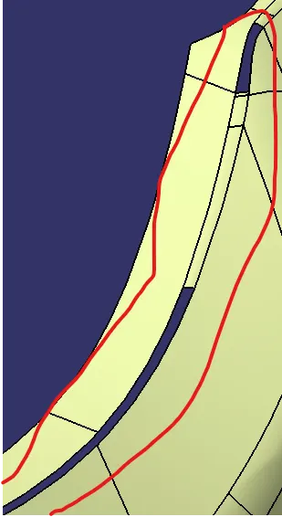
| PATCH 1 | PATCH 2 | PATCH 3 |
- Regions, where the B-surface has problems, are repaired by closing them with commands such as Multi-section, Sweep, Offset, and Multi extract.
- Lastly, all of the newly formed surfaces are trimmed or linked together with previously offset surfaces. This resulted in a single surface that would serve as the final B-surface.
- By generating a full boundary, the produced B surface is examined for any gaps or flaws.
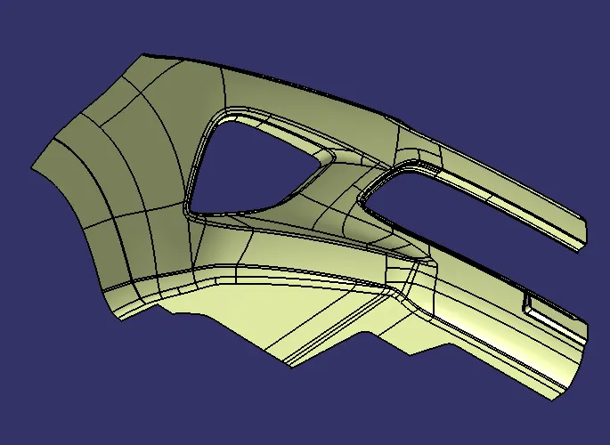
CREATION OF CLASS C SURFACE
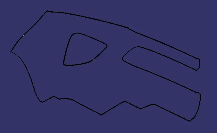
- The A and B surfaces are joined by a single surface known as the C surface.
- It is made by utilising a sweep with A as the reference surface and a curve made from the same surface's boundary.
- A-surfaces are also created by sweeping with a draft direction.
CREATION OF CLOSE BODY
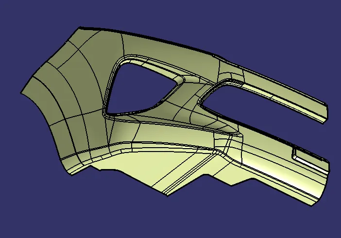
- The surfaces (A, B, C) are all connected to create a closed body.
- The boundary is chosen, and the body is chosen. Because an error occurred, it is clear that all surfaces are connected to create a suitable closed surface body.
- Lastly, in the component design workbench, the near volume is converted to a solid body.
DRAFT ANALYSIS OF SOLID BODY
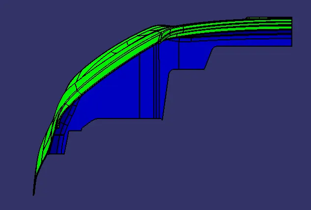
- Draft analysis must be performed on the final solid component body. This is done to ensure that all regions of the body meet the draft angle of 3 degrees.
- A draft angle is a taper given to the vertical walls of an injection-moulded component to help the item come out of the mould.
- Draft angles are a need for bespoke injection-molded products. A functioning injection moulding item must have draft angles on both the cavity and core sides. This reduces the possibility of damage to the parts and ensures that they can be removed from the machine.
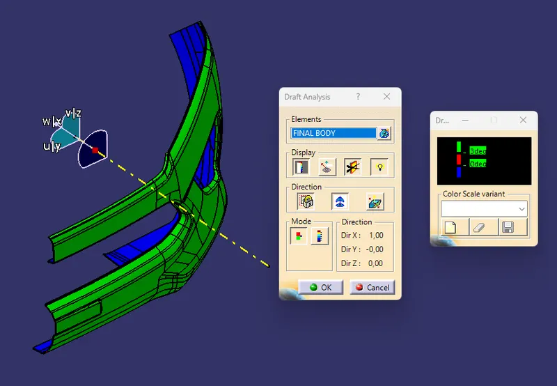
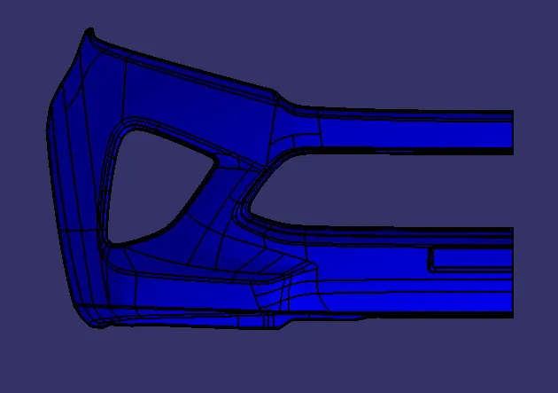
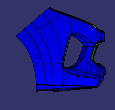
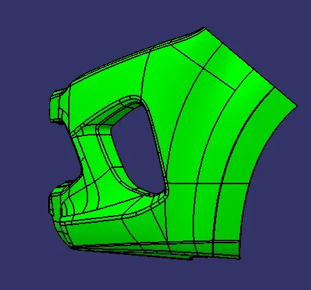
Screenshots of the solid model with the proper colour code of the draft angle in various orientations (Isometric, Front, Side, and Top View)
FRONT VIEW
RIGHT HAND SIDE VIEW
LEFT HAND SIDE VIEW
TOP VIEW
ISOMETRIC VIEW