Week 10 - Challenge 1- Attachment Feature Creation (Ribs & Screw Boss)
AIM: -
- To Create the Door Handle Component from the given Class-A surface.
- Create the tooling axis for the given Class-A Surface meeting the requirements of the draft angle.
- Attach B side Features in the component.
- Create the RIBS and SCREW BOSS for the Drill Handle considering the design rules.
- Perform the Draft analysis on the model.
PROCEDURE: -
- Creating the tooling axis
- Draft analysis of Class A surface
- Creating Class B surface
- Creating Class C surface
- Surface and solid body
- Engineering features Rib and Screw boss
- Draft analysis of Solid body
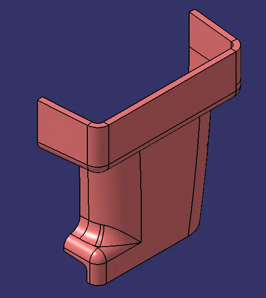
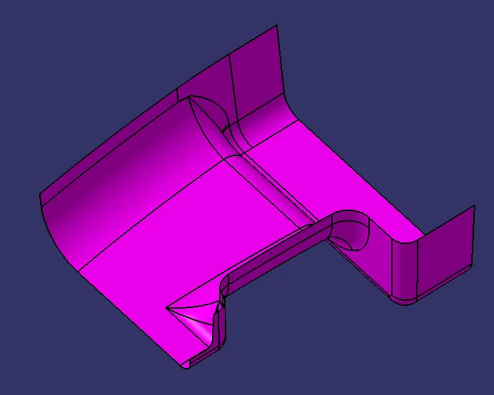
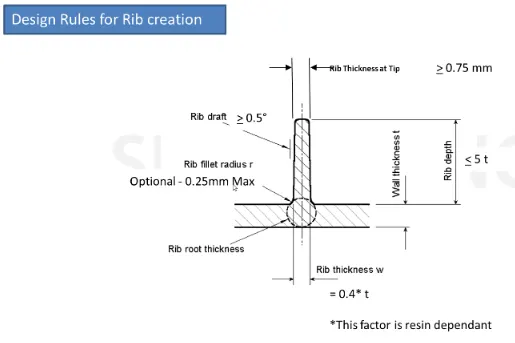
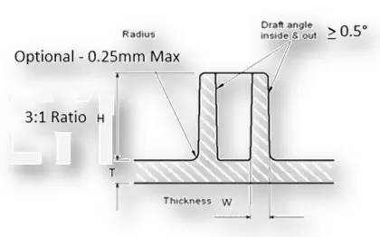
GIVEN CLASS-A SURFACE AND Design rules to follow to create the RIBS and SCREW BOSS
1. Creating of Tooling Axis
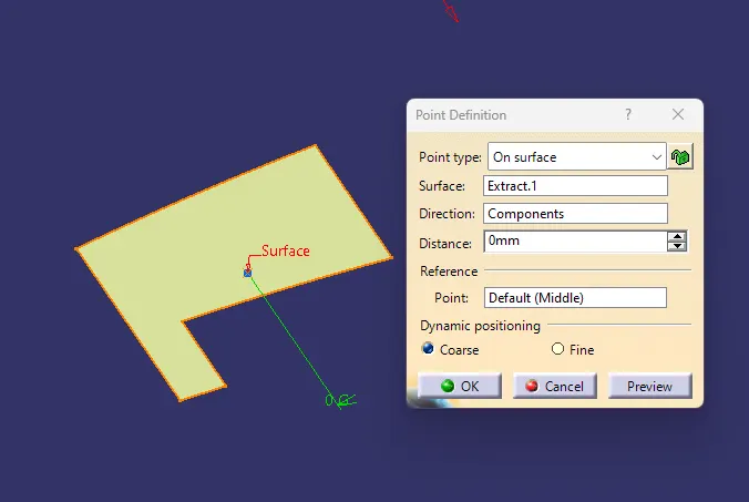
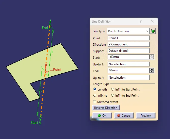
The first step is to closely examine the specified class-A surface, namely the bigger flat region perpendicular to the Tooling axis. As a result, the tooling direction for this class-A surface will be in the Y-direction. As a result, we draw the point on the flat surface as shown in the image.
2. Draft analysis of Class A surface
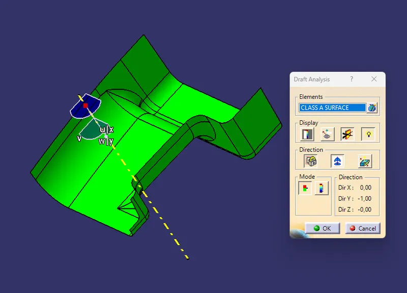
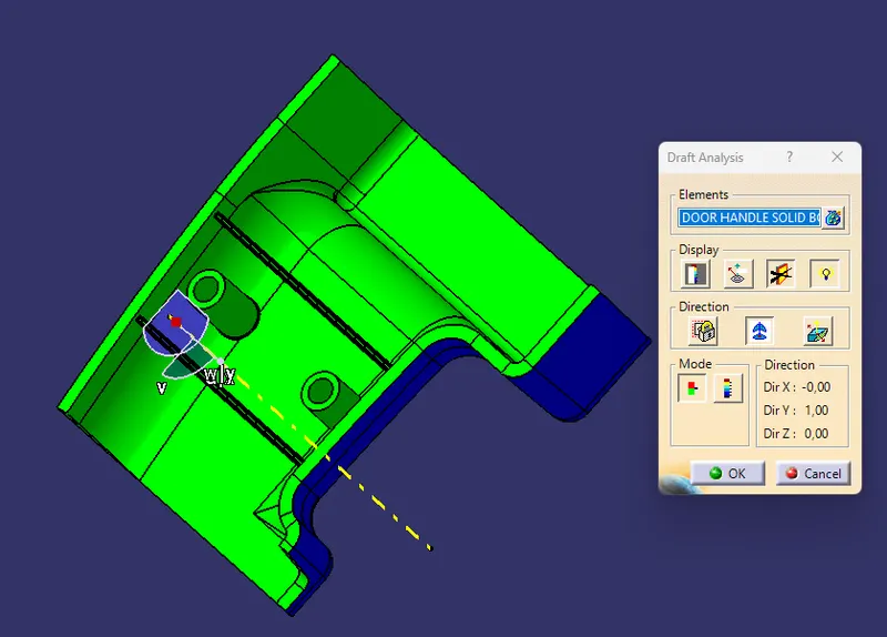
The Draft Analysis command determines if your draft portion can be readily deleted. This analysis method is based on colour ranges that define zones on the investigated element where the deviation from the draft direction corresponds to specified values at any location.
- Go to customised view parameter >under mesh >check the material and click OK before proceeding to the draft analysis.
- Go to insert » analysis » feature draft analysis now for draft analyses.
- To specify the draft direction, use the compass.
- Change the draft angle on the colour scale to 3 degrees.
- The component becomes green to indicate the passing draft angle.
- Check the angle of the component using a running point.
- The draft analysis is finished.
3. Creating Class B surface
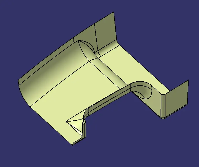
- Offset the class A surface with 3mm.
- Fill the patch with the help fill and sweep command.
4. Creating Class C surface
- With the boundary command, extract the boundary from the class A surface.
- As the border comprises domains, split it with a disassemble tool.
- Utilize sweep > profile type line > subtype as with draft direction > guide curve and draught direction > draught angle of 3 degrees > preview.
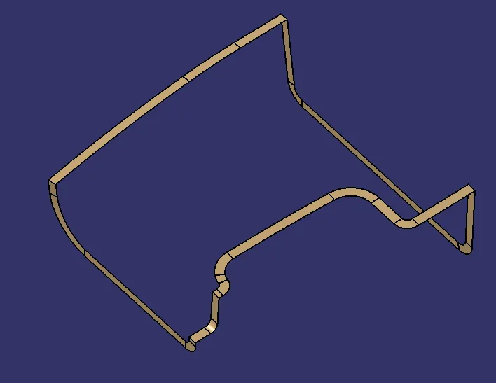
5. Surface and solid body
- After getting the CLASS-C Surface then add with the CLASS-A Surface and then trim the output with the Class B surface to get the final output.
- Now open the part design workbench and use a close body surface to create a solid component.
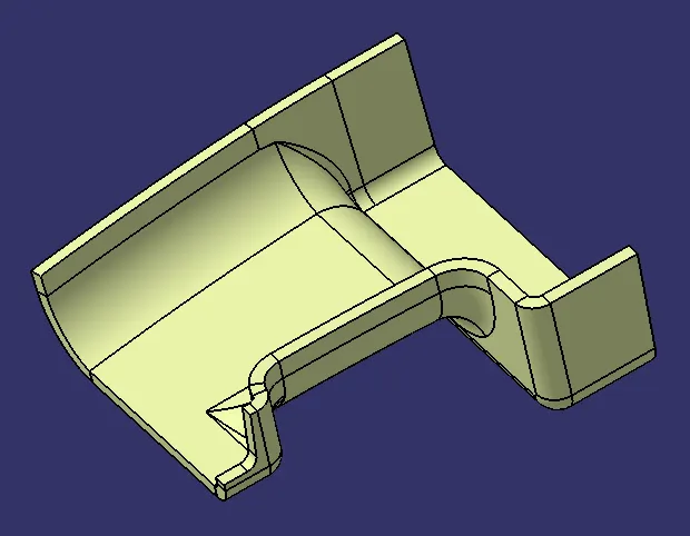
6. Creation of Engineering features
Rib
A rib is a cost-effective approach to enhance the stiffness and strength of mould sections without increasing the overall thickness of the wall. It is a narrow protrusion that is perpendicular to the wall.
- Create the sketch of the Rib.
- Apply the extrude command to the sketch.
- Then apply the trim command and add to the solid body.
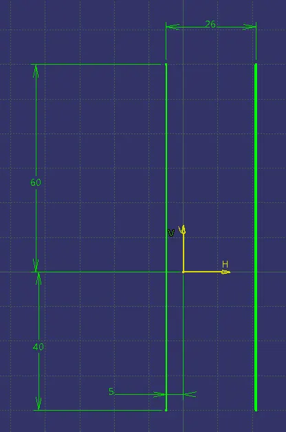
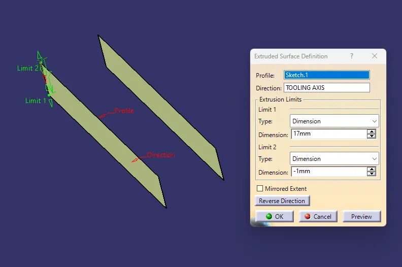
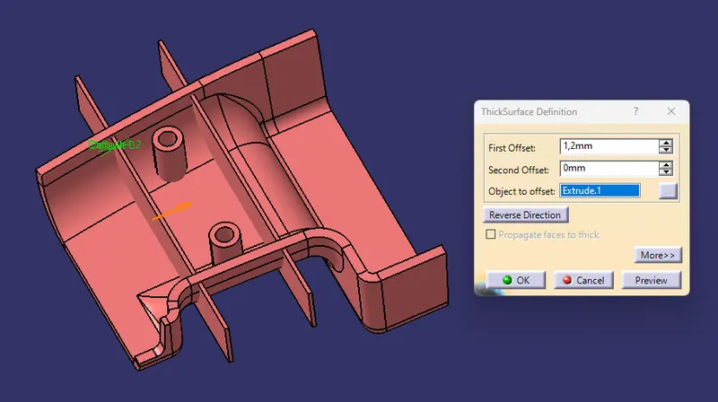
Rules followed during the creation of the Rib
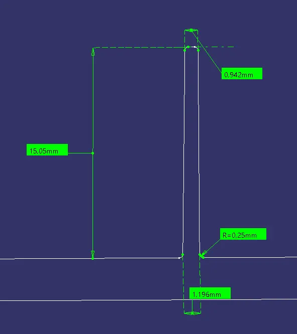
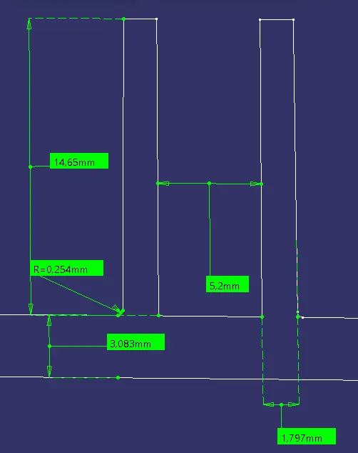
- Thickness W=0.4*T, as the t=3mm, then w=0.4*3=1.2mm as you can see in the below fig.
- Minimum thickness at Rib Tip greater or equal to 0.75mm. In the fig, you can see the Rib Tip is 0.942mm which is greater the 0.75.
- Rib fillet radius 0.25mm.
- Rib Height < 5*nominal wall thickness, 5*3=15mm.
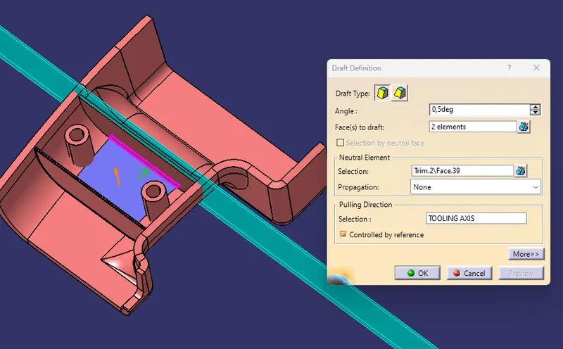
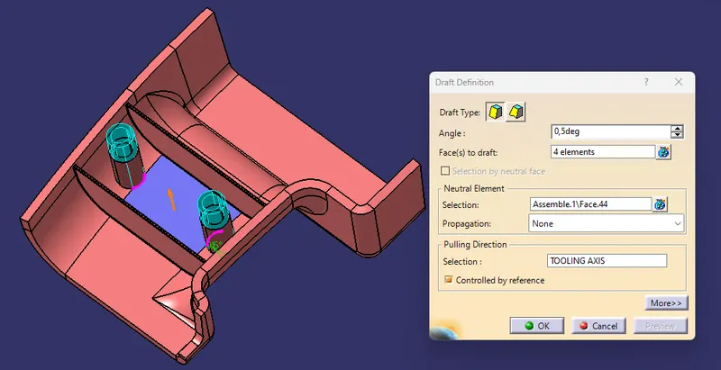
- A draft angle of 0.5 degrees per side minimum.
Root Thickness Analysis
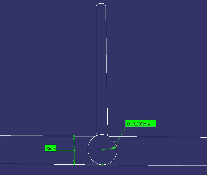
To determine the thickness of the Rib root thickness, first, draw a perpendicular intersection across the body and the Rib, and then draw a circle that is tangent to the Rib base or root region using a tri-tangent type circle. The value must be at least 30% larger than the thickness of the wall.
Wall Thickness * 1.3= 3*1.3= 3.95. As you can see in the fig the root thickness is less than 3.95mm. Hence, we can conclude that the rib is designed the as per rules.
Screw Boss
Screw bosses are used as attachment and assembly points, and are typically designed as a cylindrical projection with a hole to accommodate screws or other forms of fastening hardware.
- Create the sketch of the Screw Boss.
- Apply the Pad command to the sketch.
- Then apply the add command in between screw boss to the solid body.
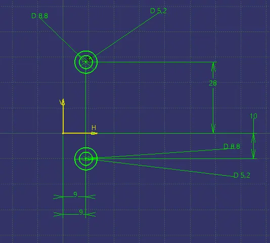
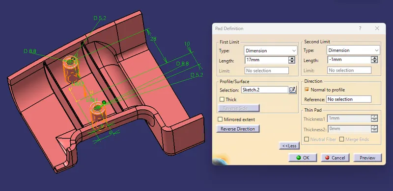
Rules followed during the creation of the Screw Boss
- Thickness W=0.6*T, as the T=3mm, then W=0.6*3=1.8mm as you can see in the below fig.
- The standard diameter of the screw is 5.2mm.
- Height should follow the ratio of 3H:1T (15:3).
- Rib fillet radius = 0.25mm.
- Maximum Draft angle= 0.5 degrees both inside and outside the wall of bosses.
FINAL PRODUCT
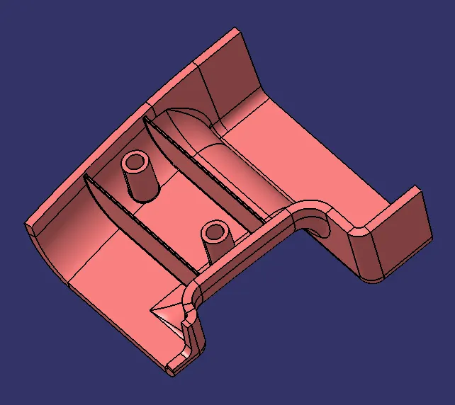
7. DRAFT ANALYSIS OF THE FINAL PRODUCT
Draft analysis is required to check whether a part has required a draft. The same procedure as the CLASS A SURFACE draft analysis but we have done it here for the solid component.
Screenshots of the completed design in various orientations (Isometric, Front, Side, and Top View)
Front View
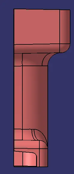
Right Hand Side View
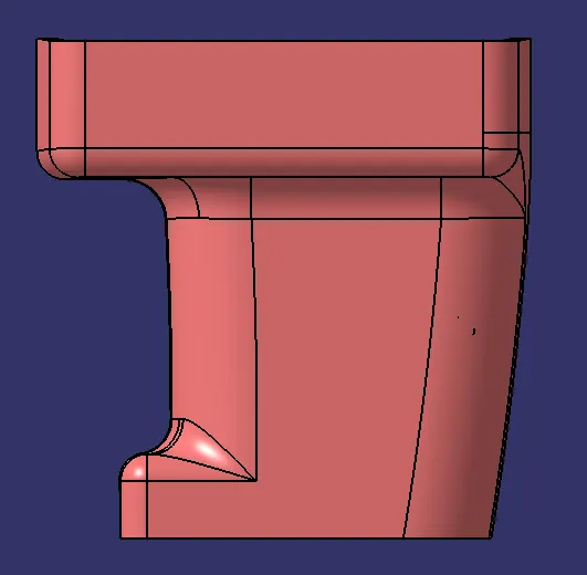
Left Hand Side View
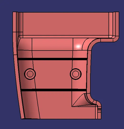
Top View
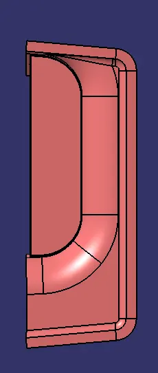
Isometric View