Challenge

Week 12- Final project

 AIM: To create a door interior part from the inputs of class A surface along with master section by following the design rules followed in tier 1               and OEM industries in catia v5

SOFTWARE USED: CATIA V5

OBJECTIVES

  • Create a sketch by using Positioned sketch
  • All the should be sketches should be Iso-Constrained
  • Ensured Proper Tree Structure
  • Geometrical sets should having a proper name based on the sketches present inside of it
  • Create thickened part using master section for reference
  • Create the mounting features as per design guidelines in the industry and with master sections
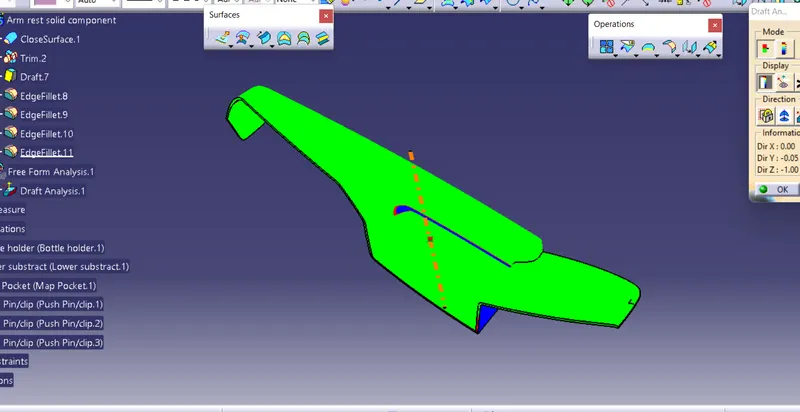
  • Creating of Draft analysis & Tooling analysis 

Lower substrate :

  • creation of tooling axis for the all components are desgined in the industry must and should perfrom the draft analysis for easy clearence from the core and cavity 
  • check visbility of clearance of all the areas for the given class A ensure that creating of tooling axis in that way 
  • for the lower substrate the below shown pic will clear maxium areas ,so i have in that direction
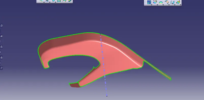
                      

                                                       Tooling axis for lower substrate

  • as we know the above fig will clear max area , so create A line normal to surface ,so it is our toolig axis
  • consider this line as tooling axis perform drafting on the class A 
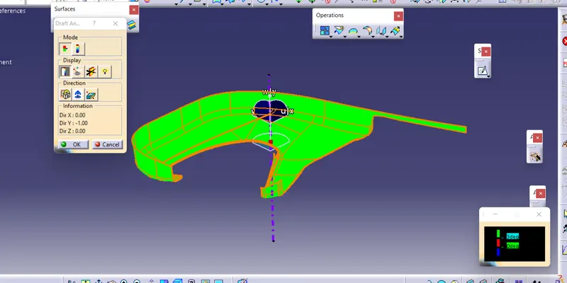
                        

 Creation of B surface : 

  • first offset the Class A surface for 2.5mm As given in the Master section
  • if there is any patches fill the patches and all should be closed
  • extrapolite the offseted area for making intersection between Class C for the further stepsF
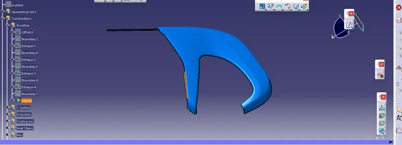
                             

                                                         B surface

Creation of C surface : 

  • For creating the Class C we need Extracting the boundary of Class A surface and it is make into smooth curves to sweep the curves by using support surface to the 90 degree respectively
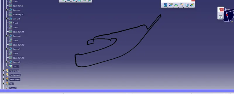
                                         

                                                                                     Class C 

   Final Trims to make a Closed Surface :

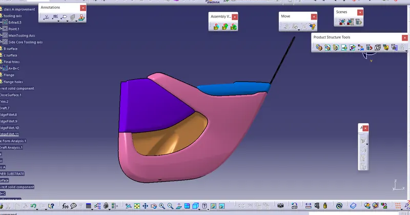
  • First trim Class B with class C and then Join with the Class A to make the closed surface
  • By applying the closed surface we will from a closed body
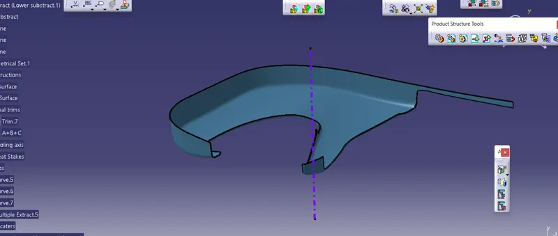
                

                                       A+B+C                                                                 draft analysis of A+B+C
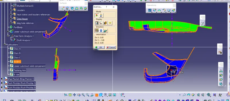


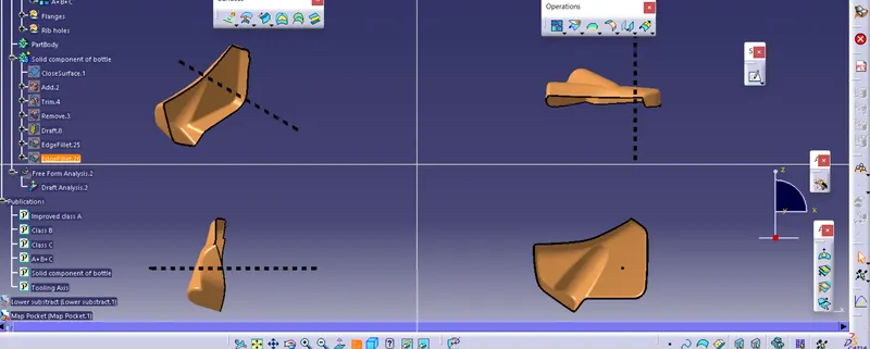
                                                                                    Top ,side,front views
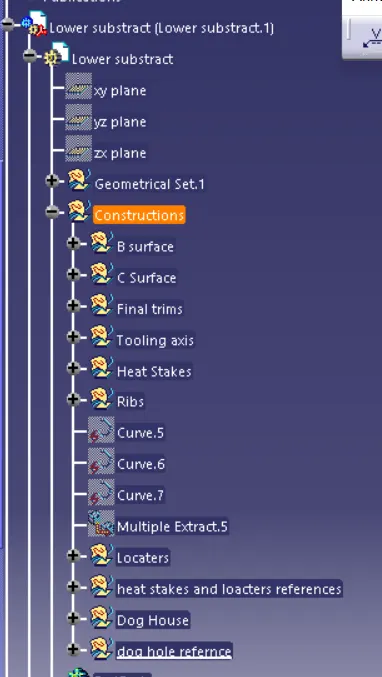
                

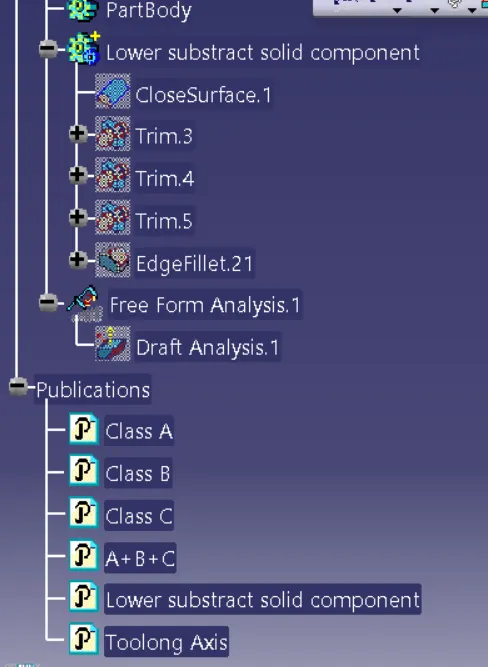
                                                                             Tree structure of Lower substrate

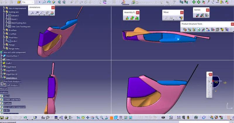
ARM REST : 

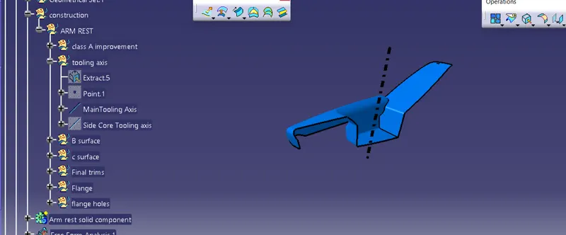
  •  First extract the base and create the point at centre,take the line with normal to surface and it is our main tooling axis 
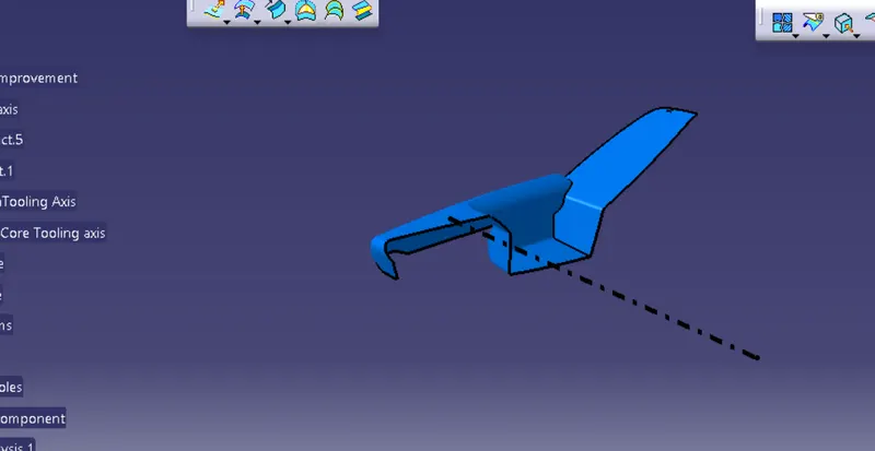
  • for the arm rest component will not clear with one tooling axis , so that we should create B side tooling axis for making clearance  between caore and cavity
  •                         

                                                                                       Main tooling axis 


                                                                                 Side core Tooling axis

Creation of B surface :

  • For creating B surface for Arm rest is somewhat difficult , for that first we want to offset the for Class A surface and it will provide Patches while offsetting 
  • Fill the patches by Multiple extract and should make the single Class B surface
  • extrapolit the B surface for making the intersection between the class C surface in the further steps
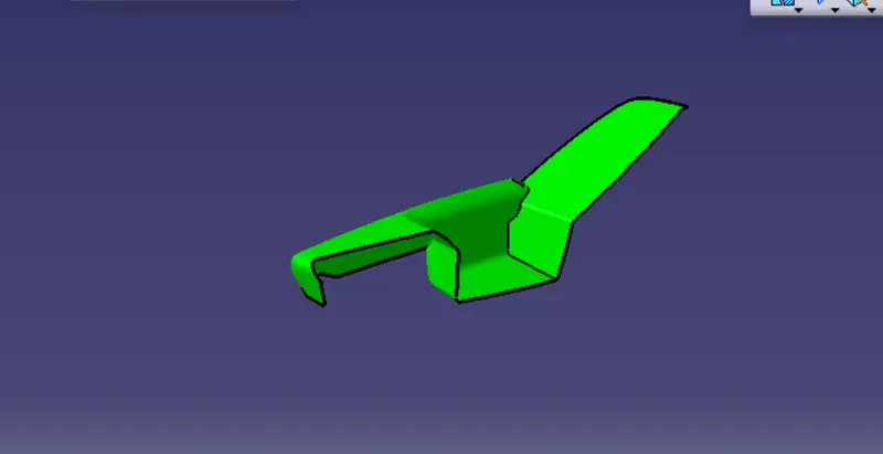
                                        

                                                                             Class B surface

Creation of the C surface :

  • for creating C surface we want use the Sweep command with 93 deg in respective  direction 
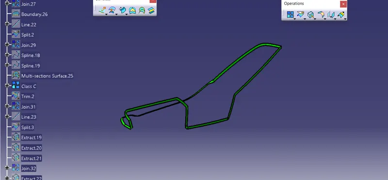
                                         

                                                                                 C surface
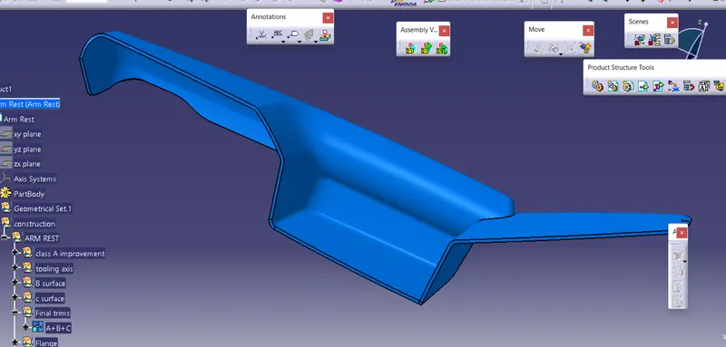
                                  

                                                                                             A+B+C
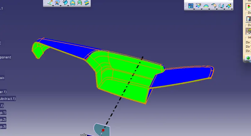
 

                          Side core tooling axis                                                                             Main tooling Axis
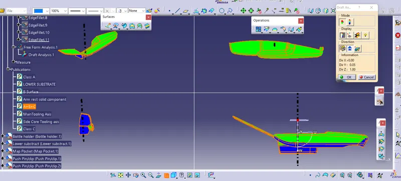
                

                                                                      TOP,SIDE,BOTTOM Views
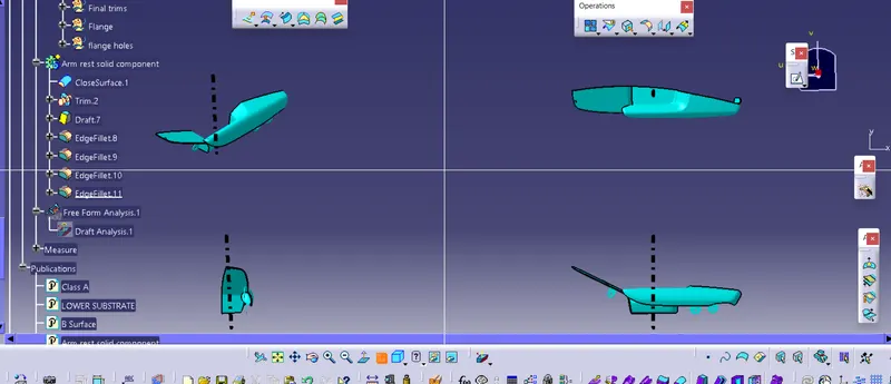
                  

                                                                                 Solid component
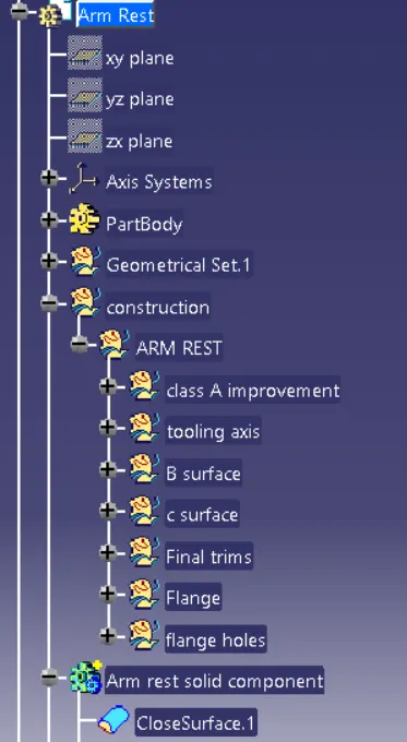
                   

                                                                   Tree Structure of arm rest

Creation of Map pocket:  

  • Check the comdition of Class A then offsetting with 2.5mm and do the filling of patch work with multisection and do extrapolation for intersection between Class B and Class C in further
  • then create the tooling axis with normal to surface and perfrom the Draft analysis and check whether it clear or not
  • then create the C surface by sweep command with 93 deg 
  • trim class b with class c and join with class A for closed component
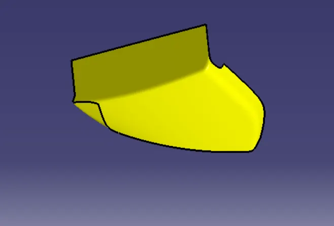
                              

                                                                                        Class A 
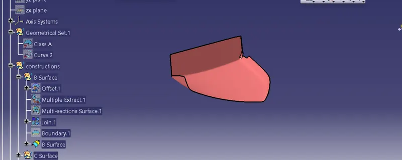
                  

                                                                             Class B
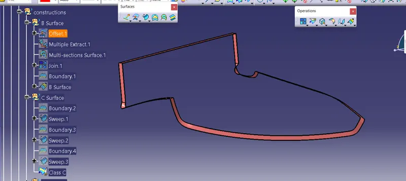
                

                                                                                      Class C
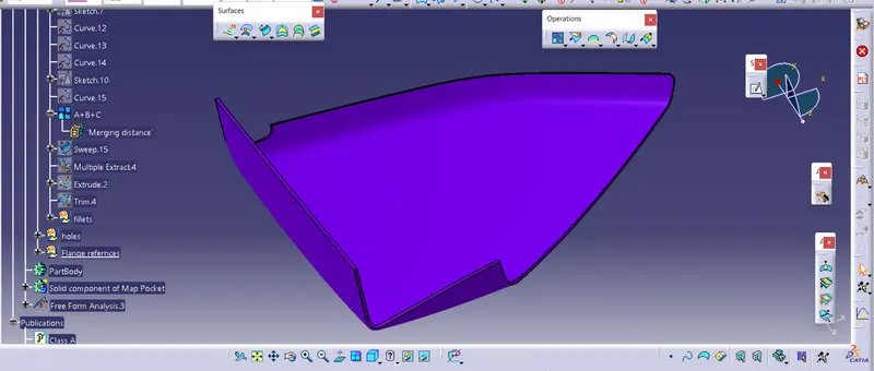
                   

                                                                                     A+B+C 
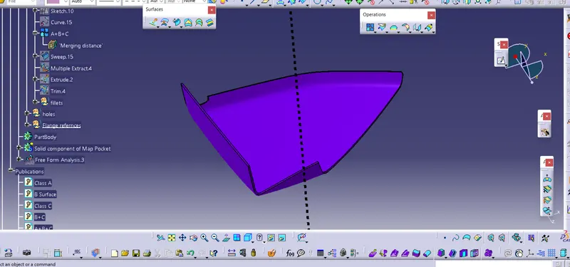
                 

                                                                           Tooling Axis
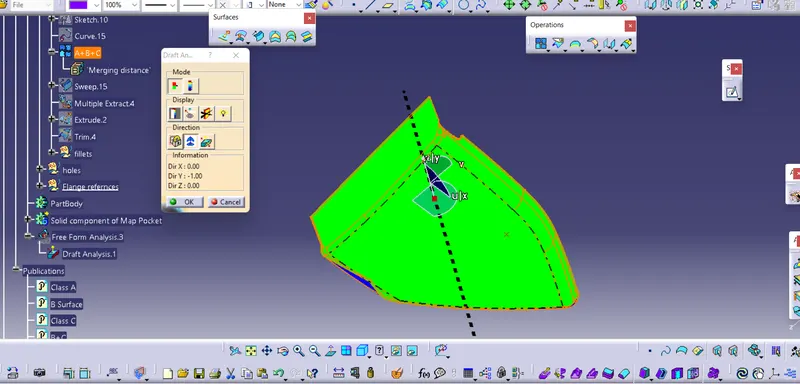
                         

                                                                                    Draft Analysis
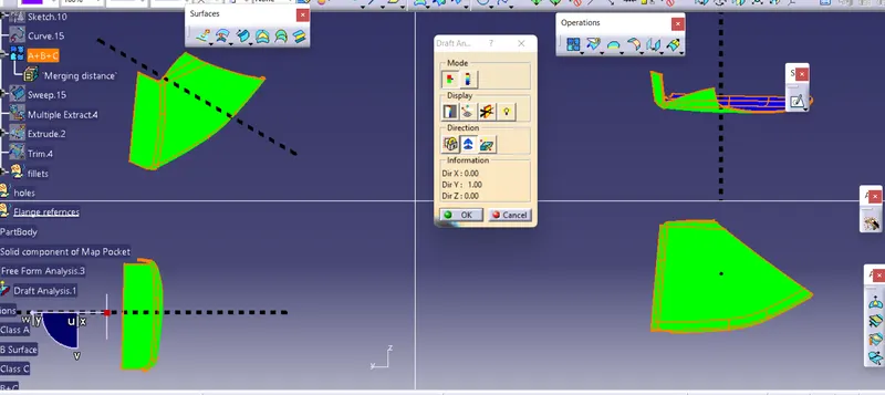
                   

                                                                               Top ,fornt,side view
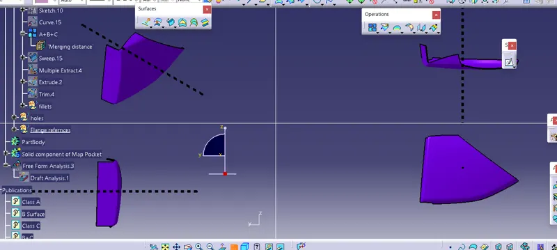


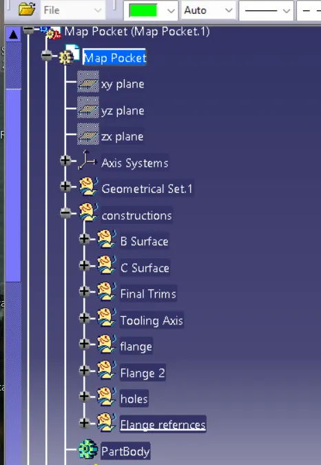
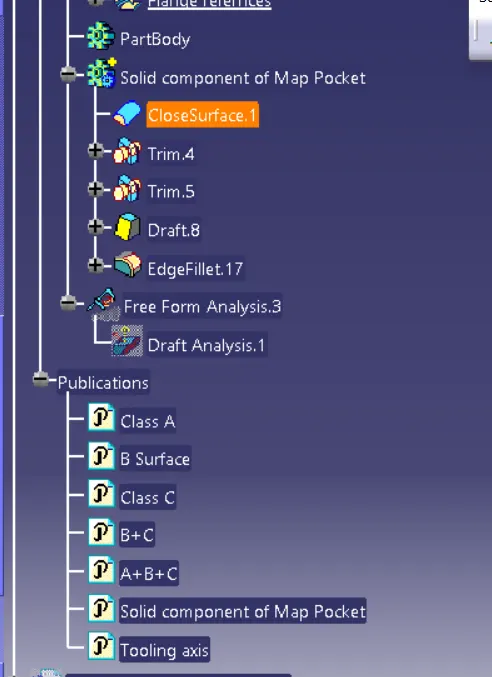
                                                                      Tree Structure of Map Pocket 

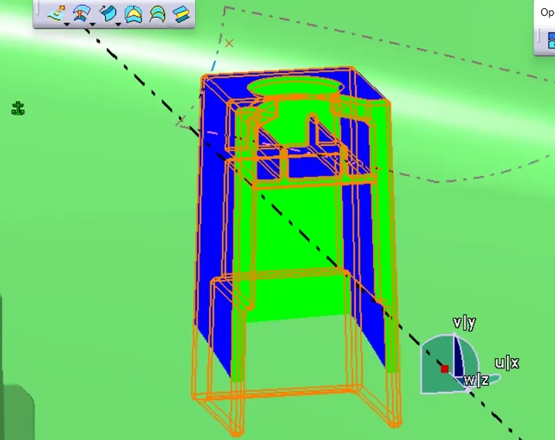
Bottle Holder :

  • Check the comdition of Class A then offsetting with 2.5mm and do the filling of patch work with multisection and do extrapolation for intersection between Class B and Class C in further
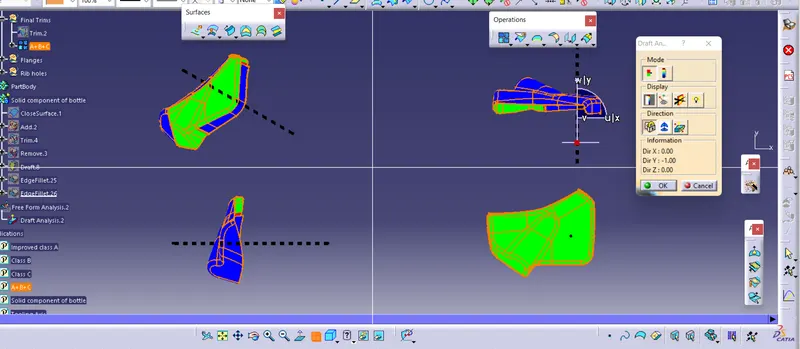
  • then create the tooling axis with normal to surface and perfrom the Draft analysis and check whether it clear or not
  • then create the C surface by sweep command with 93 deg 
  • trim class b with class c and join with class A for closed component
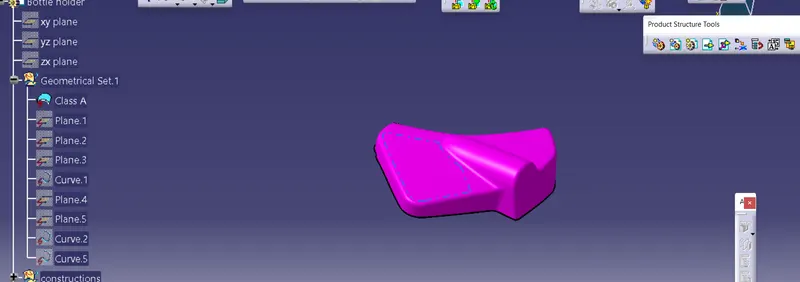
                 

                                                                                       Class A
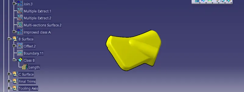
                 

                                                                                 Class B
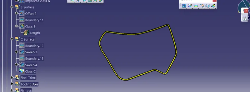
                

                                                                                          Class C
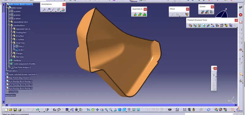
              

                                                                                         A+B+C
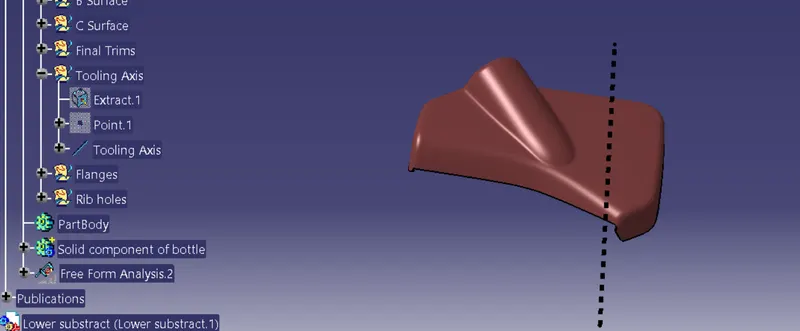
                

                                                                                   Tooling axis

             

                                                                            Draft analysis


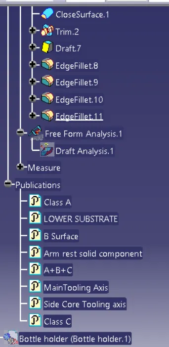
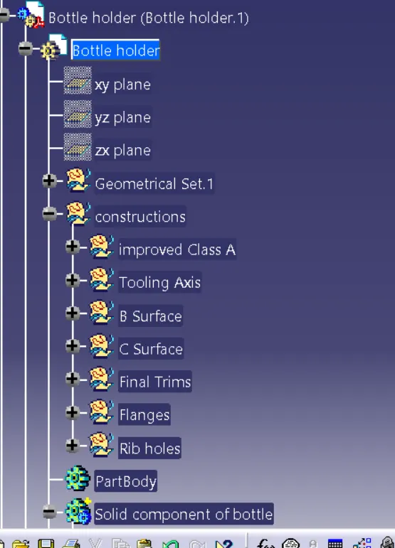
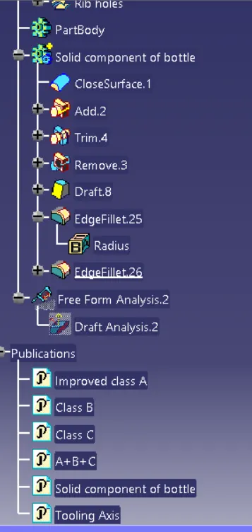
                                                                  Tree Structure of Bootle holder

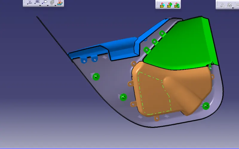
Attachment features :
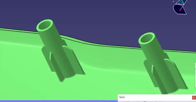
                  

                                                                                Heat Stakes
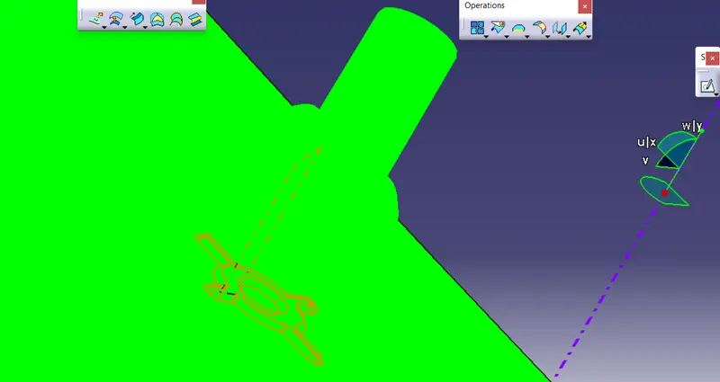
                    

                                                                            Draft analysis of heat stakes
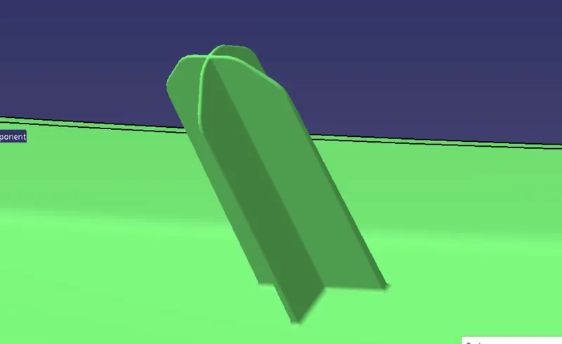
                      

                                                                             Locaters
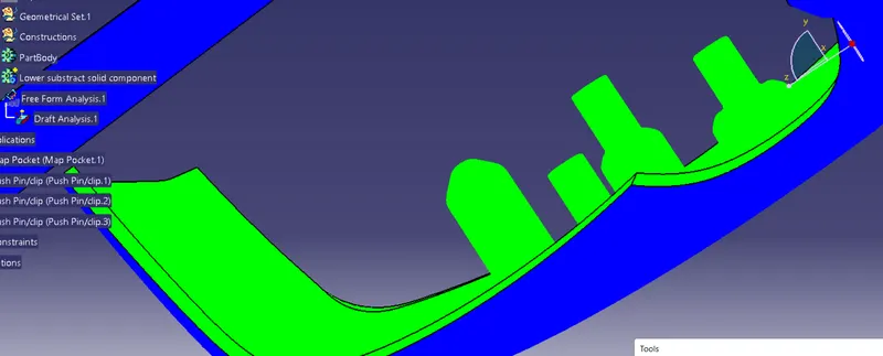
                

                                                                  Draft analysis of heat stakes and locaters
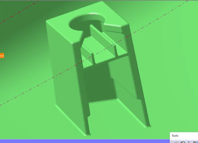
                

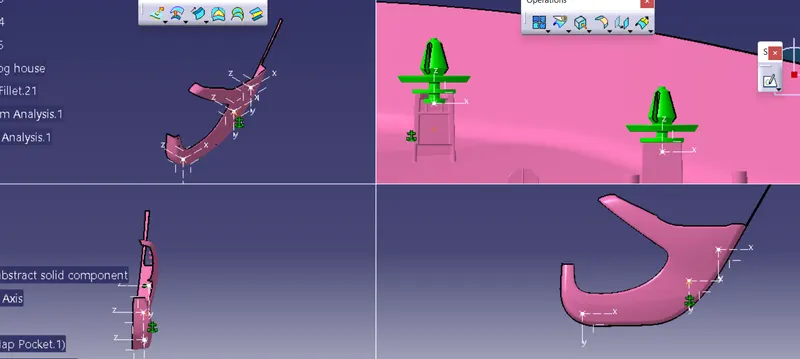
                                                                                     Dog house  
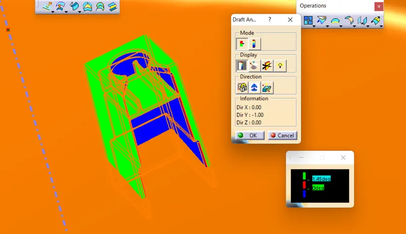
   

                     Draft analysis of dog house (Main tooling axis)                                                 Side tooling axis
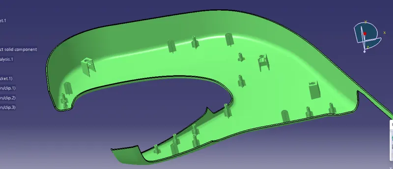
                   

                                                                 Heat stakes , Loacters and Dog House on Lower substrate
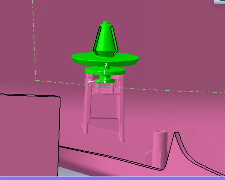
                   

                                                                 Push Pin fixed on Dog house
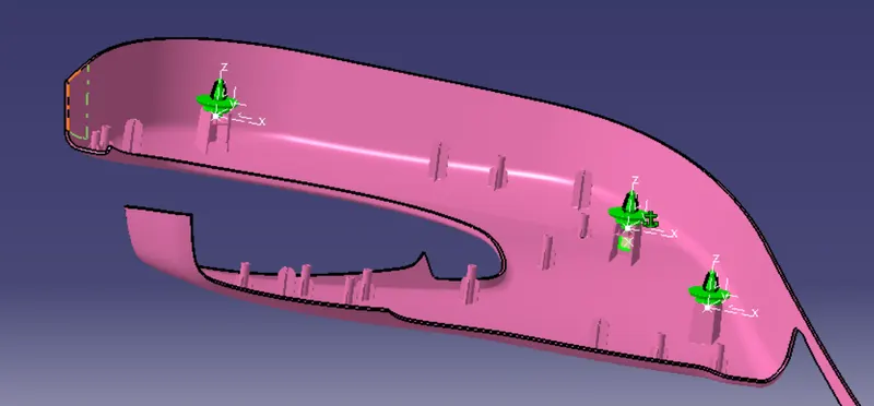
                

                                                      B side features on Lower substrate


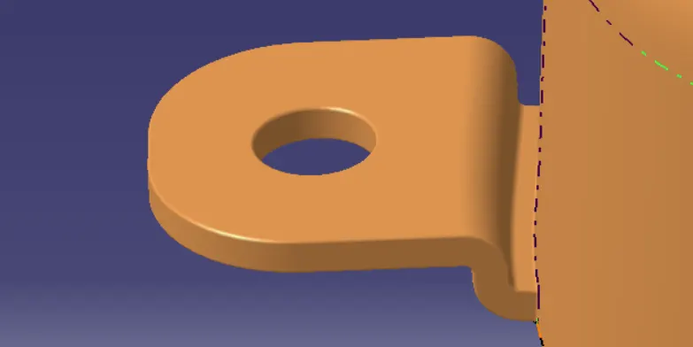
                                                                         Flange on Bottle Holder                                                                    
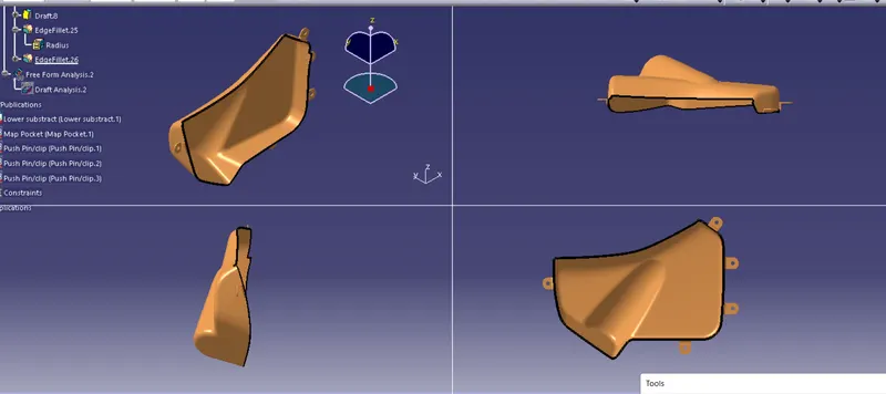
                   

                                                                                B side Features on Bottle Holder
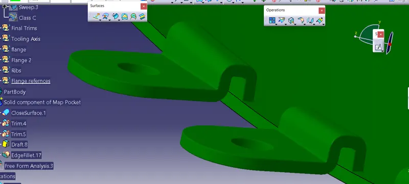
      

                                                                                          Flange on Map Pocket
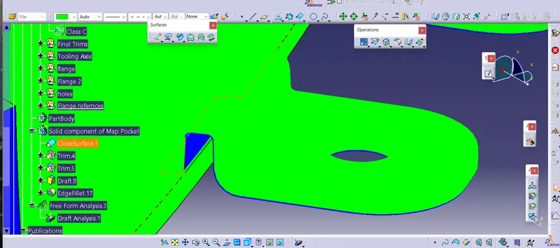
                     

                                                                                Draft Analysis on Flange
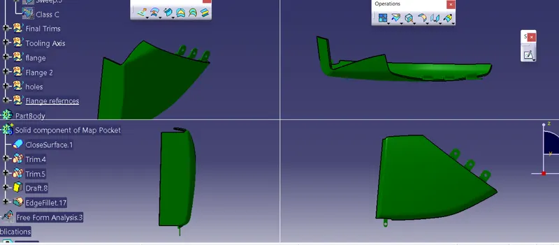


                                                                       Flanges on Arm Rest                                                           


                                                                   B side features on Arm Rest

Door Trim FInal Views:
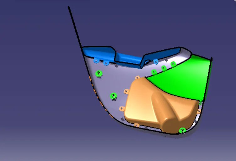


 Catia part and product file attached below for your reference

Your portfolio, next

Ship work like this
in your own course.

Talk to a career counsellor

Free 20-minute call. We'll map the right course to where you want to work.

By submitting you agree to our Terms and Privacy Policy.