Week 12- Final project
Development of a Door Trim panel
OBJECTIVE:
- Creation of CAD model considering the following inputs as like in OEM and tier1 companies
- Class A surface
- Nominal thickness: Refer to master sections
- Attachment strategy :
- Find an attachment strategy for the door panel complete work.
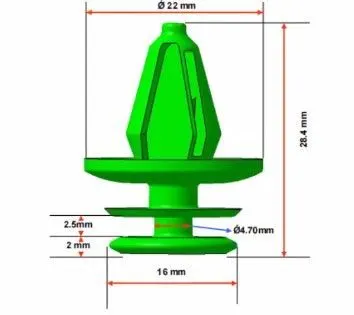
- Use Push pin with Dog house for Lower substrate – Door panel attachment
- Use heat stakes for part-to-part attachment
- Draft analysis & Tooling analysis
REPORT:
INTRODUCTION
PRODUCT LIFE CYCLE
- Concept sketch
- Styling class A
- Feasibility check
- Concept validation
- New Product Design
- Product Development Proto Build
- Design Validation
- Pilot Production
- Mass production
NEW PRODUCT DESIGN:-
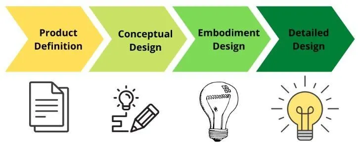
In this stage, the major work of product design is done, by taking inputs from the concept sketch to validate that the product will go to design using design software such as Nx, CATIA, Solidworks, solid edge, etc. In this stage through design, all the surfaces are divided into sub-parts from the class A surface and Ensure the product should be workable.
CREATION OF CAD MODEL
CAR DOOR TRIM
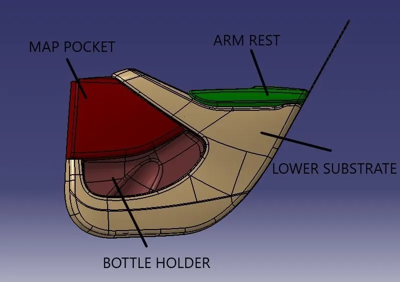
- MASTER SECTION DEVELOPMENT:
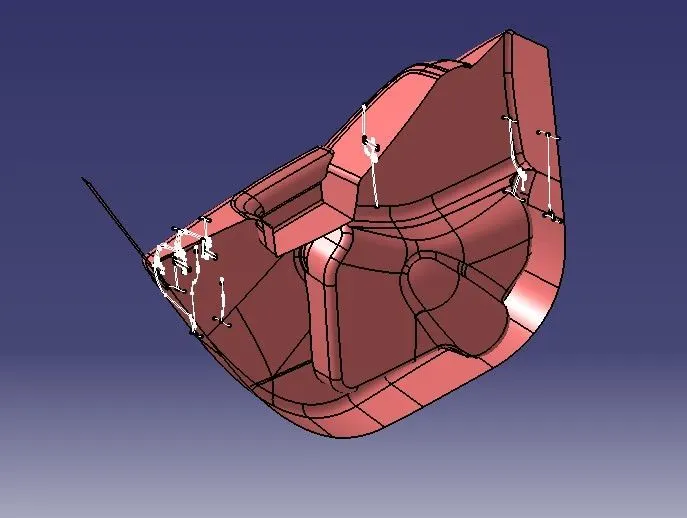
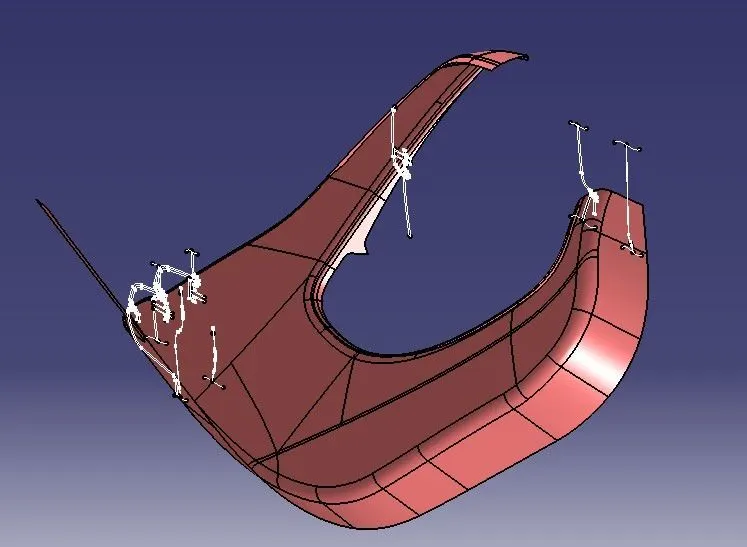
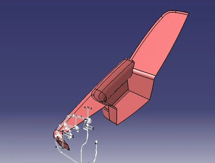
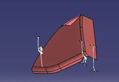
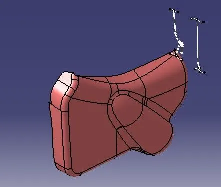
- Class A surface modification as per master section:
- From the given data we have to do a cad model for
- LOWER SUBSTRATE
- ARM REST
- MAP POCKET
- BOTTLE HOLDER
CLASS B SURFACE:-
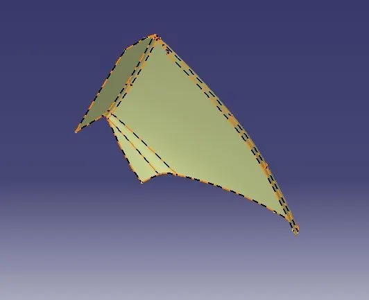
Class B surface is created by direct offset and creates a surface using multisection surface, extrapolate, etc
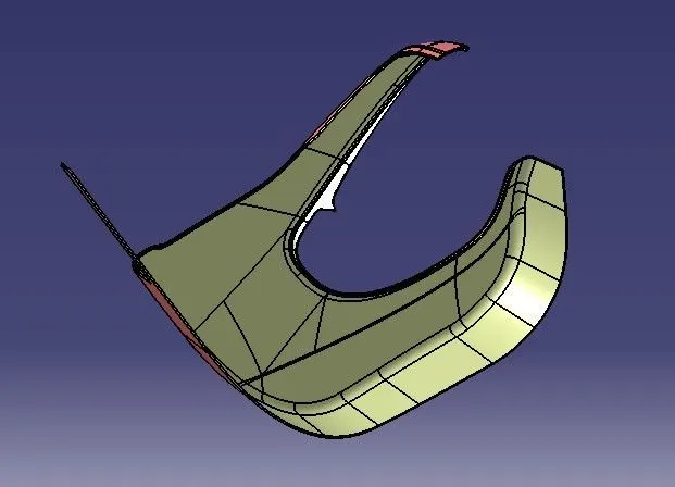
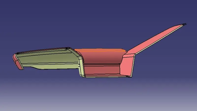
Class C surface:-
Class C surfaces are created based on the tooling direction as well surface reference.
Creating Swept Surfaces The swap tool is provided to create surfaces by sweeping a profile along a guide curve in the Wireframe and Surfaces Design workbench of CATIA V5. To create a swept surface, you first need to draw a profile and a guide curve as two separate sketches
Creating Swept surfaces with draft direction: similar to Creating Swept surfaces but we have to select a direction for the draft.
Creating Lofted Multi-Section Surface: This tool allows you to create lofted multisection surfaces. The surface is created between the sections along the computed or user-defined spine. To create a multi-section surface, you first need to create sections and guide curves. Next, choose the Multi Sections surface button from the Surface toolbar; the Multi-section
Final trimming:-
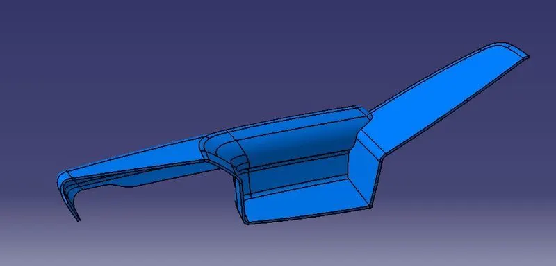
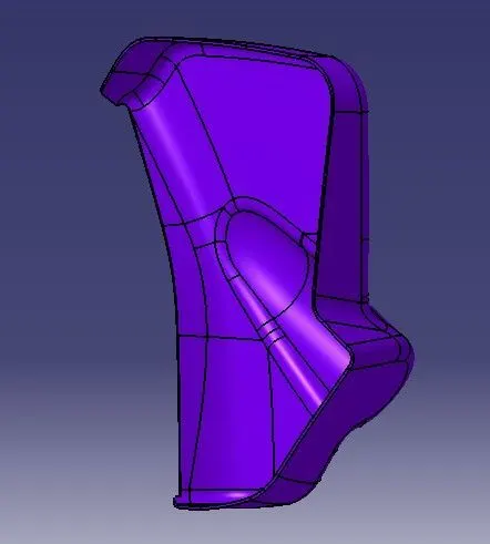
Class A, with Class C and Class A + C with Class B. using Trimming Surfaces Insert > Operations > Trim
The Trim tool allows you to trim two intersecting surfaces or curves with respect to each other. When you invoke this tool, the Trim Definition dialog box will be displayed, Choose a surface as the first element and the other surface as the second element. One side of each surface will be displayed as transparent. You can choose the Other side button to reverse the sides of surfaces to be trimmed.

DRAFT ANALYSIS:-
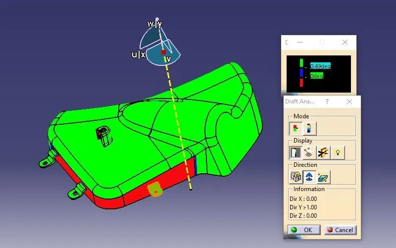
Draft analysis is performed based on color ranges identifying zones on the analyzed element where the deviation from the draft direction at any point, corresponds to specified values. The minimum draft angle is considered as 3 degrees.
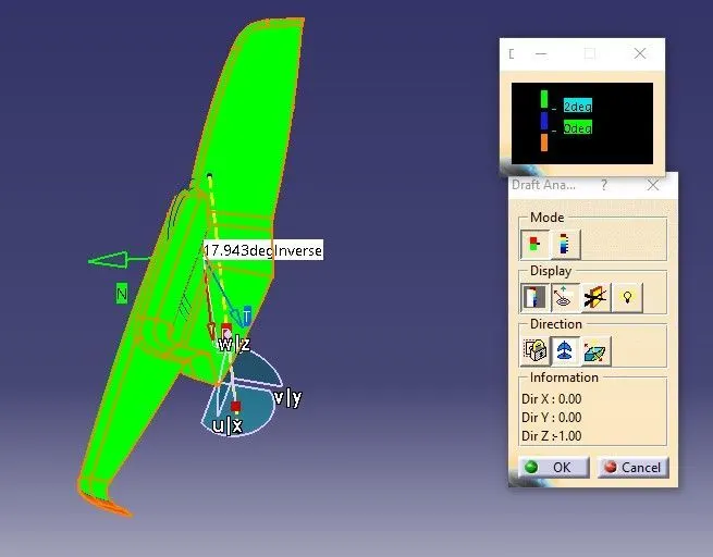
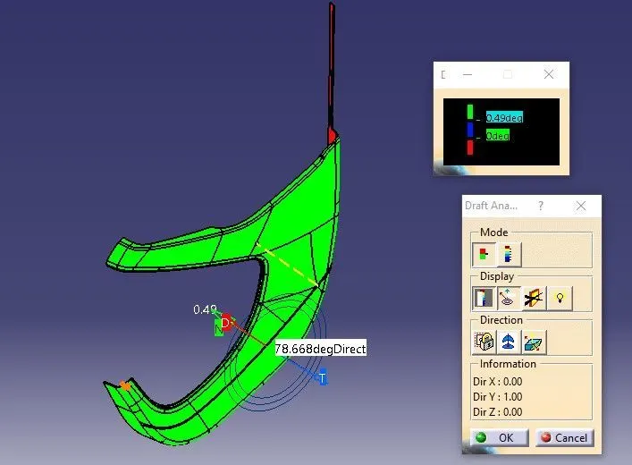
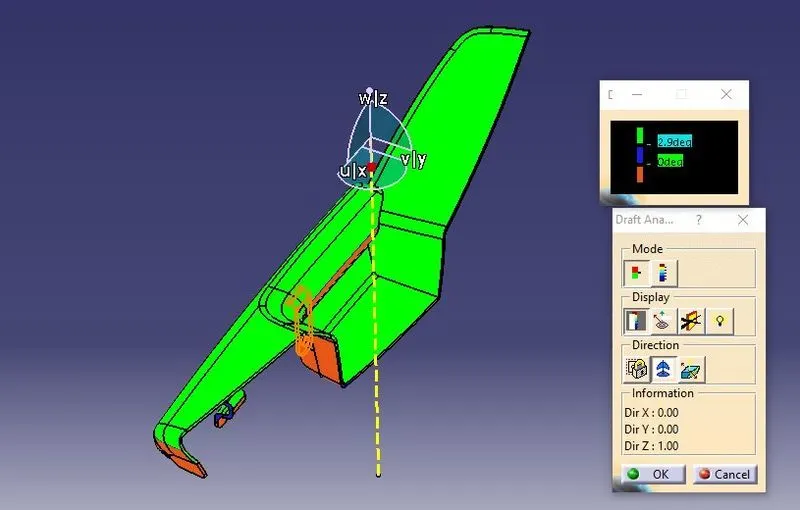
- Screenshots of the Draft analysis report for both the given Class-A surface and the final plastic component.
- CREATION OF ATTACHMENT;
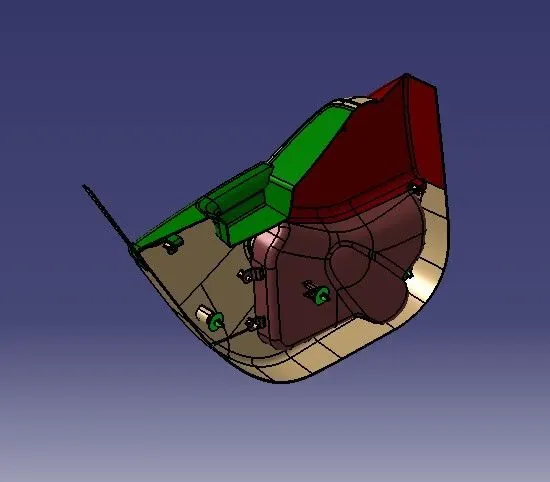
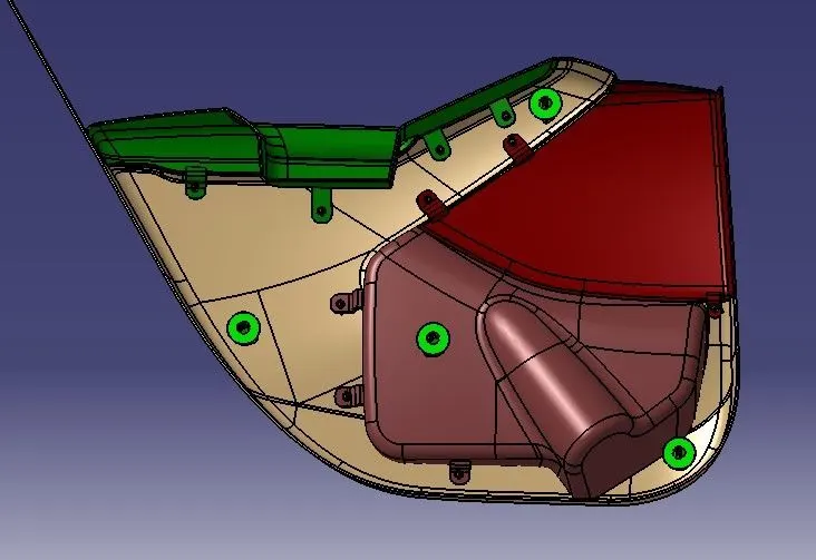
- The heat stakes are created for part-to-part attachment as per the master section, here some of the heat stakes are having ribs, because they have more than 1.6 of Dia, so in order to give strength we have ribs. all heat stakes are done on the Lower Substrate.
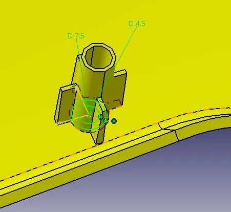
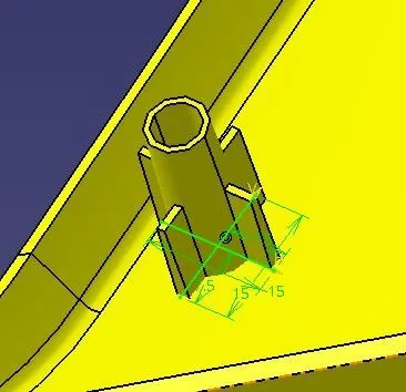
DOG HOUSE CREATION:-
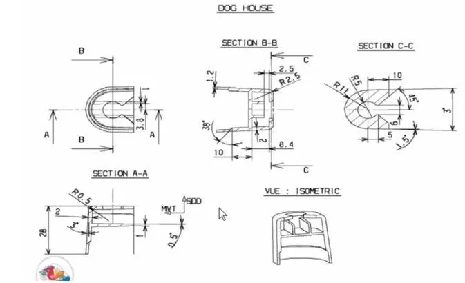
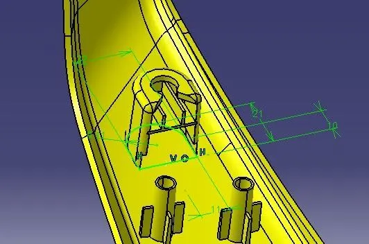
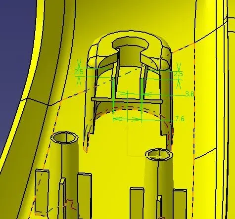
- Doghouses are created by following the design rules.
- For this, the sketch is created from the master section provided.
- It is then made into a closed body and is made into a part model.
- Shell operation is performed to get a hollow structure and then coring is done in order to avoid sink marks in the class A surface.
- Drafts are given for the surfaces as per design rules and proper fillets are also provided.
- As per the given master section, ribs, and supporting features are also added in the doghouse.
- Then, the doghouse is added to the main body.
FLANGES AND HOLE CREATION:-
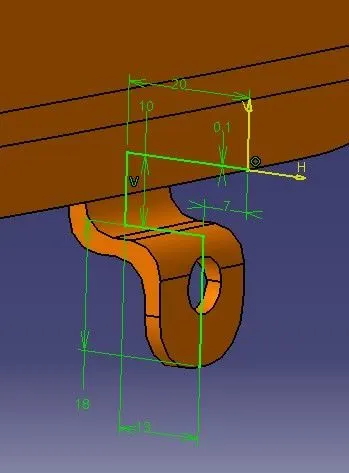
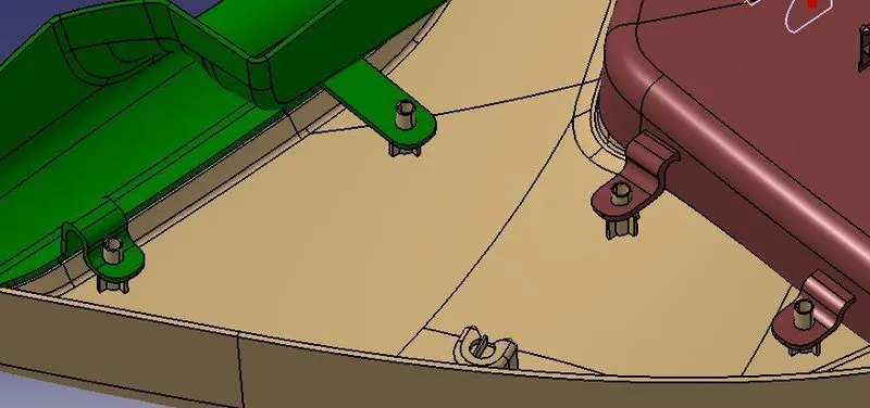
Create Doghouse and push pin for assembly of the panel with BIW part.
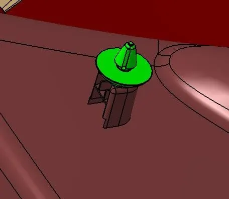
Draft analysis & Tooling analysis for the final product:-
In the injection molding process, plastic products are difficult to de-mold due to friction force between the cavity and products, thus, finished products might be deformed or damaged. Therefore, designers should add a draft angle to the geometric surface of products, which is parallel to the unloading direction, in order to help the products eject smoothly from the cavity. This study uses CAD software as the main architecture to develop the function of automatic draft angle recognition and construction. The study is divided into three stages. First, the geometric features of products are identified in the CAD model by an induced algorithm, then the quilts to be added to the draft design are determined and classified. Finally, draft angles are created in different ways according to different surfaces
The draft analysis button within CATIA V5 will help you quickly gather the draft angle on multiple surfaces without the need for tedious manual measurements. Here is a quick rundown of how the icon works when you have a given die direction.
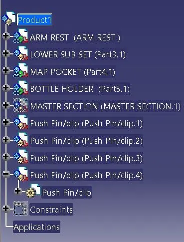
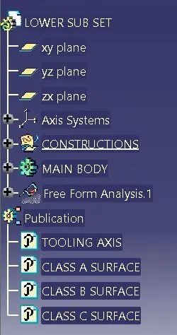
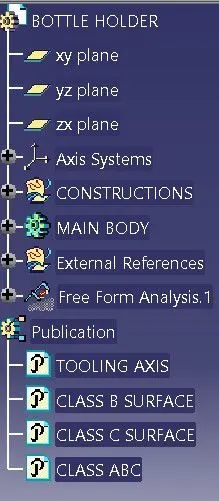
TREE STRUCTURE:-
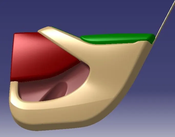
FINAL COMPONENT:-