Week 12- Final project
DESIGNING OF DOOR TRIM - PLASTIC DESIGN FINAL PROJECT
Aim:
To develop the door trim (interior) panel with the given class A input and master sections using CATIA V5.
Objective:
The main objective is to create the individual components of the door trim with given input class A surface and create the class B, class C surface and generate the solid surface body out of it and perform the proper draft analysis with required draft angle of 3° for the body and continue the procedure for the remaining components .Then start creating the B side Enigneering features of the components by following the reference of the master sections provided and perform the draft analysis with an input draft angle of 0.5° and assemble the components to for the final door trim panel on the assembly workbench by providing necessary constraints using catia V 5 software.
- To create the tooling Axis and Performing draft analysis on the Class A.
- Class B surface creation
- Class C surface creation
- Use the Close Surface feature to make a solid body from the surface.
- Draft analysis of the solid body
- creating the B side Engineering features by considering the design rules.
- Draft analysis of the solid body along with the B side features.
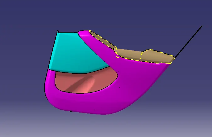
- Create the parting line
Door Trim Components:
- Arm Rest
- Lower Substrate
- Map Pocket
- Bottle Holder
- Push Pin
B-Side Engineering Features:
- Dog-House
- Heat Stakes
- Ribs
- Locators
1. Arm Rest:
Arm rest is the supporting element in the front of the car, a central armrest, which commonly folds away based on user preference, will also often include a storage compartment and sometimes even cup holders. Some also provide the location for controls for non-essential functions of the vehicle, such as climate control or window motors.
Class A:
Class A surface is the aesthetic skin data for the automotive part designing and curvature surface to represent the main component.Befor proceed with A surface to analys the Draft angle, if get any mis-match surface reconstruct the A surface.
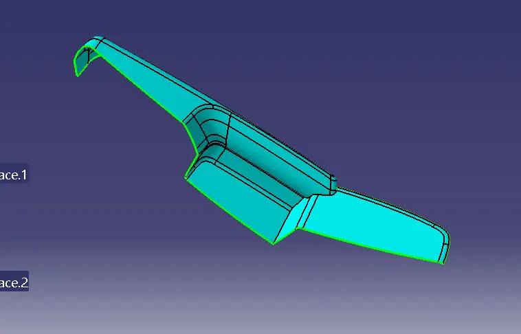
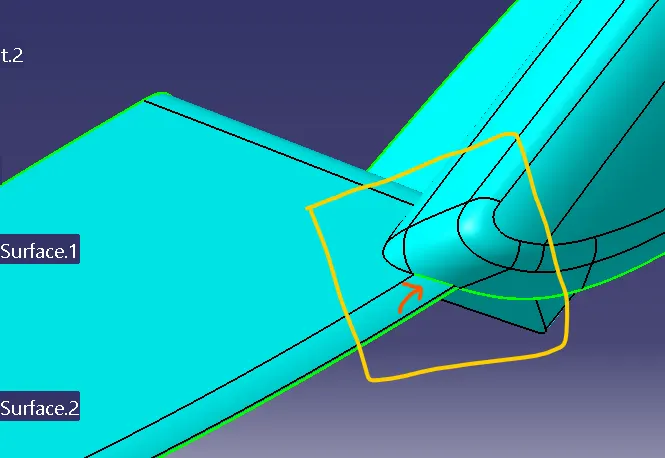
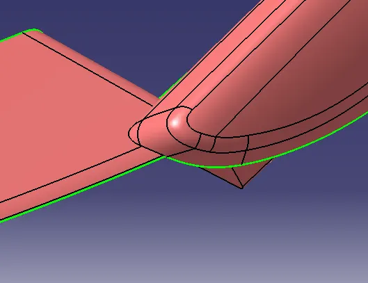
The given class A surface has a small patch in one area,so reconstruct the class A surface.
Tooling Axis:
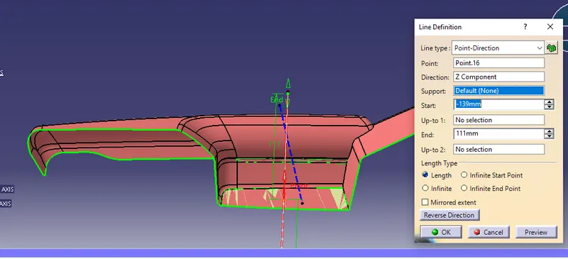
In plastic design injection molding the Tooling Axis is the most important criteria. The tooling axis along to the core and cavity area, also the component ejecting ways of the core and cavity is most common in tooling direction only. For creating the tooling axis in this drill handle is differnt and very ease with comparing to the previous plastic component design.
Here first extract the flat surface and created the point the option of point on surface to the extracted surface and select the zero point.
Class A Draft Analysis:
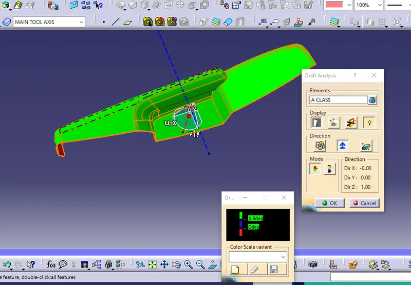
Draft is the main requirments in plastics molding. If the draft angle is less than 0 degree, the part or component and tool is to be damaged in mass production. If the draft angle is less than 0 degree, the part or component and tool is to be damaged in mass production. Also the molding part would not eject from the core and cavity. So avoid the damage and lack of productin the drafting analysis to find out the lesser angle are by the colour variation.
Class B:
For create the class B surface here we directly offset the class A surface to the total thickness of close body to inward direction some of the surfaces give offset error and ask for offset without these subelements click okay and work on the incomplete surfaces by using the multi-section surface command or extrapolate, fillet and different commands used to complete the class B surface.
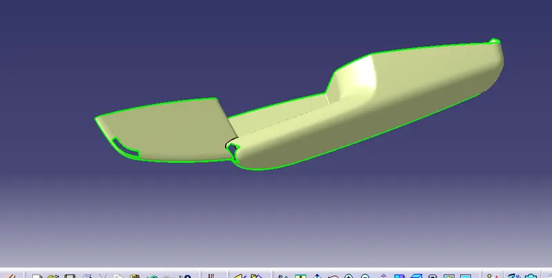
Thickness of the component to be 2.5 mm
So offset the class A to 2.5 mm inward, inthis case fillets are showing some error. Because of the inward offset the fillet will be reduce.At this moment we reconstruct the B surface with respect to the A surface.So using multi section surface command and create the surface which is in the missing fillet area. Then spilt from the offset.1 and using join with the option of sub element to remove to the remove fillets and extracted surface from the offset1.
Class C:
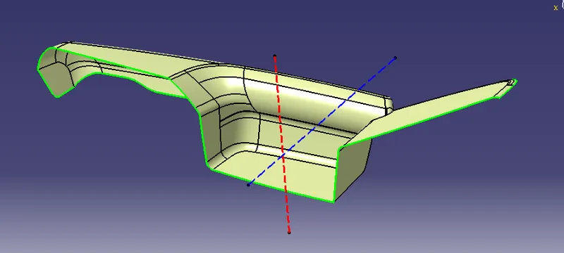
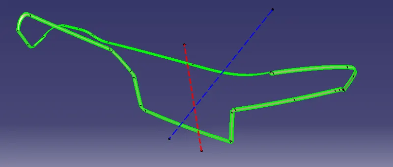
We first createste boundary from the Class A surface edges with the help of the multi extract or boundary command which we create the curve for sweep command. For creating the C surface draw a boundary to the class surface edges and sweep the edges with draft direction and with reference surface. The surface which is paralel to the tooling axis to use the sweep at the draft direction and the surface which is perpendicular to the tooling axis is swept with the reference surface.
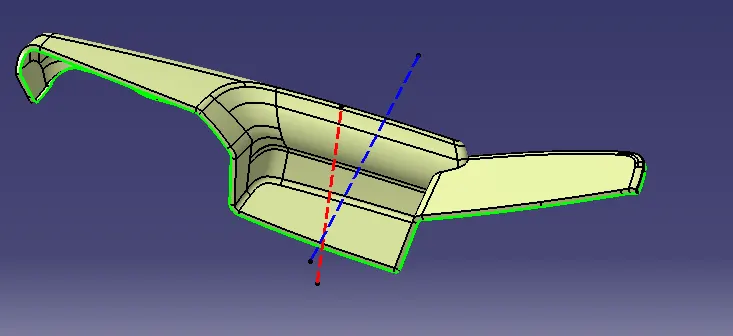
Class A & C:
To join the class A and Class C surface by using join command.
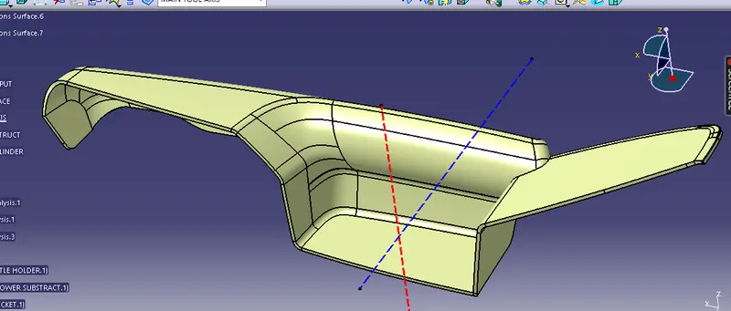
Final Trim:
To trim the Surface (A+C ) with the B surface.
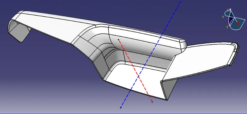
Close Solid Surface:
START -> MECHANICAL DESIGN -> PART DESIGN -> SURFACE FEATURE -> CLOSE SURFACE
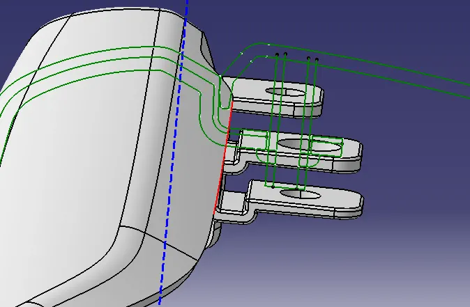
Create Flanges Through Master Section:
- In case of te door arm rest we need to folow the master section provided for the flange creation
- The thickness of the flange is equal to the thickness of the plastic component that is 2.5 mm
- To use the master section as reference and create the sketch and generate the surface, then make ticken surface.
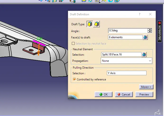
- The draft provided is 0.5 deg
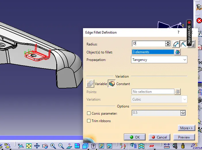
- Apply requierd fillets on all the sharp edges
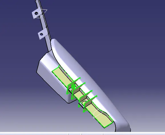
Draft the flanges at the angle of 0.5 degree and make the edhe fillets
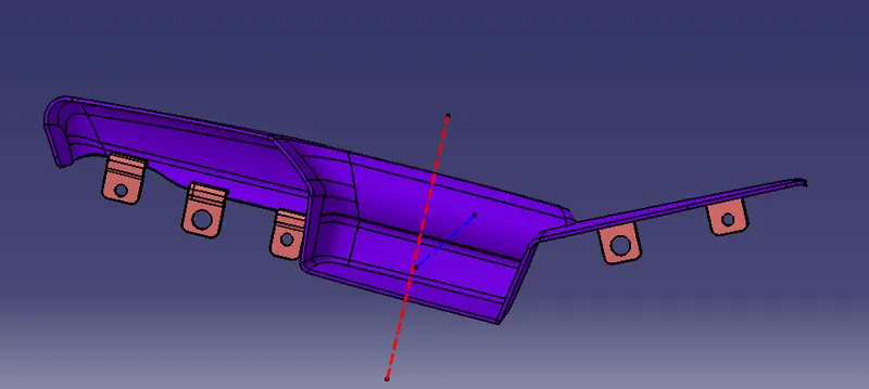
Draft Analysis Close Solid Body:
Final Close Body Draft Analysis:
Procedure for performing the draft analysis are as follows
- Change the view mode of the component into customized parameter mode and then select the shading option as material mode.
- Then open the featured draft analysis tool from the insert menu -> Analysis.
- Then click the compass and drag the axis to define the current drafting direction to tooling axis.
- Then lock the draft direction and perform draft analysis by pick the component.
- The green colour shows the positive daft tooling direction and the given surface passes the draft analysis.
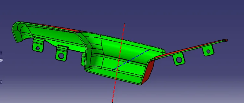
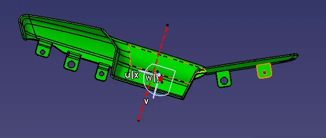
Sdie Core axis
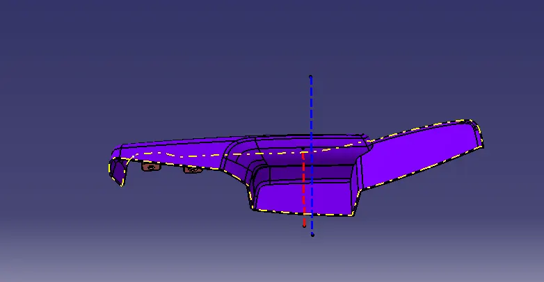
Parting Line:
2.Map Pocket
Map pocket is the sub element situated right at the hub of the lower substract of the door trim panel . The processs illustrated is same as the prevous components first, we need to check the boundary of the given input surface whether there might have any open patches or else protrude the input surface as the required class A surface
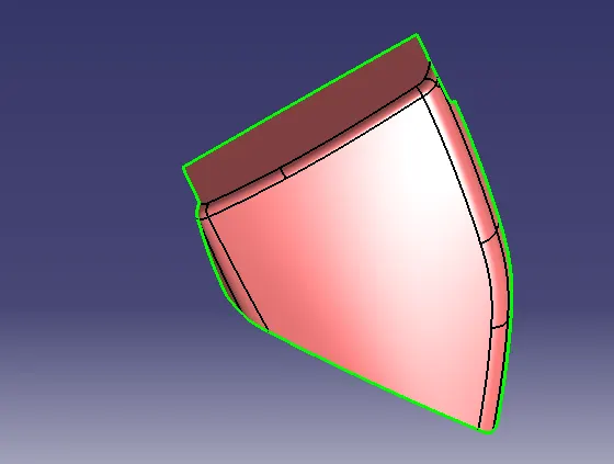
Tooling axis:
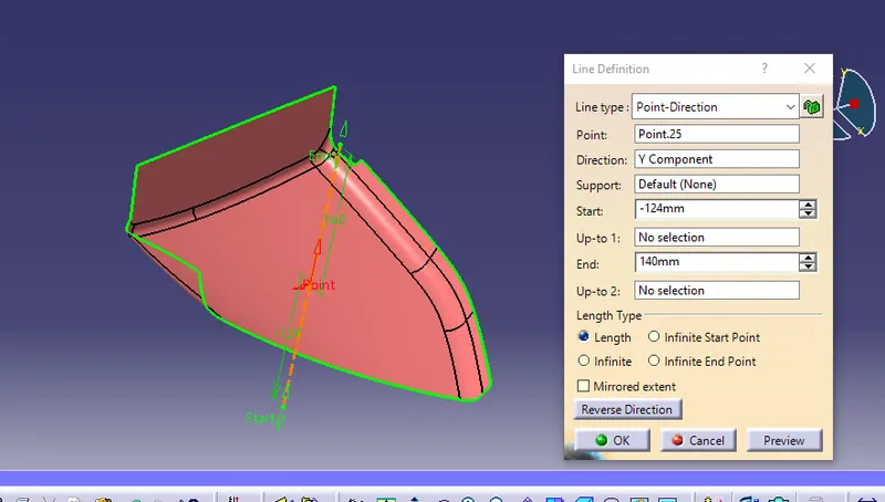
In case of the map pocket the we extract the surface in the Y direction orientation and use the point - direction to generte the tooling axis of the map pocket
Class A Draft Analysis:
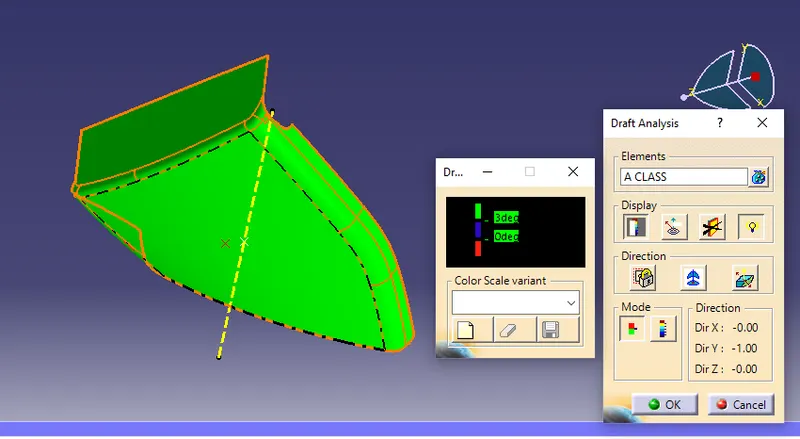
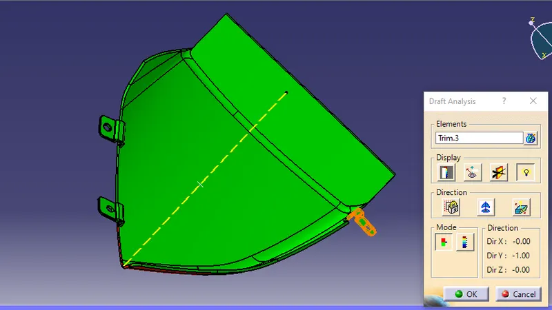
Once the tooling axis is create analyze the draft for the class A surface with a draft angle of 3 degrees.
Class B & C:
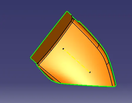
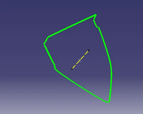
Now step forward to create the class B surface deploy the 2.5mm offset of the class A surface to generate the class B surface beneath the class A surface. Class A along the tooling axis direction and with a draft of 90 degrees along the reference surfcae sweep for C surface.
Final Join:
To join the Surface (A+C ) with the B surface.
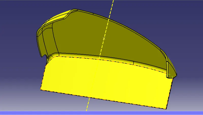
Close Solid Surface:
START -> MECHANICAL DESIGN -> PART DESIGN -> SURFACE FEATURE -> CLOSE SURFACE
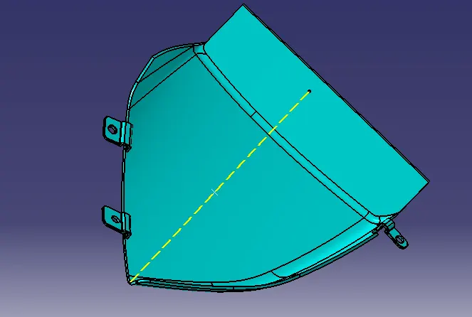
Map Pocket Draft Analysis:
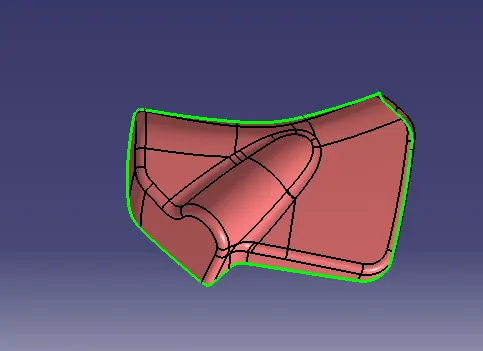
3. Bottle Holder:
class A:
Class A surface is the aesthetic skin data for the automotive part designing and curvature surface to represent the main component.Befor proceed with A surface to analys the Draft angle, if get any mis-match surface reconstruct the A surface.
Tooling Axis:
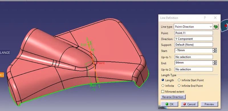
In the case of the bottle holder use the flat surface and extract the surface and create a point at the 0 coordinates and use the point - direction to create the tooling axis.
Class A Draft Analysis:
Perform the draft analysis of the class A surface with a draft angle of 3 degrees the result.
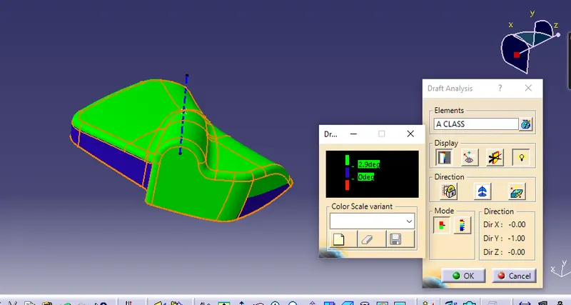
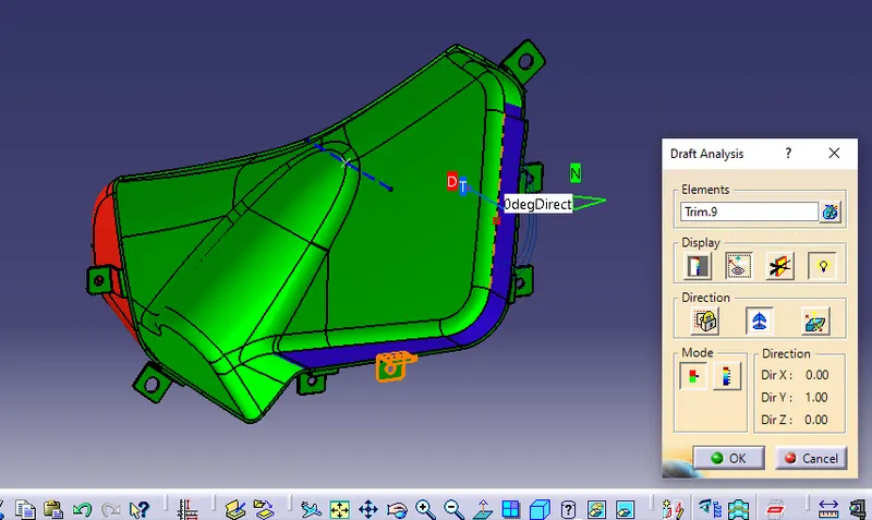
In the draft analysis some of the patches are red ( the draft is 0 or below zero ) and some in blur region shows that the draft is ( greater than 0 and less than 3)
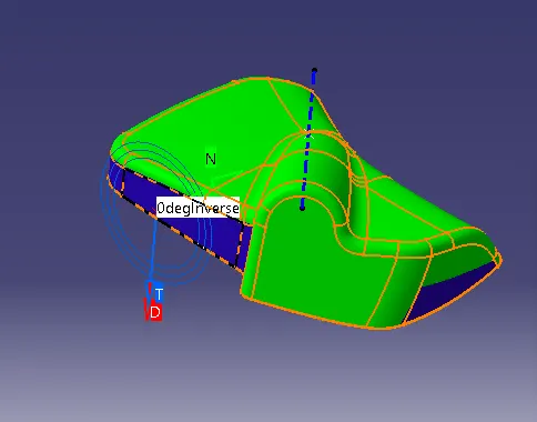
So we need to report to the class a team as te draft on the given input surface is not appropriate and need to get an update a class A surface So in this we need to continue forward with this draft analysis results for the further creation .
Class B & C:
To create the class B surface use the 2.5mm offset of the class A surface to generate the class B surface beneath the class A surface. Class A along the tooling axis direction and with a draft of 90 degrees along the reference surfcae sweep for C surface.
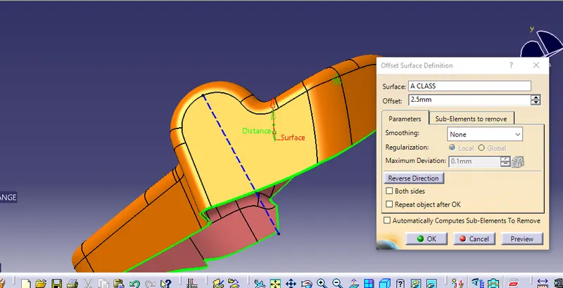
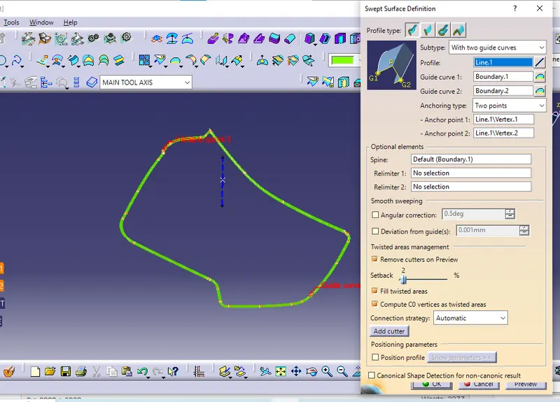
Create the boundary in class A and use sweep command with two guide curves method and sweep it and the C surface created.
Final Join:
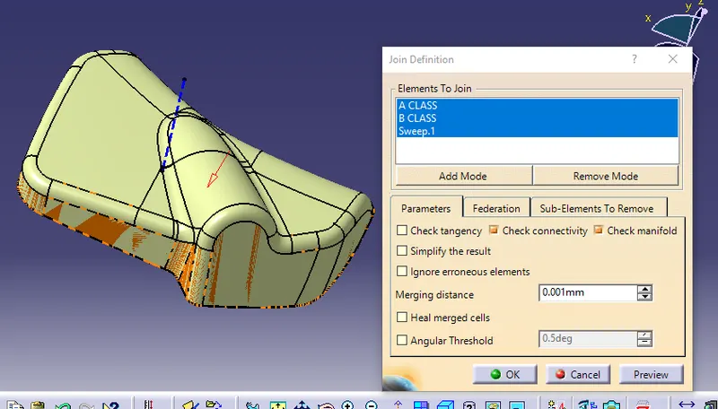
To join the Surface (A+C ) with the B surface.
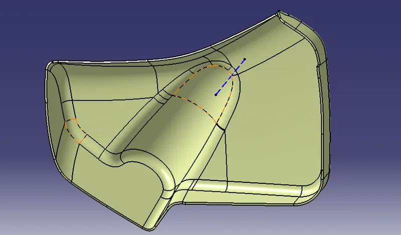
The Final close surface of bottle holder is
Close Solid Surface:
START -> MECHANICAL DESIGN -> PART DESIGN -> SURFACE FEATURE -> CLOSE SURFACE
Then create the flanges same like as the arm rest part.
Bottle Holder Draft Analysis:
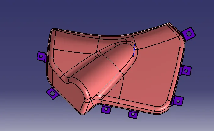
The blue area already explain in class A draft analysis,because Class A not clear the particular area because of the draft angle pf that area is 0degree.so final close body also not clear.Need to inform the Class A design team and improve the class A.
4. Lower Substrate
Class A:
Class A surface is the aesthetic skin data for the automotive part designing and curvature surface to represent the main component.Befor proceed with A surface to analys the Draft angle, if get any mis-match surface reconstruct the A surface.
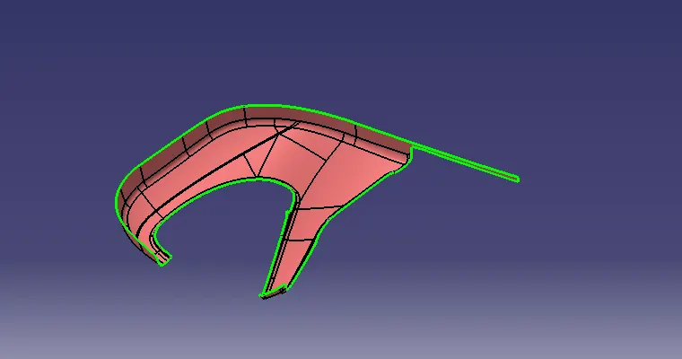
In this case of the door lower substract after examining the provided input surface we can able to detect a projection or an extension so we don’t need it for any further so, create a line and split the unnecessary surface
Tooling Axis:
In plastic design injection molding the Tooling Axis is the most important criteria. The tooling axis along to the core and cavity area, also the component ejecting ways of the core and cavity is most common in tooling direction only. For creating the tooling axis in this drill handle is differnt and very ease with comparing to the previous plastic component design.
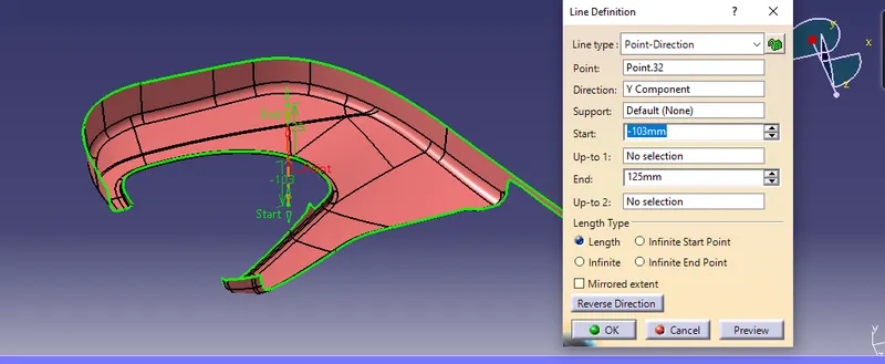
Here first created the point the option of point on curve to the class A surface and select the zero point.Then create the Line as point to direction and create the tooling axis
Class A Draft Analysis:
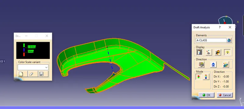
Draft is the main requirments in plastics molding. If the draft angle is less than 0 degree, the part or component and tool is to be damaged in mass production. If the draft angle is less than 0 degree, the part or component and tool is to be damaged in mass production. Also the molding part would not eject from the core and cavity. So the drafting analysis to find out the lesser angle are by the colour variation.
Class B:
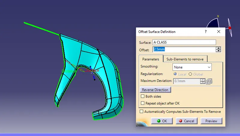
Here the lower substrate A surface is offset to 2.5 mm,and the no subelement is removed,so my class B surface is ready.
Class C:
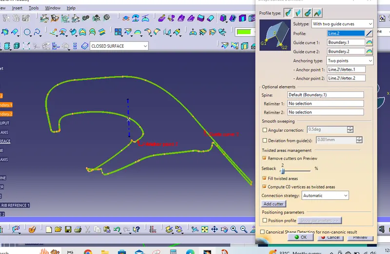
Create the boundary in class A and use sweep command with two guide curves method and sweep it and the C surface created.
Class A , B & C:
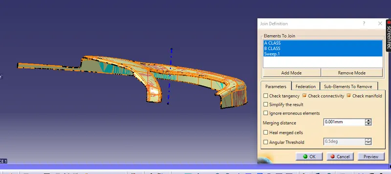
To join the class A, B and Class C surface by using join command the final Close surface was created.
Close Solid Surface:
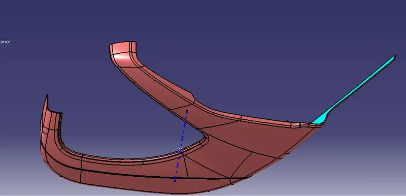
START -> MECHANICAL DESIGN -> PART DESIGN -> SURFACE FEATURE -> CLOSE SURFACE
B-Side Engineering Features:
- Dog-House
- Heat Stakes
- Ribs
- Locators
DOG HOUSE DESIGN:
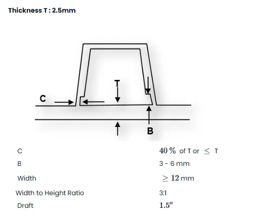
Dog house is an engineering feature used in the plastic trim design. Dog houses are used as supporting features. Sometimes other engineering features like boss; locators, etc. are mounded on them to increase their dimension and strength. Dog house and other engineering Features are built on final close solid body.
Design rules for Dog house creation
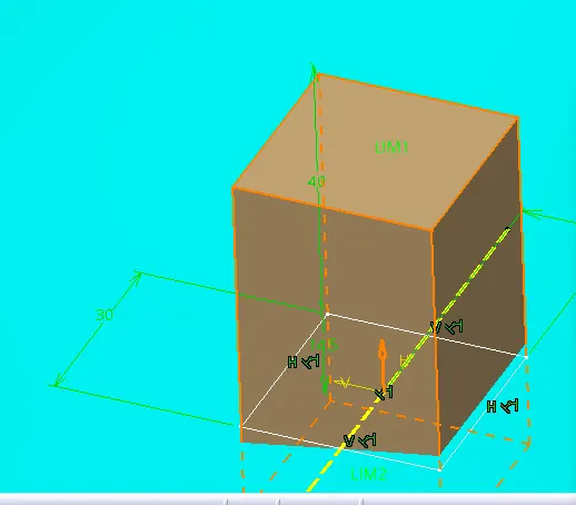
Create the sketch and draw the required shape of dog house and constrain all the dimensions.Then create the body and pad it.
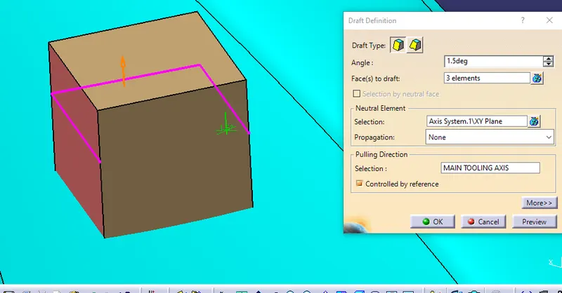
Draft the dog house body at the angle of 1.5° and the neutral element is plane, tooling axis is main tooling axis.
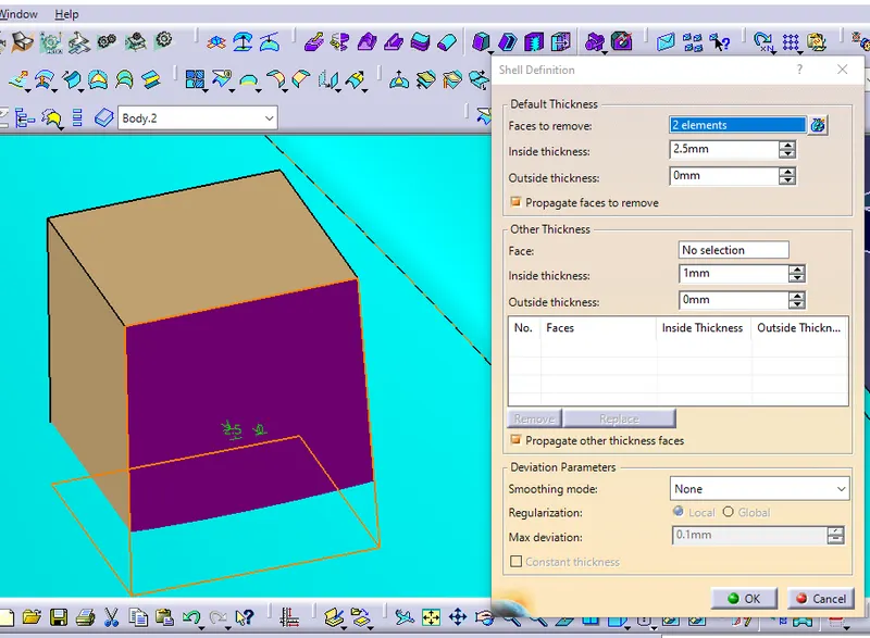
Make it shell and the thickness is same as the wall thickness of the closed body.
Ribs:
Create the sketch and project the master section and isolate for break the parent-children relationship between the master section and dog-house.Then constrain all the dimensions and create the body and pad it.
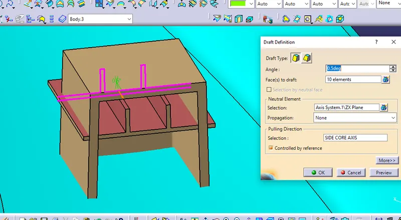
Make the side core and the top cut out for push pin area,and the dog house was created successfully done.
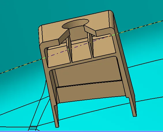
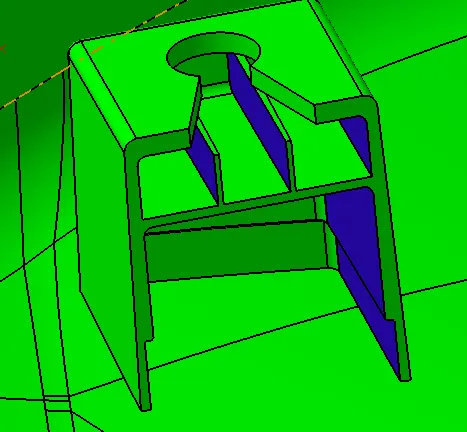
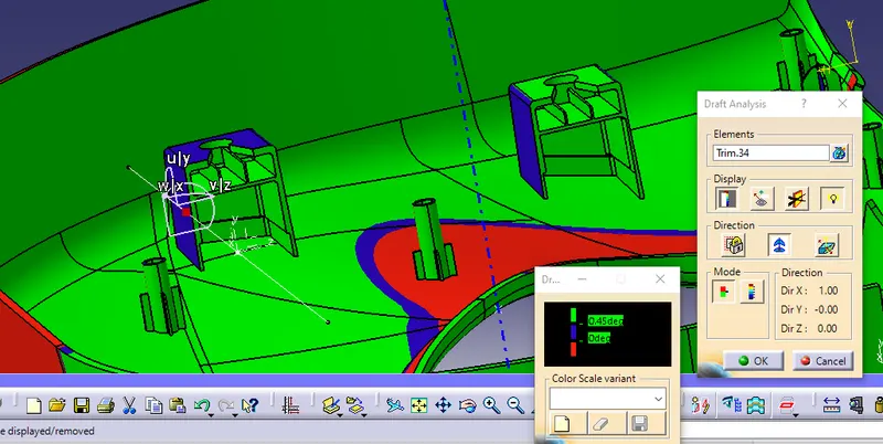
Dog-House Draft Analysis:
Heat Stakes:
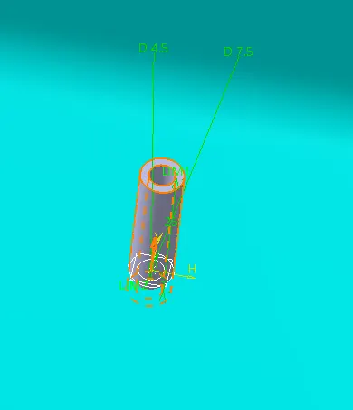
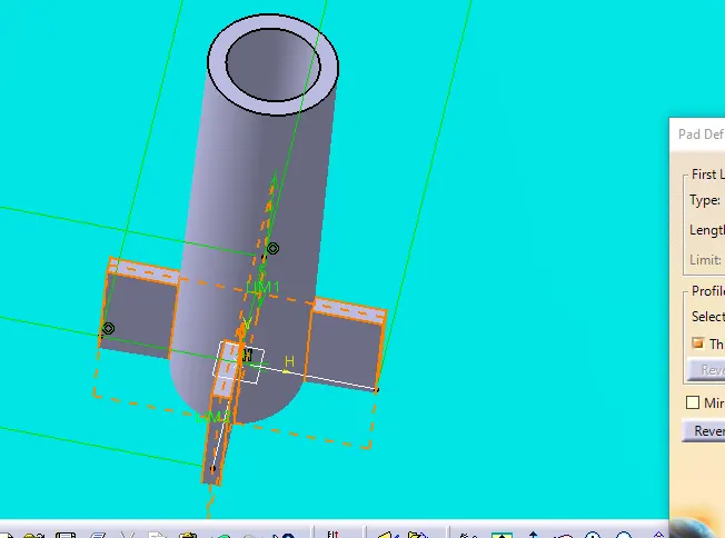
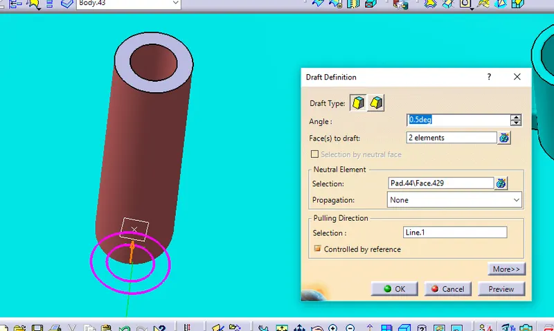
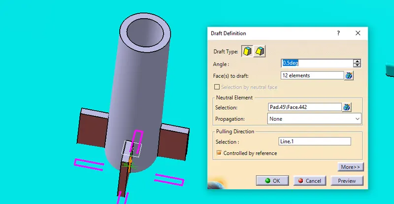
Plastic attachment industries currently use many different attachment methods to keep components together. Common fasteners such as bolts, screws, and rivets can be used to form permanent attachments, but there are attachment methods that don’t require secondary hardware. One of these methods is heat staking, which doesn’t required any additional fasteners.
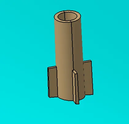
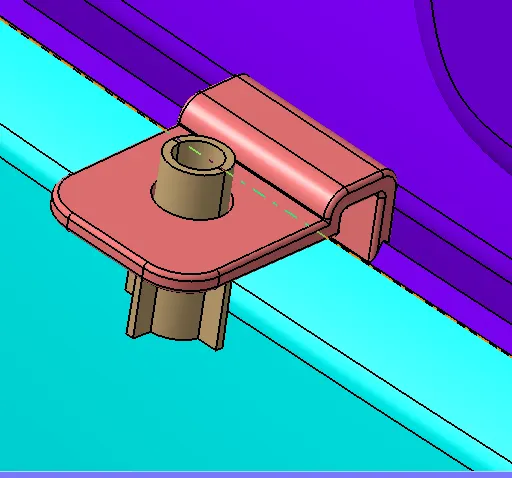
Heat staking is the process to attach two separate components together by melting the base plastic material into a shape that will hold the secondary component. It’s a permanent attachment method that does not require any additional material such as an adhesive or a solvent to make the permanent bond. The only addition is the heat applied to melt the plastic and a tool to shape the plastic to form the mechanical connection.
3-2-1 PRINCIPLE:
The work part free and it can move in an infinite number of directions. For analysis, this motion can be broken down into 12 directional movements or "degrees of freedom". All 12 degrees of freedom must be restricted to ensure proper reference of the work part.
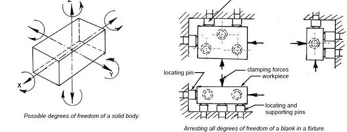
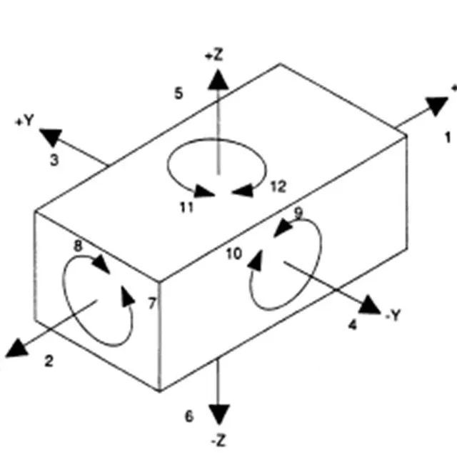
As shown in above figure, the 12 degrees of freedom all relate to the central axis of the work-part. Notice the six axial axis degrees and 6 radial degrees of freedom. The axial degrees of freedom permit straight-line movement in both directions along the 3-principle axis shown as X, Y & Z. The radial degrees of freedom permit rotational movement, in both clockwise & anti-clockwise radial directions around the same three axis.
4 Way Locator:
4-way locators mean you have to prevent the movement at 2 axes (+X, -X, +Y and -Y) on the plane. Generally, you have cylindrical pin on the fixture and circular hole at workpiece part.
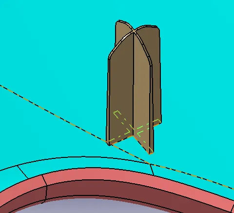
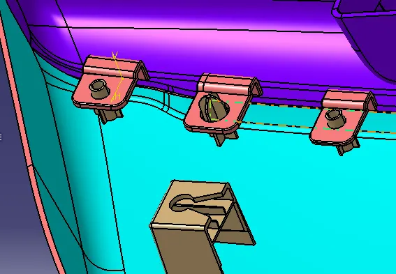
Draft Analysis:
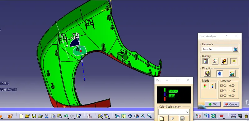
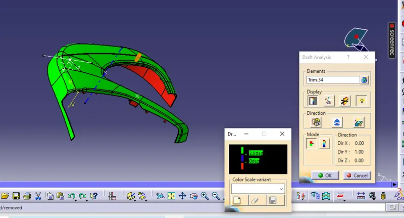
PUSH PINS- Push pins are used for joining one component to another . These are basically attached to the doghouse. For creating the push pins the following reference was taken for dimensions.
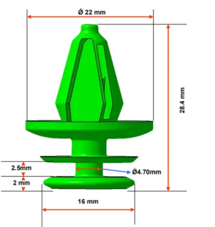
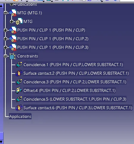
But here the push pin was given,so we need to constain and assemble with the door trim.
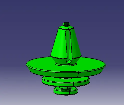
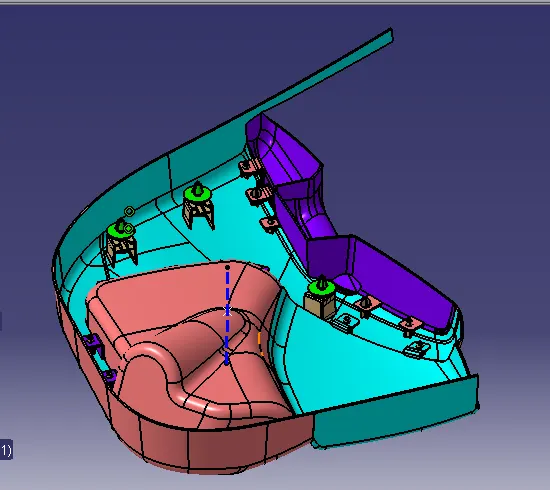
Assembly of Door Trim:
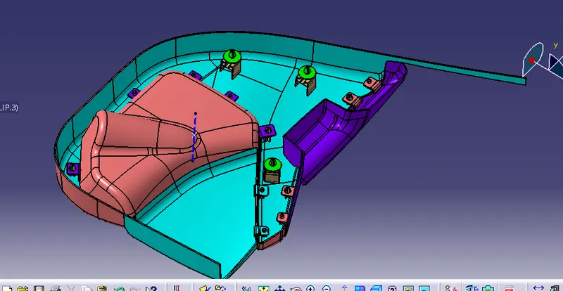
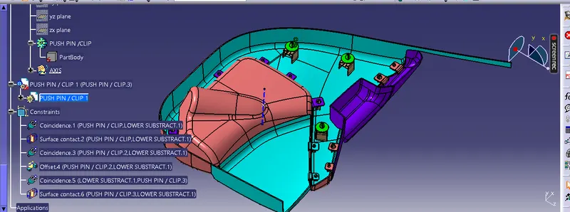
Parting Line:
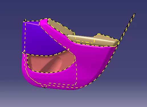
Different Views:
Front View:
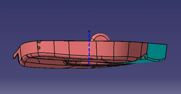
Side View:
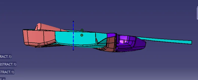
Top View:
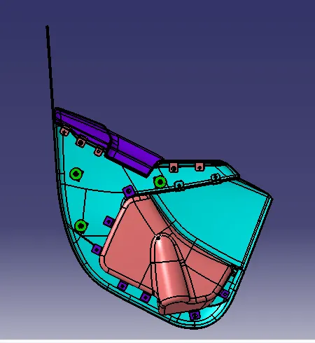
Iso View:
Conclusion:
The door trim panel was successfully created with all the design rules taken into considerations for feature attachment and the main part was created using the master section provided with the input class A.
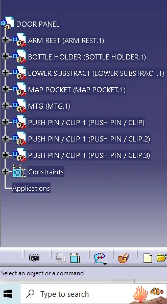
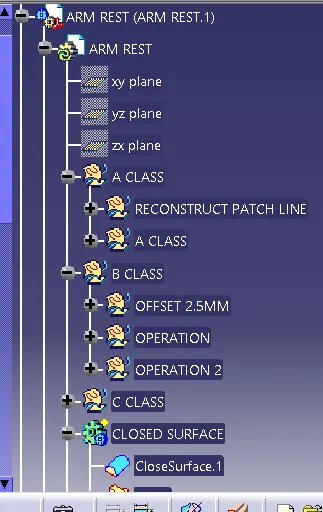
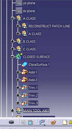
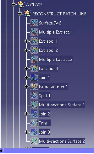
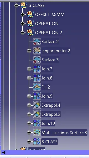
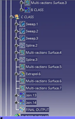
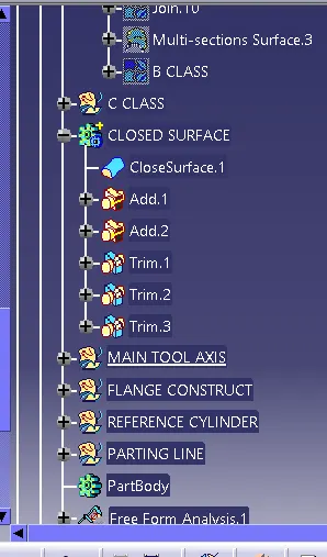
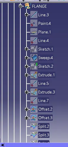
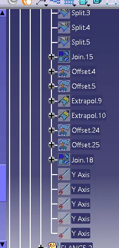
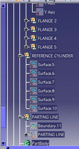
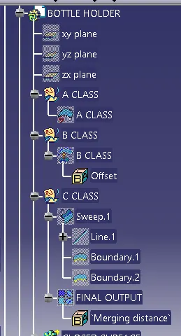
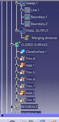
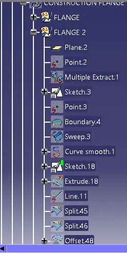
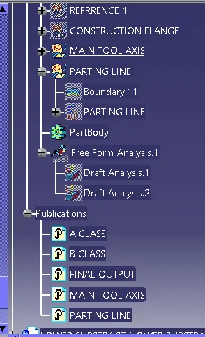
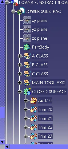
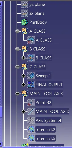
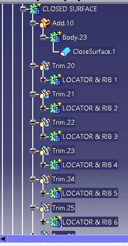
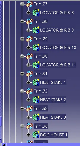
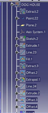
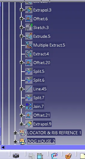
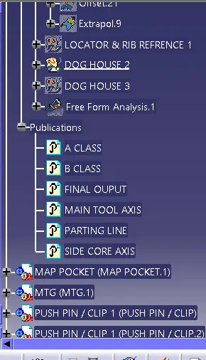
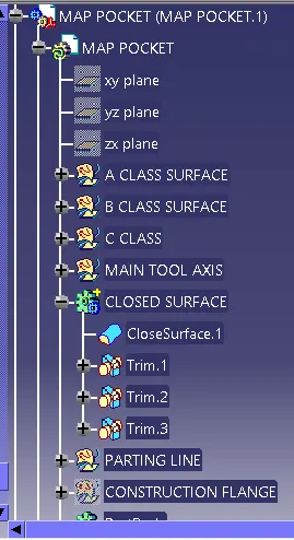
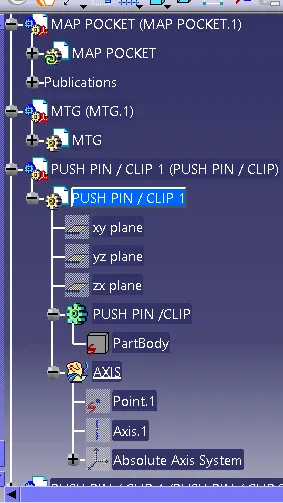
Tree Structures: