Week 12- Final project
FINAL PROJECT
DEVELOPMENT OF A DOOR TRIM PANEL
AIM:
To create a CAD model for door trim panel's parts by considering the given inputs of class A surface along with master section by following the design rules followed in OEM and tier1 companies.
OBJECTIVE:
- To create a TOOLING AXIS for all separate parts.
- Perform the DRAFT ANALYSIS for the all the CLASS A surfaces.
- If the CLASS A part was defective modify the CLASS A.
- Create a CLASS B and CLASS C surface.
- Make a closed body by using CLOSED SURFACE in the part design workbench.
- To create an engineering feature, on the b side surfaces.
- Perform the DRAFT ANALYSIS for the final part.
- Assemble all the parts together.
GIVEN DATA:
CLASS A SURFACE FINAL DOOR TRIM
The door trims are the interior parts that contain the most controls and decorative parts. As such, there is a necessity for balancing gap between parts, as well as an overall sense of unity between the numerous parts. The A-surface or the styling surface is first checked for any gaps and other issues in its surfaces. This Surface acts as the input surface so any correction to be done should be with approval from the styling team or done by them. A- perfect surface is the one when a boundary is created, the lines are only on the edges of a component and its holes or cutouts as shown below.
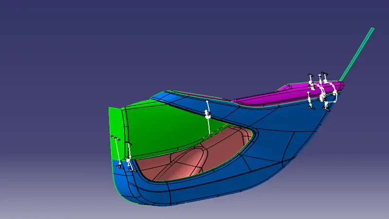
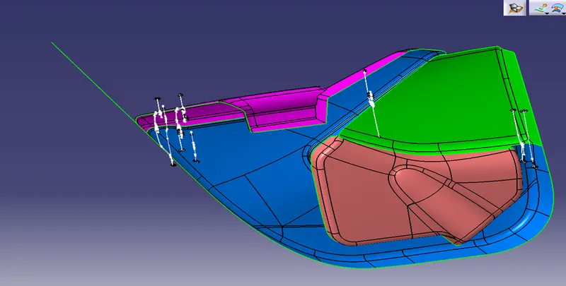
Create the engineering features according to the master section provided.
STEPS FOLLOWED TO COMPLETE THE PROJECT
- To check the given CLASS A surface for any modification needed if defect arises.
- To separate the four parts – ARM REST, MAP POCKET, BOTTLE HOLDER, LOWER SUBSTRATE from the given assembled class a surface.
- To create CLASS B, CLASS C individually for each part.
- Create a TOOLING AXIS for every part.
- Do a DRAFT ANALYSIS for every part.
- Create attachment features for all the parts on the CLASS B side surface.
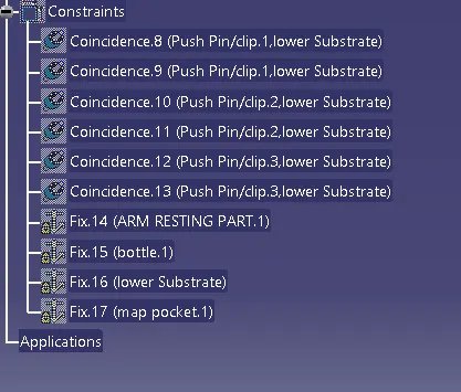
- Then do Draft analysis on final parts and then constrain them for assembly.
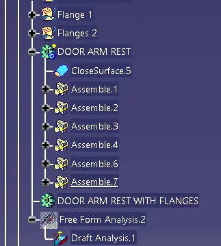
ARM REST DESIGN
In the front of the car, a central armrest, which commonly folds away based on user preference, will also often include a storage compartment and sometimes even cup holders.
CLASS A SURFACE
We cannot proceed with the CLASS A surface because there is defect in the CLASS A surface. For that we want to correct the CLASS A surface. CLASS A surface can be corrected by using extrapolate,trim by creating boundary.
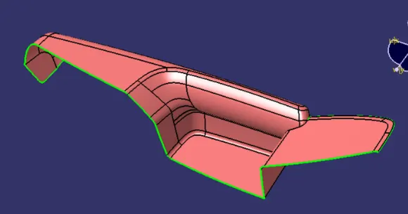
This defect was seen in the class a surface.So we want to close the extra boundary.
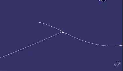
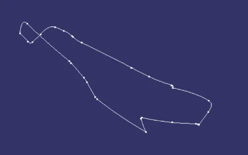
After completing the patch works check whether there is any open boundaries are there.
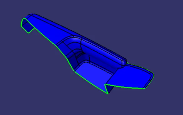
There is no open boundaries.So now we can move on to create the class b and class c surface.
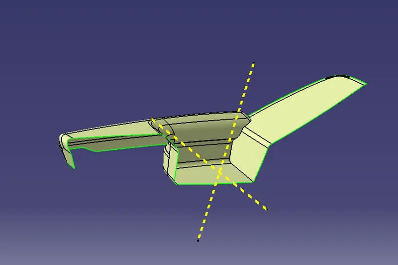
TOLLING AXIS CREATION
For arm rest side and main tooling axis should be created.
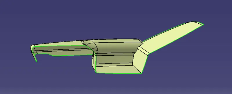
CLASS B SURFACE
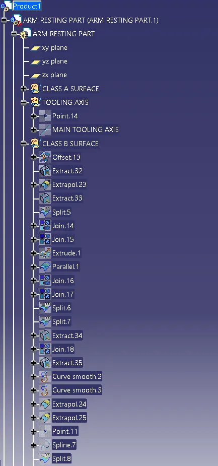
Class B surface was created by offsetting the class a surface.
CLASS C SURFACE
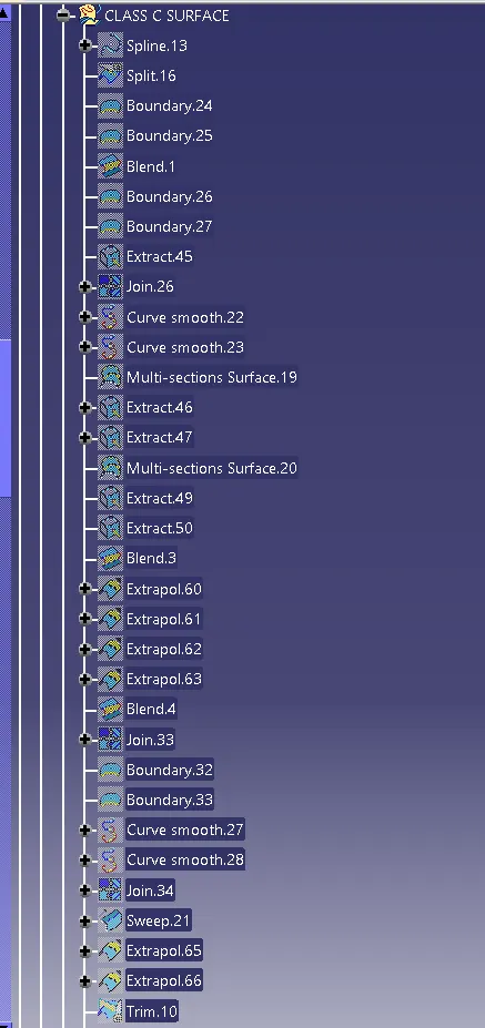
For CLASS C surface creation create a boundary from the CLASS A surface and give a sweep command and join the CLASS A and CLASS C surface by using join command.
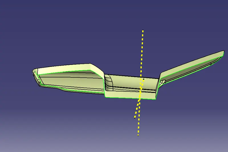
Then create a part body using CLOSE SURFACE in part workbench.
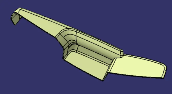
ATTACHMENT FEATURE CREATION
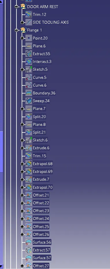
Create a flange in the closed body with reference of master section.
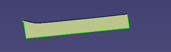
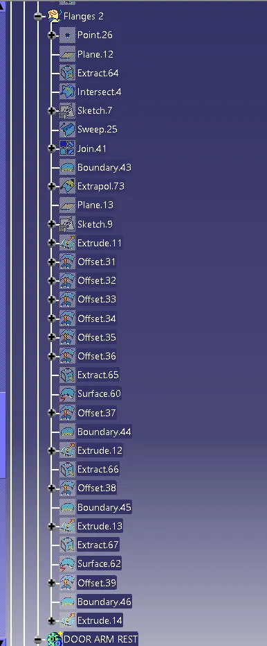
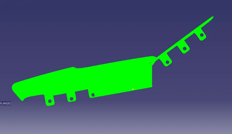
Create a flanges on the both sides of the arm rest.
The draft provided is 0.5 deg
Apply required fillets on all the sharp edges.
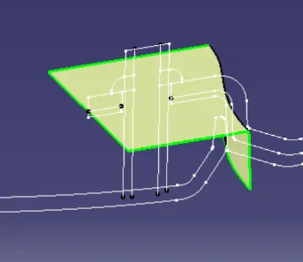
Thicken the surface in the part workbench with 2.5mm.
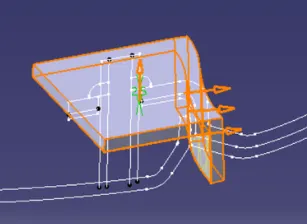
Then assemble all the flages to the arm rest part body.
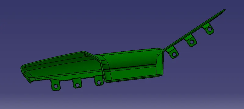
DRAFT ANALYSIS FOR THE ARM REST
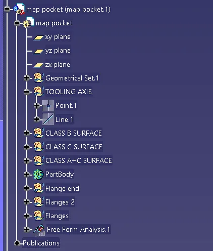
MAP POCKET DESIGN
GIVEN CLASS A SURFACE
We can proceed with the CLASS A surface because there is no defect in the CLASS A surface.
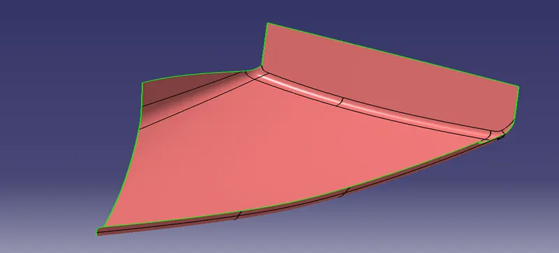
Create a TOOLING AXIS by creating the point and line definition.
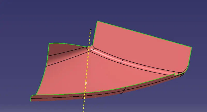
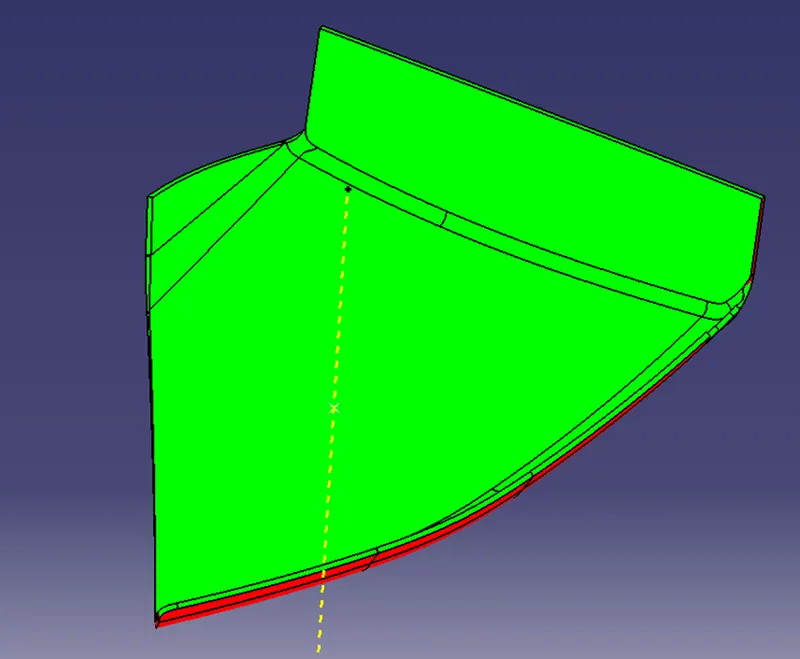
Do DRAFT ANALYSIS for the given CLASS A surface.
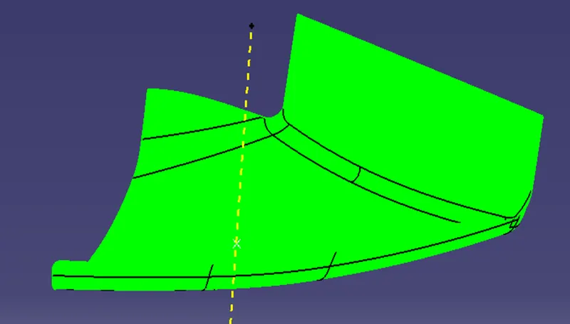
CLASS B SURFACE
- For creating a CLASS B surface make an OFFSET for the CLASS A surface.
- While offsetting some patches are created in the B SURFACE.
- For that use MULTISECTION SURFACE option and JOIN to the CLASS B surface.
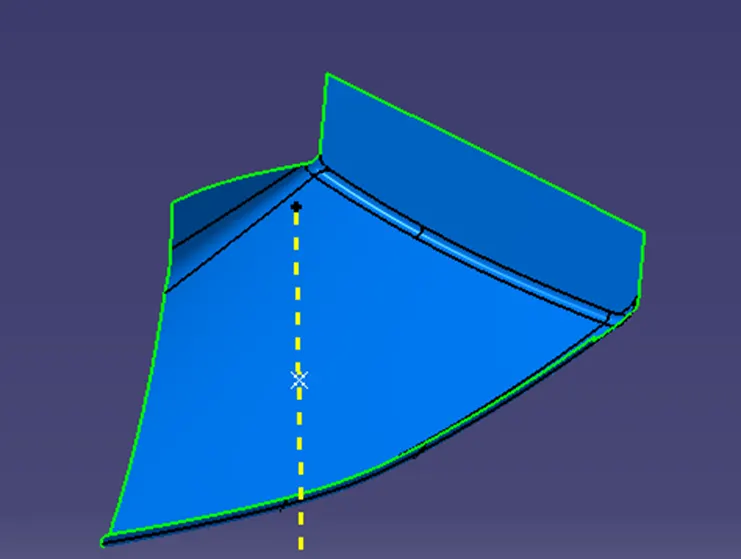
CLASS C SURFACE
- Create a CLASS C surface from the CLASS A.
- Create a boundary and give sweep option for all the edges of the CLASS A.
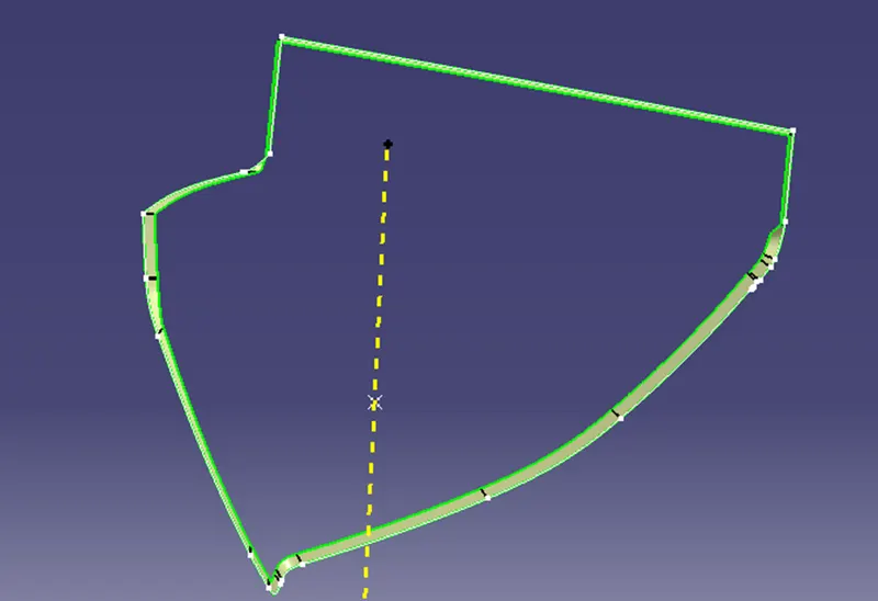
CLASS A+C SURFACE
- Using JOIN command join the CLASS A and CLASS C.
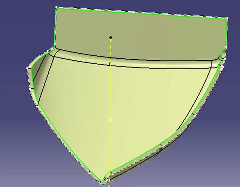
CLOSED BODY
- Check whether there is open boundary are there.
- If there is no boundary go to the part design and make a closed surface.
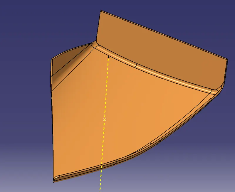
DRAFT ANALYSIS FOR THE PARTBODY
FLANGES
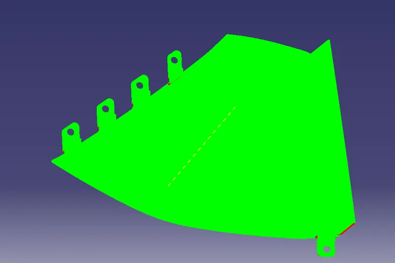
create a flange for the map pocket.
Flanges are the joining features that help to assemble different components. The master section was used to make flanges. After creating one flange point to point translation is used to translate the flanges. We need to provide a draft of 0.5 degrees for the flanges. The gap between flanges should be 50-100 mm. Boolean operations were used to add attachment features into closed body.
In case of the door map pocket , we need to follow the master section provided for the flange creation The thickness of the flange is equal to the thickness of the plastic component that is 2.5 mm.
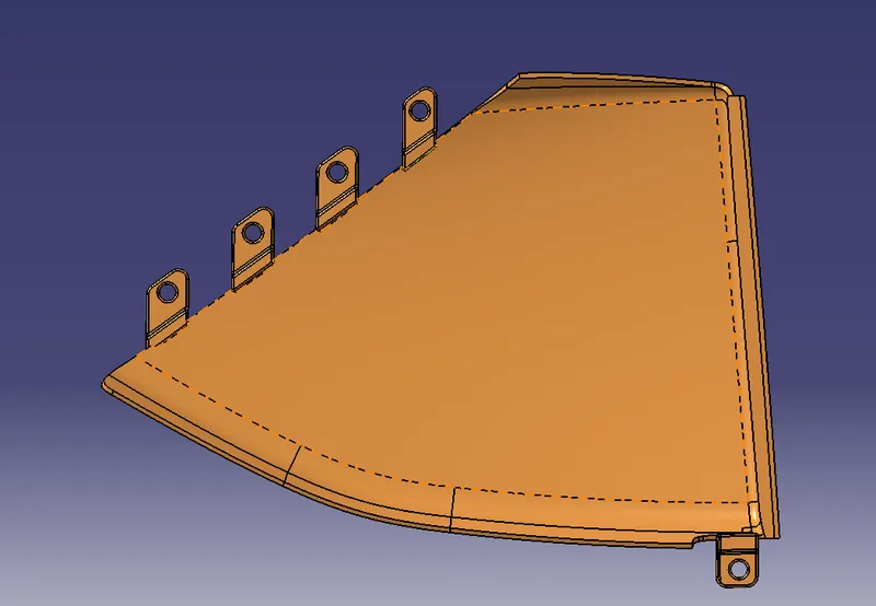
DRAFT ANALYSIS FOR FINAL PART BODY WITH FLANGES
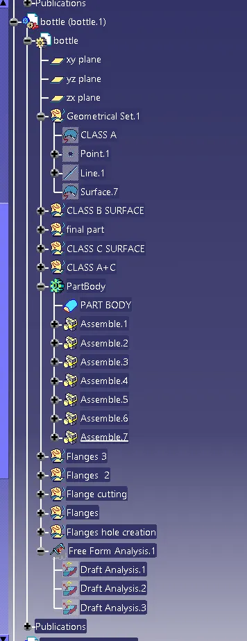
BOTTLE HOLDER
GIVEN CLASS A SURFACE
There is a defect in the CLASS A surface but there is minimum defect only so we can proceed with the given CLASS A surface.
Create a TOOLING LINE for the surface.
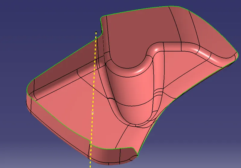
DRAFT ANALYSIS FOR CLASS A SURFACE
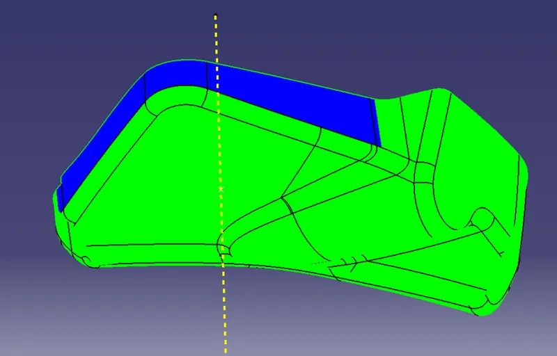
CLASS B SURFACE
- To create a CLASS B surface offset a CLASS A surface to a distance of 2.5mm.
- Check if any patches are created while offsetting a CLASS A surface.
- If there are no patches continue to create a CLASS C surface.
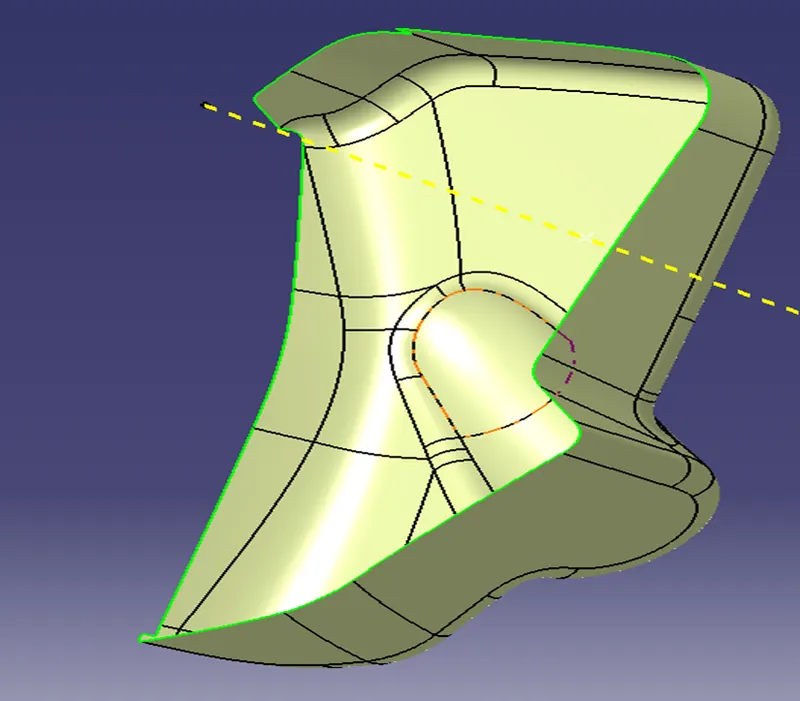
CLASS C SURFACE
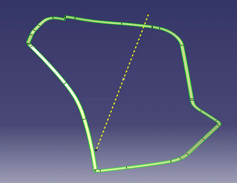
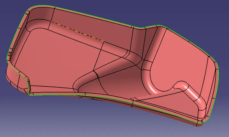
- Hide the CLASS B surface and unhide the CLASS A surface to create a boundary on the CLASS A surface.
- Then using SWEEP option sweep the boundary to 90 degrees.
- Then join the CLASS A surface and CLASS B surface.
CLOSED BODY
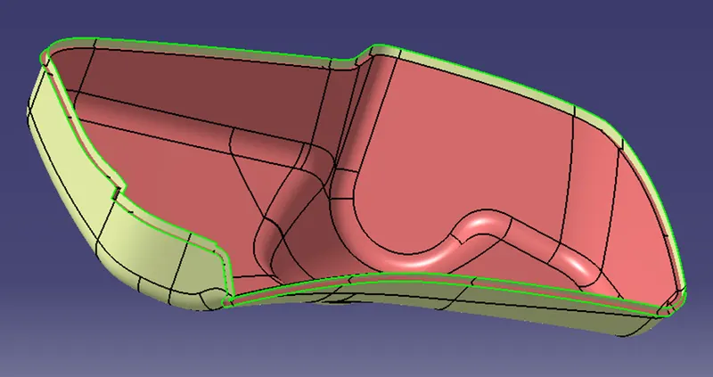
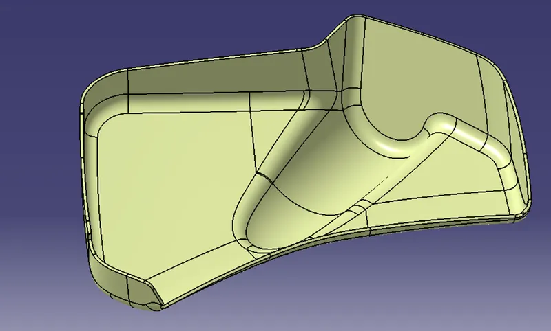
- Extrapolate the CLASS B surface by creating the boundary.
- Then by using TRIM option trim the CLASS A+C and CLASS B extrapolate.
- Check whether there is any boundary are open.
- Finally go to the part design workbench and click the closed surface option and make a final part body.
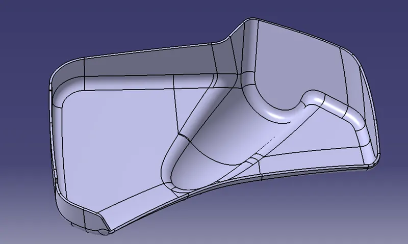
DRAFT ANALYSIS
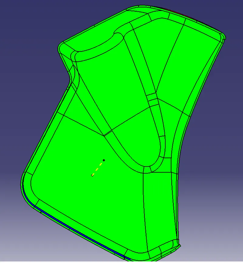
There is a defect in the CLASS A so some part are not drafted properly.
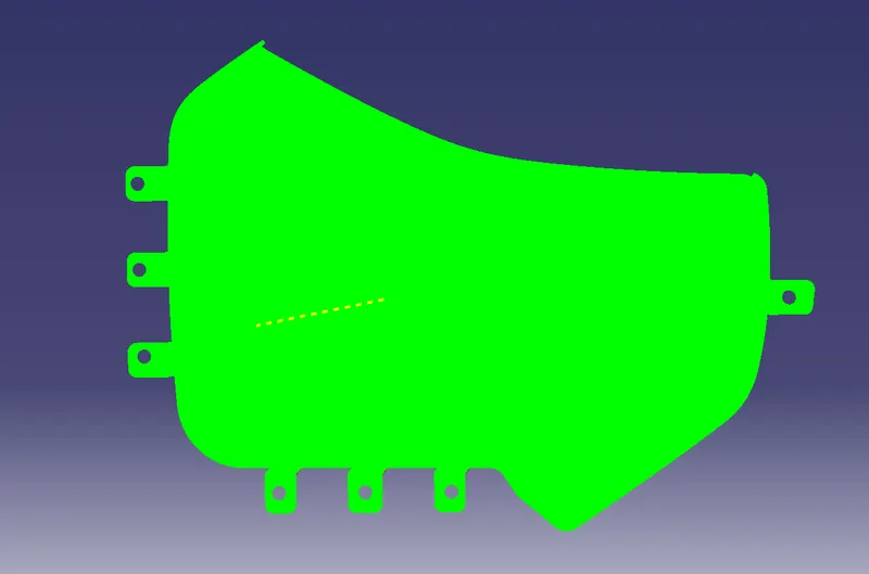
DRAFT ANALYSIS FOR FINAL PART PART BODY WITH ATTACHMENT FEATURES
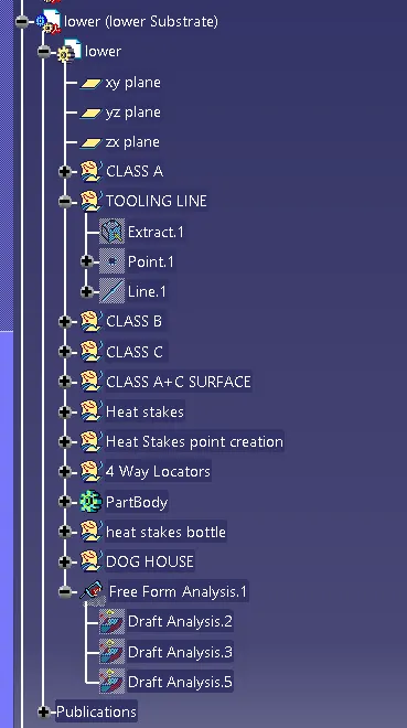
LOWER SUBSTRATE
GIVEN CLASS A SURFACE
There is no defect in the CLASS A surface it looks look perfect while seeing on DRAFT ANALYSIS.
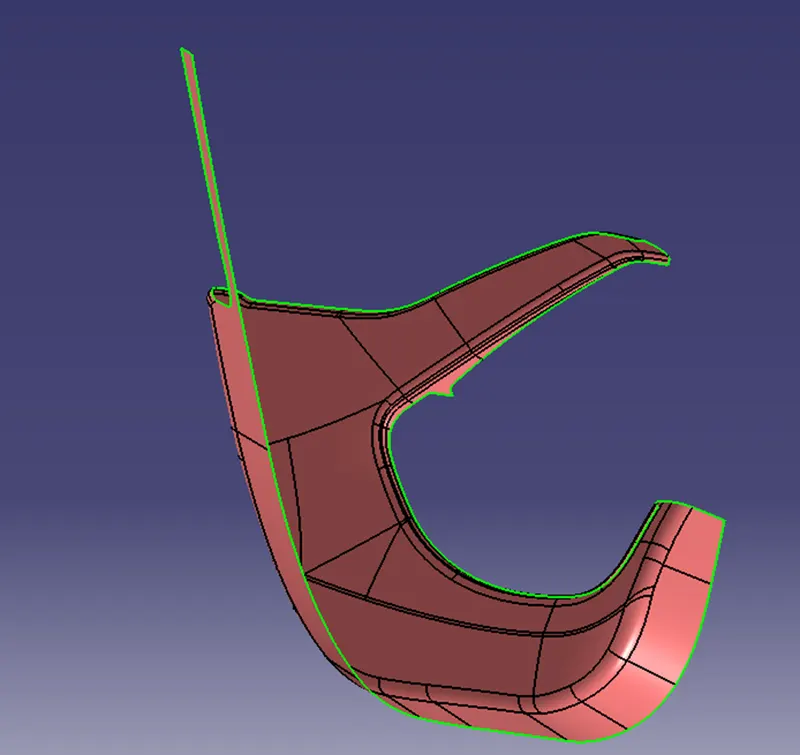
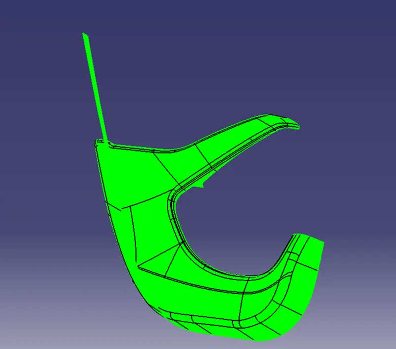
TOOLING LINE CREATION
Create a TOOLING AXIS before draft analysis by creating point on the surface and create a line with POINT DIRECTION.
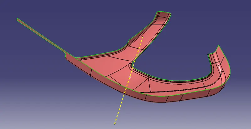
CLASS B SURFACE
- CLASS B surface was created by offsetting the CLASS A surface to 2.5 mm.
- There is no patches created while offsetting the CLASS A so there is no repairing needed.
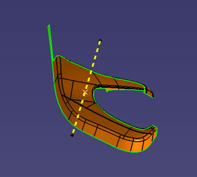
CLASS C SURFACE
- First hide the CLASS B and unhide the CLASS A surface and create a boundary for the CLASS A surface.
- Now go to the SWEEP option and select that boundary and sweep it to 90 degrees.
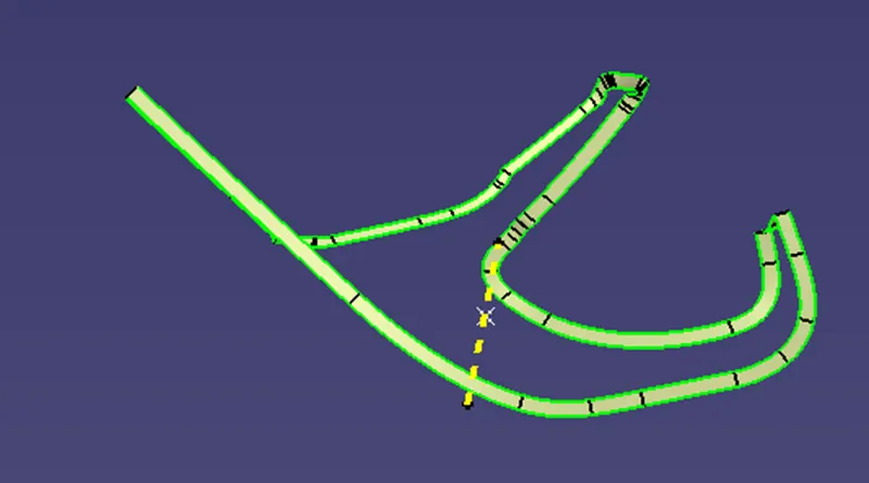
CLASS A+C JOIN
- Join the CLASS A and CLASS C using JOIN option.
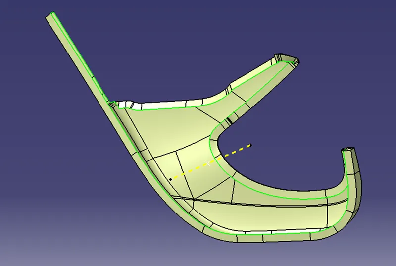
Final part body
- First create a point in the lower substrate on the required distance for four way locators,heat stakes and dog house.
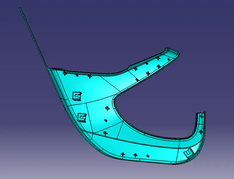
DRAFT ANALYSIS
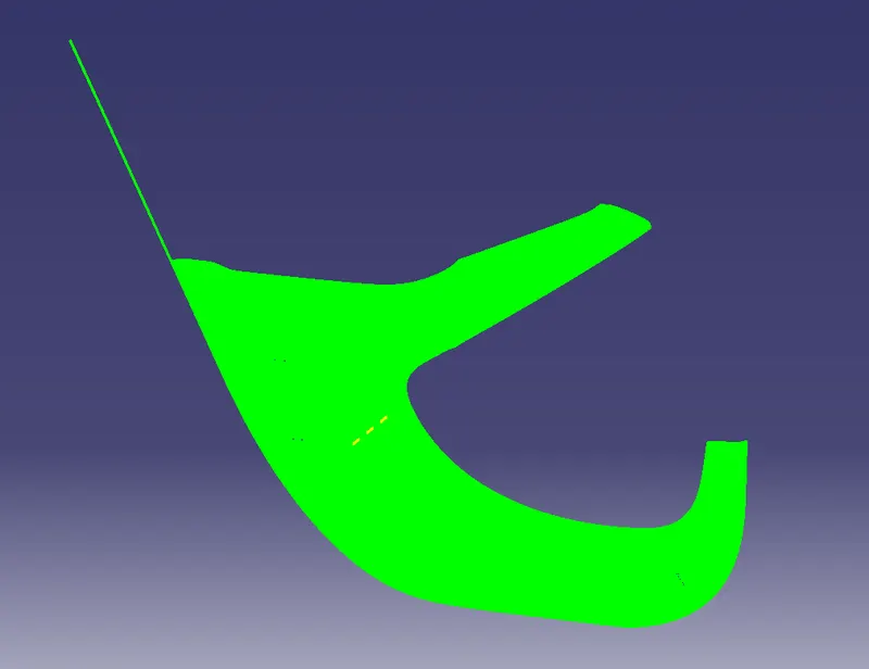
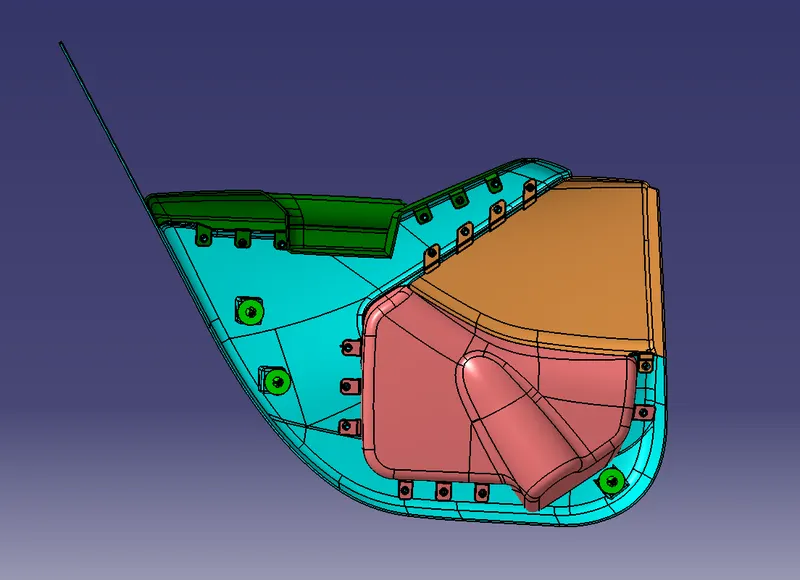
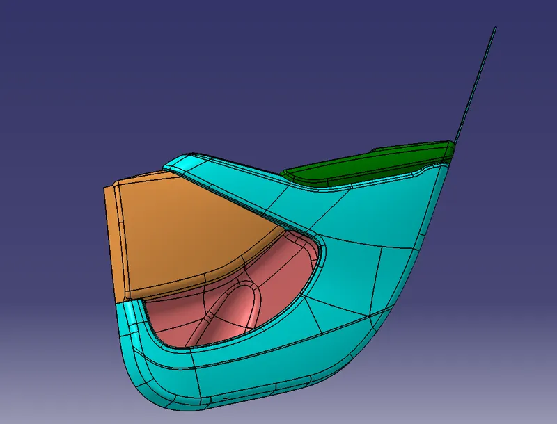
FINAL ASSEMBLY