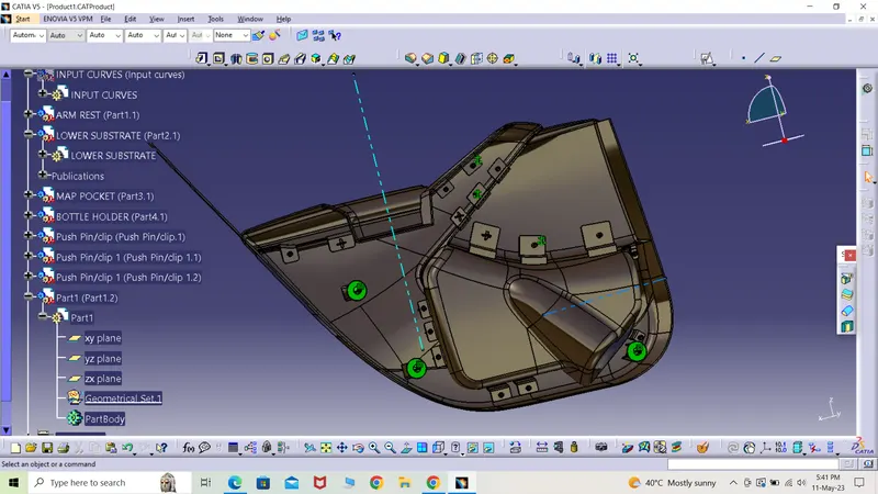
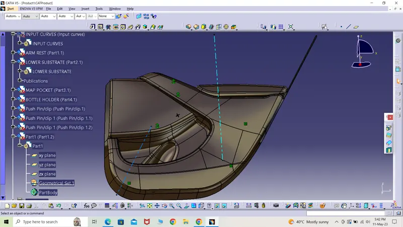
Week 12- Final project
Side door is a component of a car that is used to enclose the passenger and luggage in the car as a matter of safety. There are 5 close open compenents in a car. Four doors,hood,back door and fuel gate.
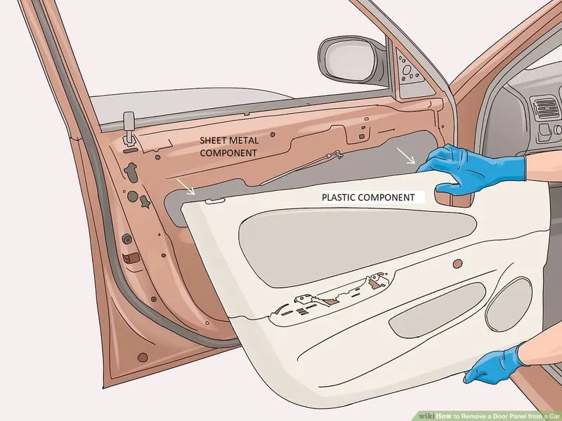
A vehicle door is made up of metal and plastic surface. The outer region of the door is made of sheet metal which has outer and inner panel. The surface of the door that is visible to the passenger when sitting inside the same is called inner door trim. It is made of several other trims and this particular part is the lower door trim. It consists of features that help in plummeting the drivers comfort by having different sections to hold object in place and control switches of music system and other door control operations. Most of the inner trims have soft portion with a cushion on them. The cushion regions are wither stapled or glued on the main plastic component.
Inner trims of a car door consists of several components like map pocket, bottle holder, lower and upper substrate, arm rest, door handle release.
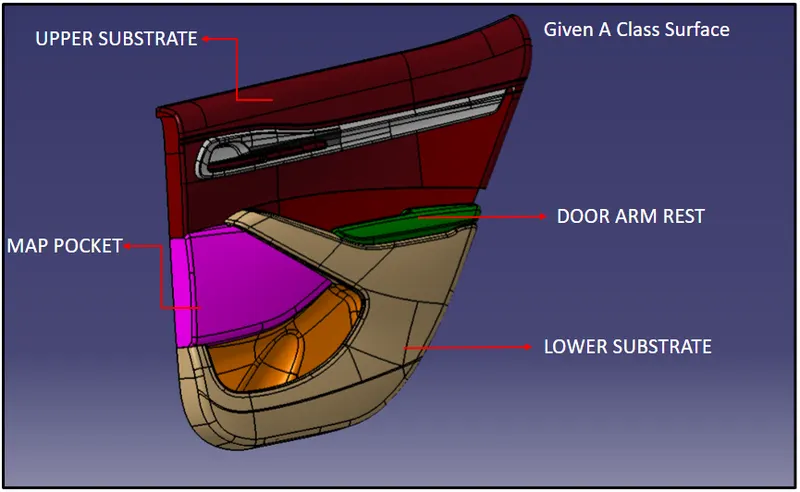
All the aforementioned components are connected together by flanges and heat stakes and locators. These are present on all the four door. Arm rest contains switches that control all the door controls, music, safety systems. Bottle holder is given to hold the bottle, prevent it from falling out of the same door. Map pocket is given to prevent the unnecessary movement of the bottle holder while driving. Lower and upper substrate are the big structure that give support to the other components connected to it.
RIBS
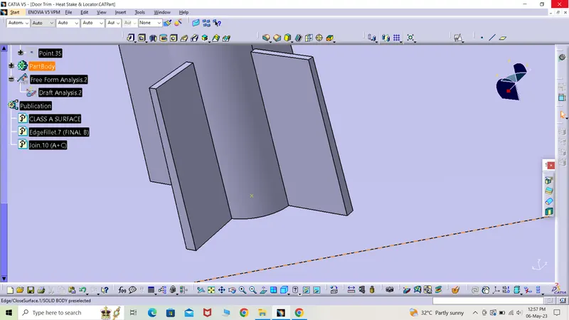
Ribs are given to the part which would face forces and stresses that may break the angled edges. Ribs give strength to the angled edges without increasing the wall thickness. These also assist in locating and arresting components of an assembly. These are also given to align the mating part. These are act as stop and guide mechanism while fitting two parts. Ribs often cause sink marks. Highly glossy material is used to create a thin ribs. Rib thickness directly affects the mouldablitly. Very thin ribs can ve different to fill.
*) In several product manufacturing, it is often necessary to join thermoplastic components with dissimilar components.
HEAT STAKES through the application of heat is used combine plastic parts with other components that are made up of other materials like steel. Staking is the process to combine components made of desimilar materials. The molted plastic parts combine a projection which is melted and fills the volume of the forming tool cavity which in turn produces the head to lock the other part.
The protruded plastic that is there on the base part is allowed to fit into a hole of the other part of other material. The protruded plastic then gets melted by exerting high pressure along with heat that turns the protruded surface into a shape as shown in the pic to lock both the parts tightly and hence the parts are joined together.
LOCATORS
A part has a total of 12 degree of freedom as shown in the pic below. A part that has to be worked upon on a tooling workbench for machining or welding should be fixed to restrict all the 11 d.o.f. mentioned the movements.
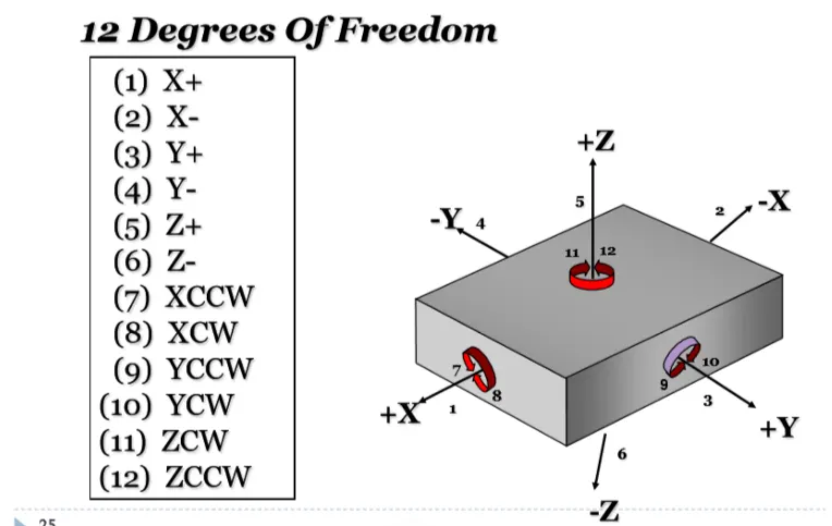
A component or part usually has several such locators that helps in perfect fixing of the same onto another one and holds it while the component goes through several stress applications. There are two types of locators which are 2-way and 4-way locators. A 2 way locator restricts less degree of freedom than a 4 way locator. Locators must be always longer than heat stakes as the past should align and arrest first and then fastened or fixed.
*) There are many defects that can enter in the final plastic part which are flashes, short short, burn marks,voids, sink marks,weld lines,flow lines. Amongst all, sink mark is the most common one and that must be avoided.
*) Sink marks are the depressions or craters that develop at thicker areas of prototype which shrinkage occurs on inner protion of the finished product.
Causes
1) Insufficient cooling time.
2) Inadequate cavity pressure
3) Varying part thickness
Remedies
1) Give enough cooling time.
2) reduce variation in the thickness.
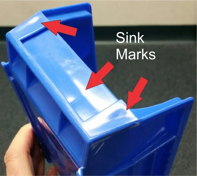
*) To avoid such defects, dog house is given and the other engineering features like rib, locator, heat stakes are designed according the safe design parameter.
*) Dog house is an engineering feature created on B surface of plastic parts to avoid sink marks that are shown above. It is also given to avoid adaptation of large screw boss height which is liable to break easily under stress developed at the time of movement of the vehicle. So if a region require a screw boss of longer length then a dog house is created first of a certain height and on the top of the same, screw boss is created. It is subjected to draft analysis in order to prevent the part from getting damaged at the time of ejection.
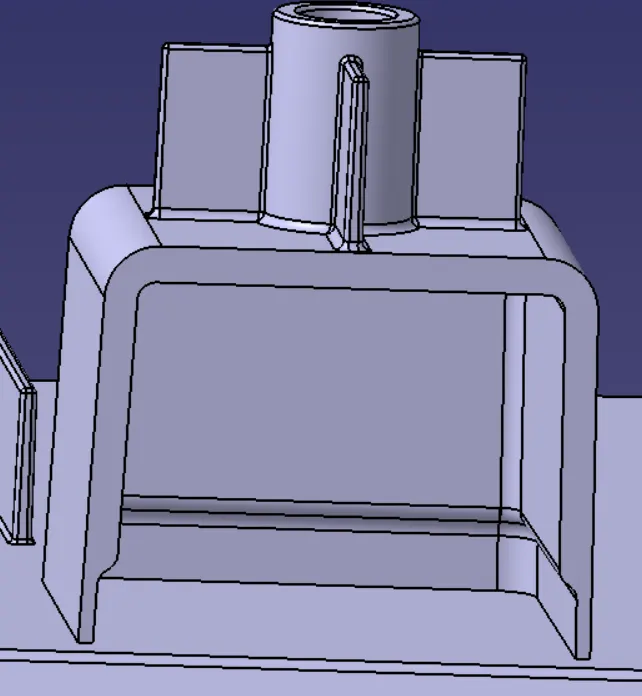
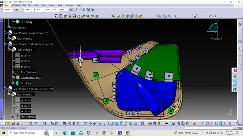
*) On the top of the dog house, locators, ribs, or push clips may be given as per the demand. In this project, slider dog house is used to give a plastic push clip to fix inner panel with the outer door panel. Somwtimes, ribs are also given to the dog house to provide strength to the same. To avoid sinks marks, there is a lower section of the dog house that is given by reducing the thickness of the same as shown in the pic above.
MASTER SECTION
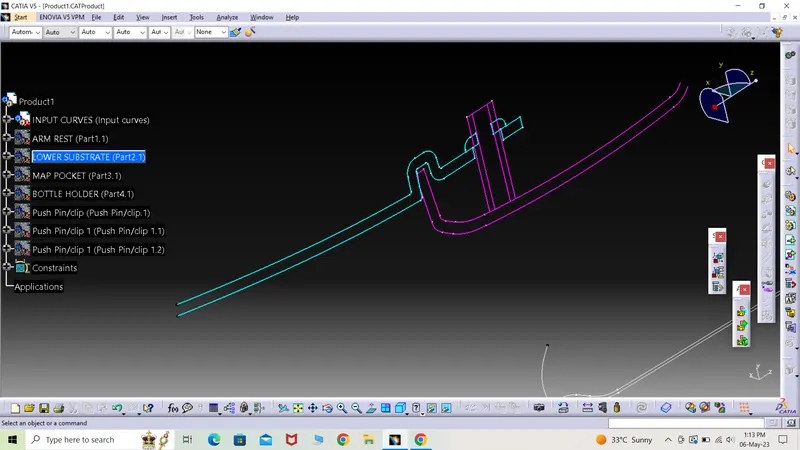
Master section gives these information:-
*) Master section is the outline or intersection, cross-section of the part that needs to be produced.
*) Master section includes thickness of the parts.
*) Surface on which the part lies.
*) Engineering process used to produce it.
*) Gaps and dimensions of the part.
DESIGN OF THE PART IN CATIA V5
*)There were several parts involved in this project, the design was done by opening the parts one by one as a product. This was done in assembly design mode.
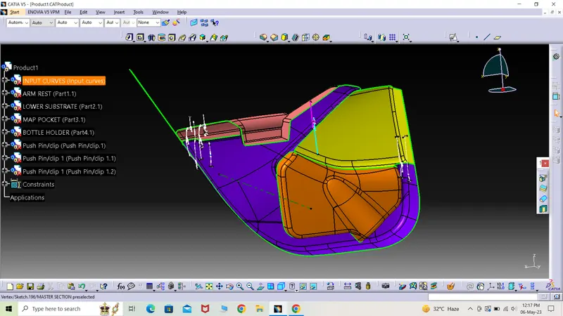
*) Master section was given with the remaining surface A class.
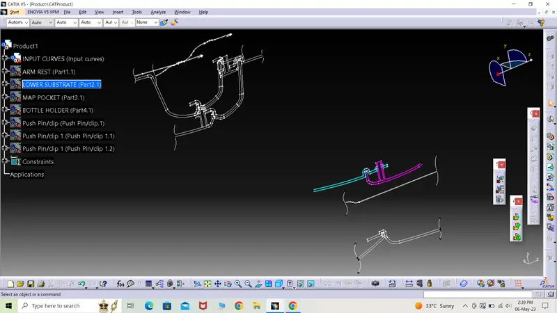
*) The same design technique was used to create this part in which a class A surface was given and with the same, class B and C surface were created and then joined together.
LOWER SUBSTRATE
*) Class A surface was already given so by creating the boundary, the whole outline of the body was obtained to study the surface quality of the surface which was OK as there were no discontinuity in the boundary and was neat. So that the same surface could be referred to create the other surfaces. 
*) A geometrical set by the name tooling axis was created.
*) The surface was observed in different views. The surface with large surface area visible when seeing from tooling axis has to be considered for a proper manufacturing of the final part.
*) A flat surface was extracted and then a point was created on it. A line was created by using point direction option. This was treated as the main tooling axis for the particular part.
Draft analysis of CLASS A surface with normal to surface line as tooling axis
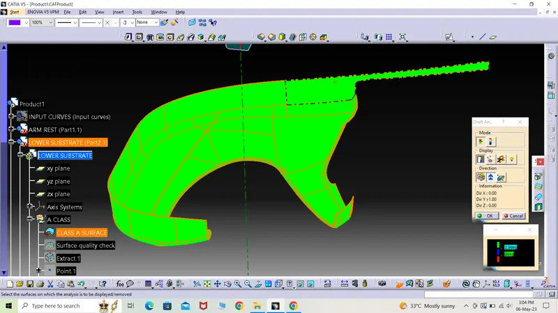
*) The surface is absoulutely OK and passes the draft analysis with value 2.9 degrees.
CLASS B SURFACE CREATION
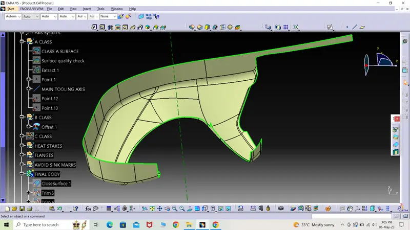
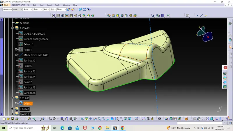
*) The part was offsetted towards inside to 2.5mm which is the desired thickness of the final part.
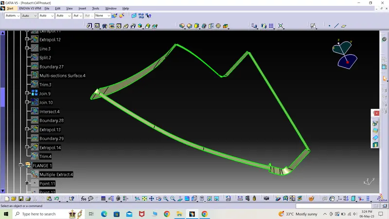
*) There were some regions with gaps in between which was highlighted with the open surface colour i.e. green.
*) The gaps were extracted and expolated to intersect with the adjacent edges and later were trimmed together.
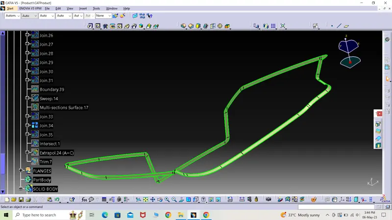
CLASS C SURFACE CREATION
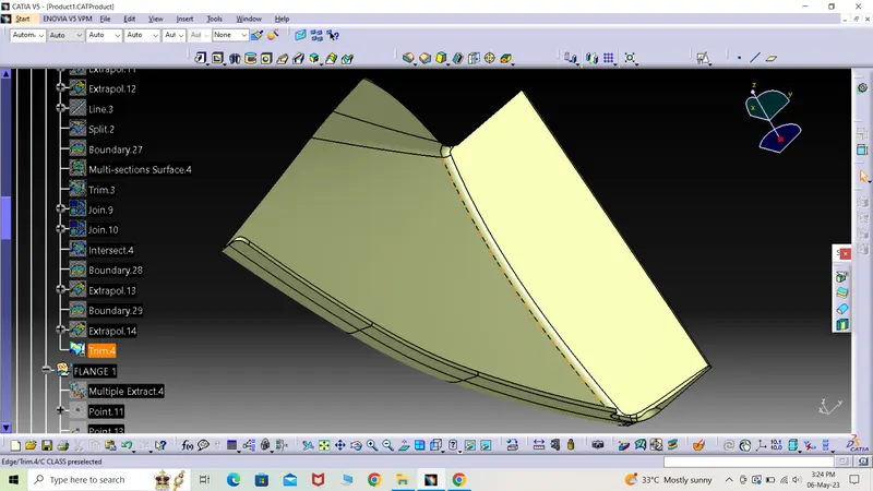
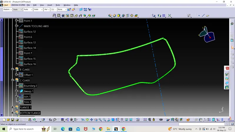
*) Swept with surface reference was used as command to create the c surface with the reference of class A surface.
*) Extra regions were later trimmed or joined.
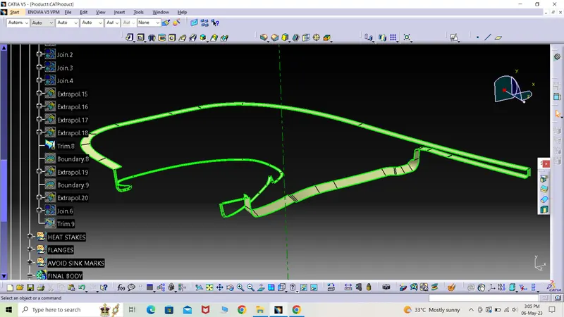
*) Class A and C were joined together to form A+C surface.
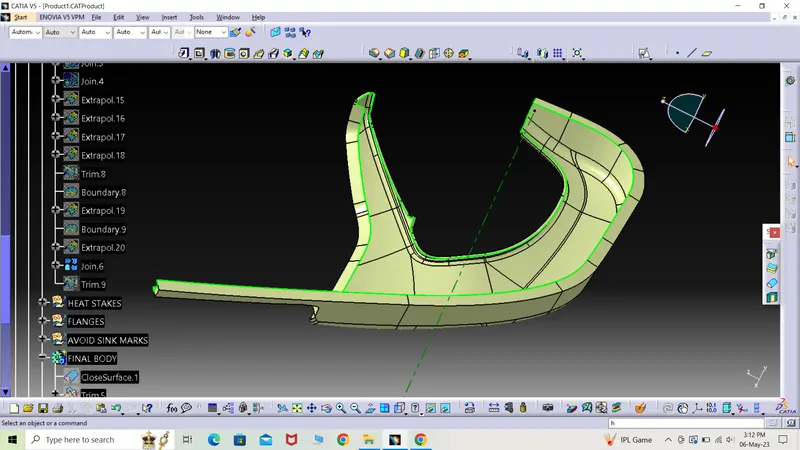
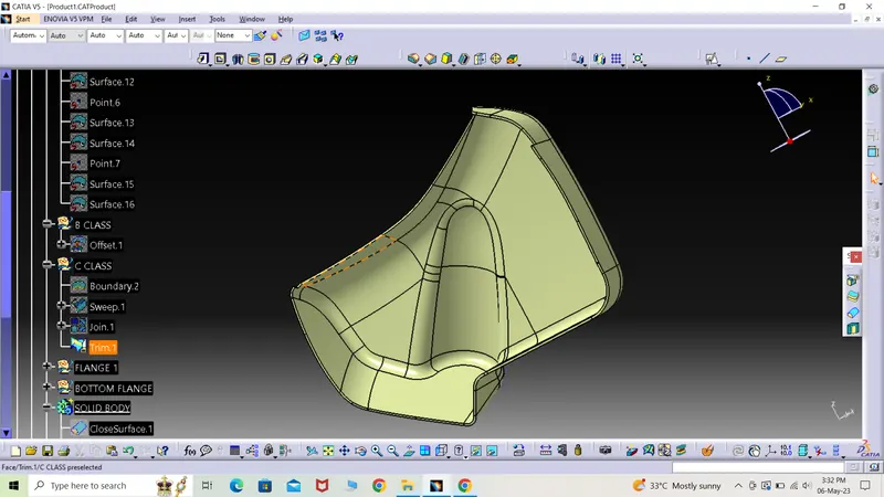
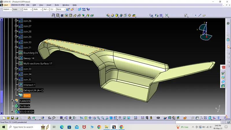
*) Class A+C was then checked for well intersection region with class B and after several extrapolation, these two surfaces were trimmed to form a complete hollow lower substrate.
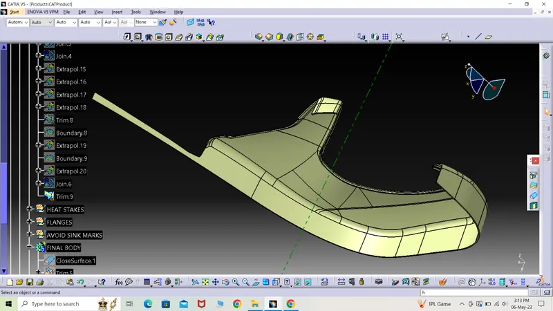
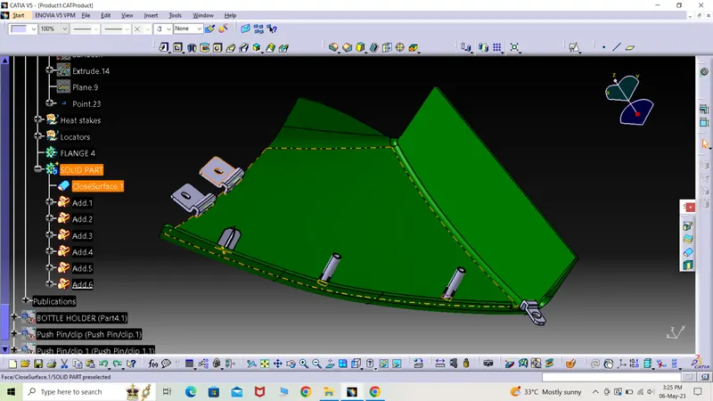
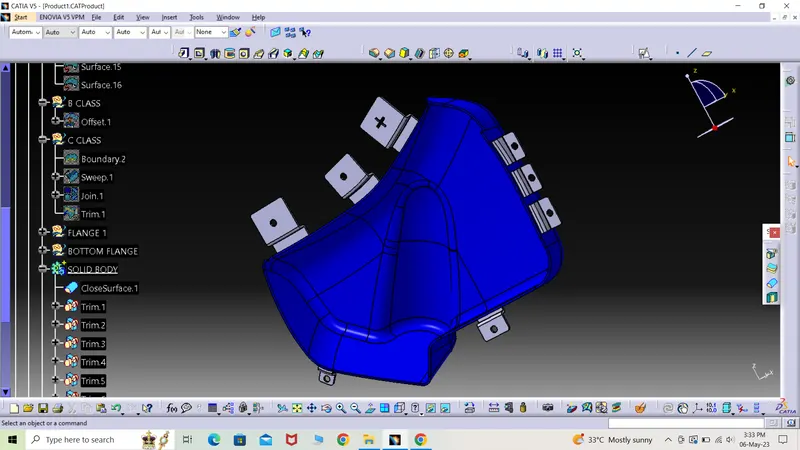
*) The same hollow part was converted into a solid part by using close surface command in the part design mode to obtain the final lower substrate.
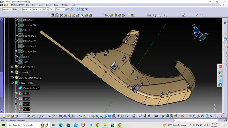
*) The same technique was used to create the other parts.
MAP POCKET
Class A surface
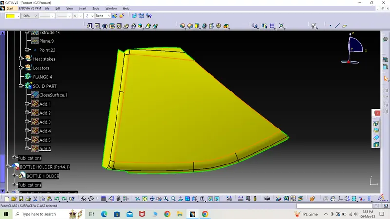
Draft analysis of class A surface
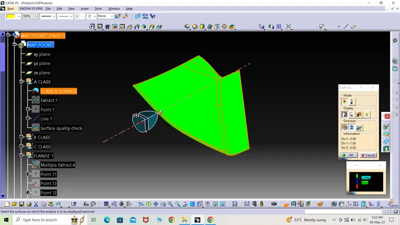
*) The surface is absoulutely OK and passes the draft analysis with value 2.9 degrees.
B Class surface
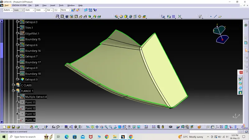
C Class surface
BOTTLE HOLDER
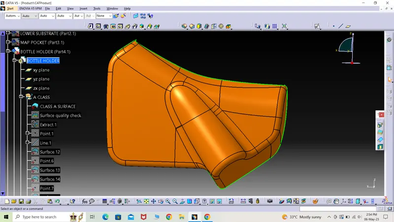
Class A surface
Draft analysis of class A surface
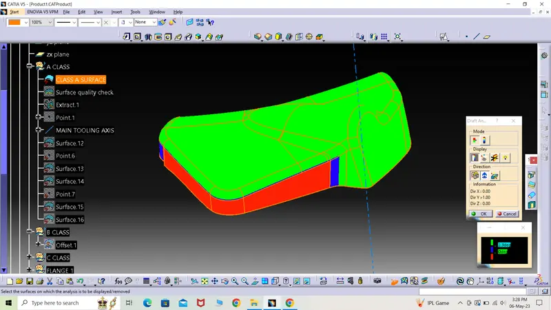
*) It was found that there were some regions which failed the draft analysis and a report has to be prepared by the design engineer to seek permission to modify the same surface and also to intimate the class A sketcher about the fault in the same region.
B Class surface
C Class surface
ARM REST
Class A surface
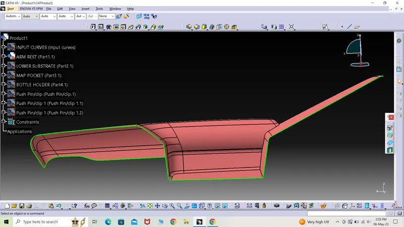
*) Surface was not a good one.
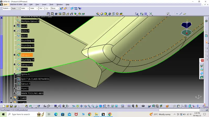
*) It was modified by using extract, line, spline, split, extrapolate options and finally repaired th surface.
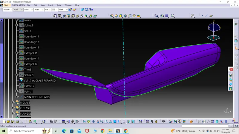
Draft analysis on repaired class A surface
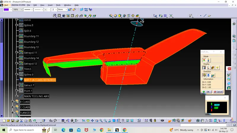
*) It was found that there were some regions which failed the draft analysis and a report has to be prepared by the design engineer to seek permission to modify the same surface and also to intimate the class A sketcher about the fault in the same region.
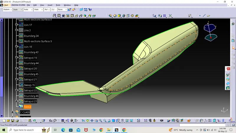
Class B surface
Class C surface
Hollow complete part
Solid complete part
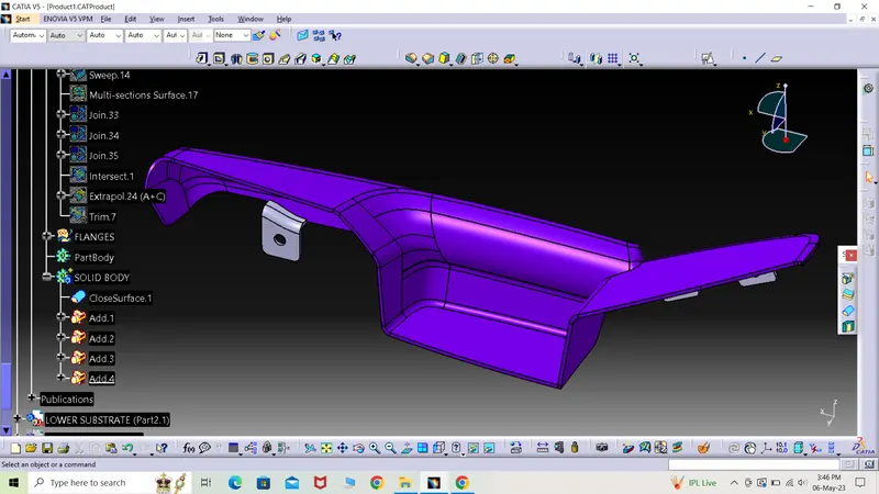
*) Push clip was already given which later was assembled and is explained below.
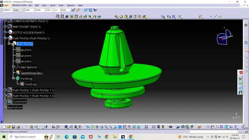
*) To connect or fix these parts together, there are locators, heat stakes and screw boss given to substrate and flanges to the other components.
Heat stake creation
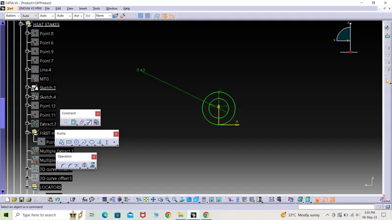
*) A plane was created using the master section. The same points were then isolated to break any link with the master section.
*) The same plane was then used to create the sketch of the circles with radius 7.5 and 4.7mm.
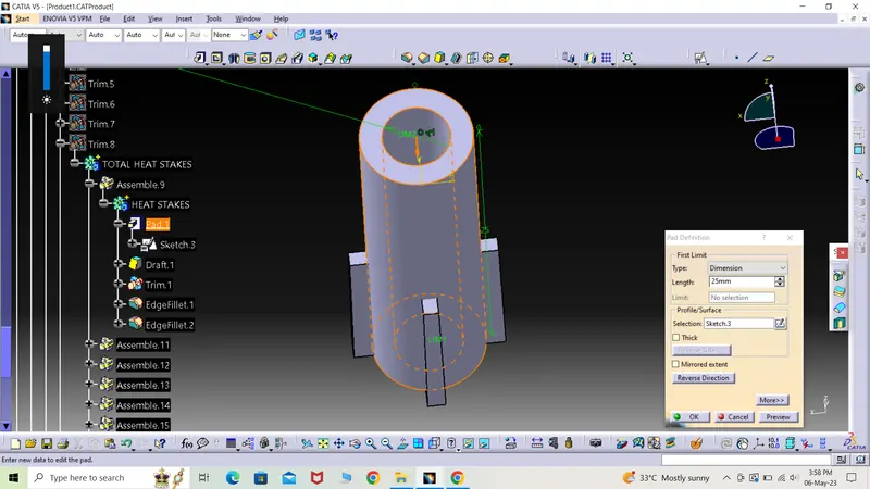
*) The sketch was padded and drafted to 25mm and 0.5degree respect inside and outside.
*) The sharp edges were filleted with 0.25mm.
Locators
*) A plane was created using the master section. The same points were then isolated to break any link with the master section.
*) The sketch was padded and drafted to 25mm and 0.5degree respect inside and outside.
*) The sharp edges were filleted with 0.25mm.
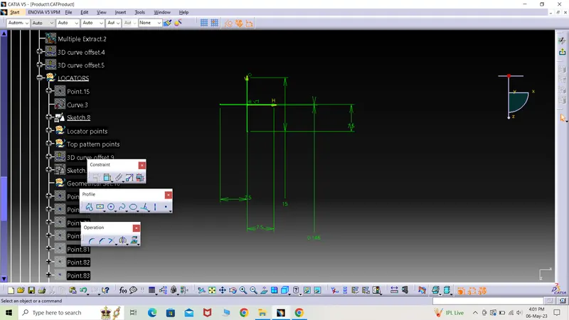
*) The top edges were chamfered to 3mm 45 degree to get the perfect locator design.
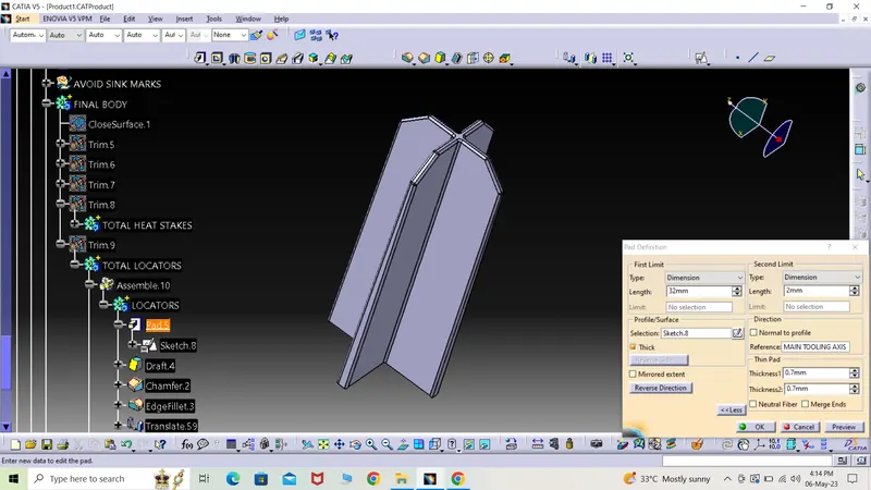
*) Several points were created to fix the location of the locators, heat stakes.
*) Each was copied and paste special with link and then translated with point to point option.

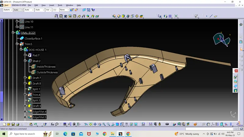
Dog house creation
*) A plane was created using the master section. The same points were then isolated to break any link with the master section.
*) The sketch was padded and drafted to 25mm and 0.5degree respect inside and outside.
*) The sharp edges were filleted with 0.25mm.
*) Side core axis was created taking the perpendicular side as reference. A line was created using point to point option.
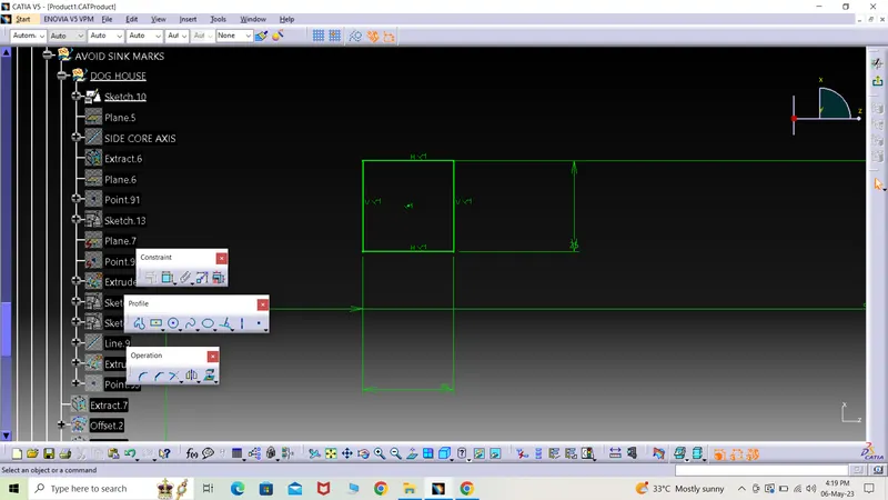
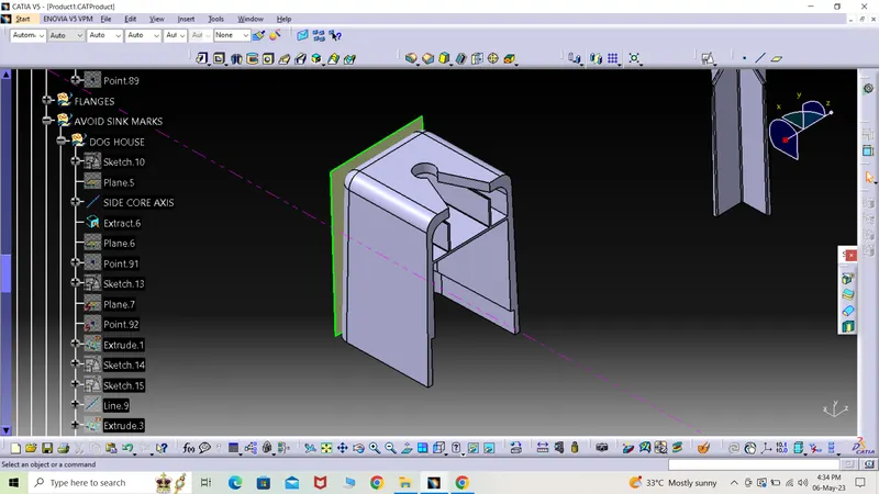
*) Inner pattern was also sketched and padded using the side core tooling axis.
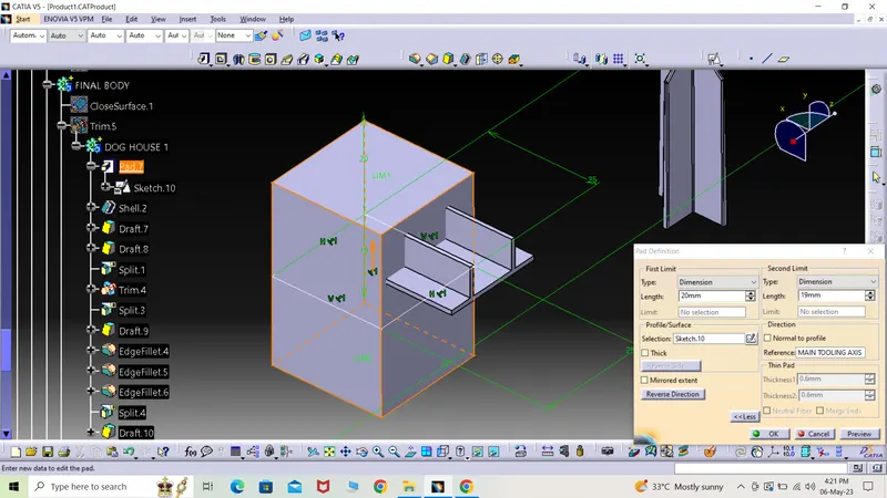
*) The inner portion was shelled.
*) Outer region was drafted taking main tooling axis reference.
*) The top hole pattern was created in the same manner. A sketch was created and later extruded. The portion was later splited with the main dog house body in part design mode.
*) The edges were filleted with 3mm and 0.25mm.
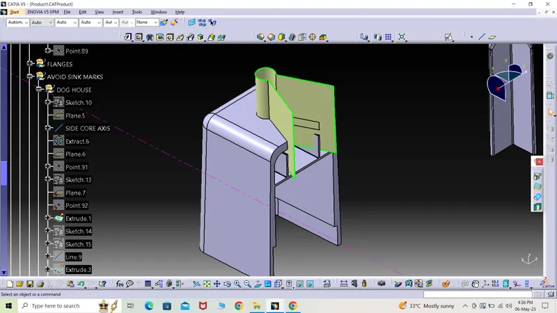
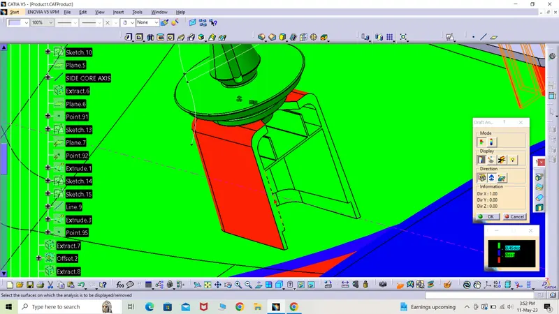
*) Draft analysis on the dog house was carried out.
*) The side core axis was used with draft angle 0.5 degree.
*) The outer surface was tested with 2.9 degree draft.
*) Two more were created by simply creating points on the desired location and then copied special and translated to those points.
*) It was kept in mind that the distance between any two engineering feature was more than 50mm.
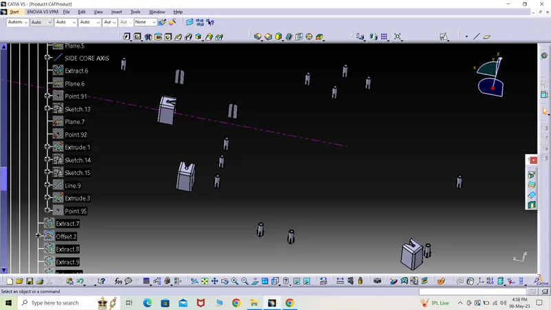
*) All these enginnering features were later added to the main body by boolean operation.
*) A new feature i.e. flange was given to the parts by referring the master section.
*) A plane was created and then top pattern was created.
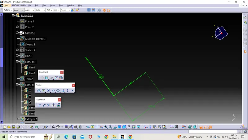
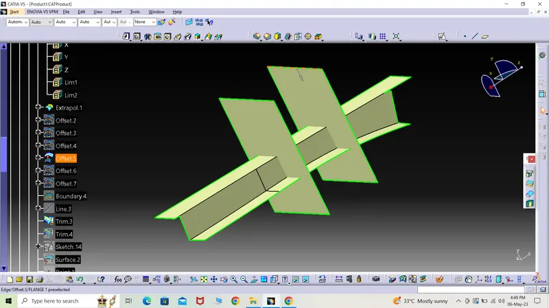
*) The base was separately created and was trimmed. Vertical extruded lines were used to cut the portion to exact length of the flange.
*) The surface was thickened and then splitted with the same extruded surfaces.
*) A separate hole was created by the same technique to allow the heat stake to slip into the flange for locking purpose.
*) For locators, the sketch was created as per the locator and then created in the same manner.
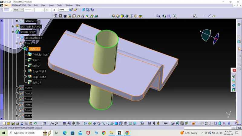
*) Sharp edges were filleted with value 3mm and 0.5mm.
*) Flange was completed.
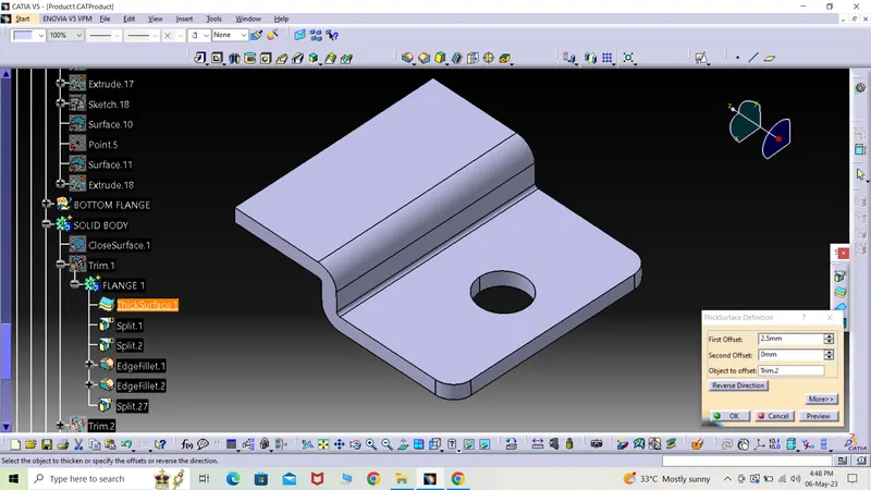
*) Locators flange hole was created by a sketch, extrude and then trim the solid part to get the desired flange.
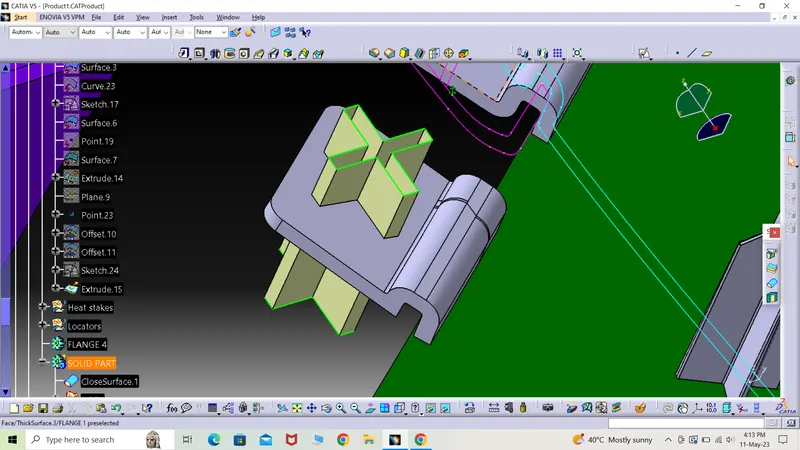
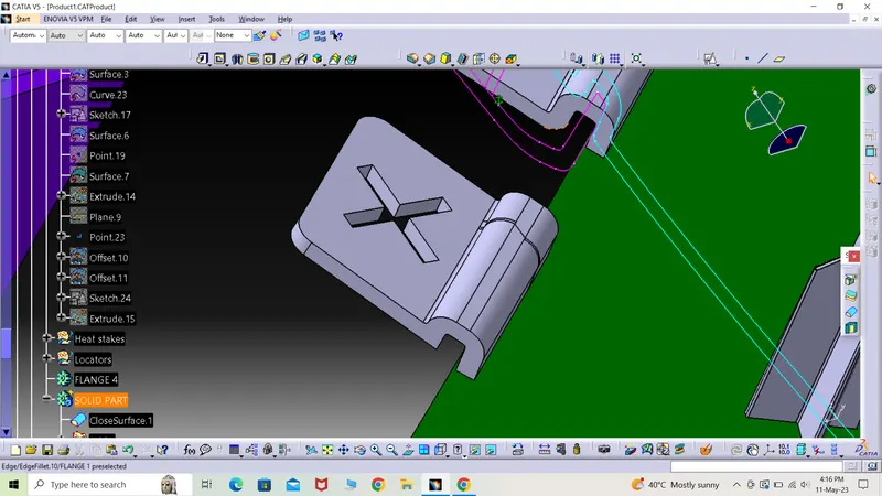
*) In the same manner, all the other flanges were created according to the location of the locators and heat stakes.
*) In the same manner all the other parts were also completed with the engineering features wherever necessary.
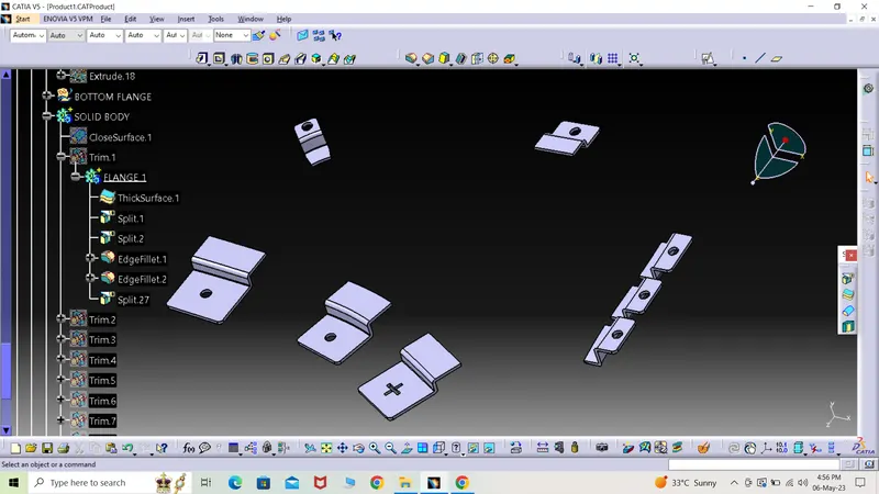
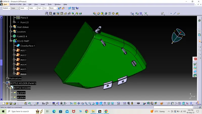
All the finished parts are shown below:-
Bottle holder
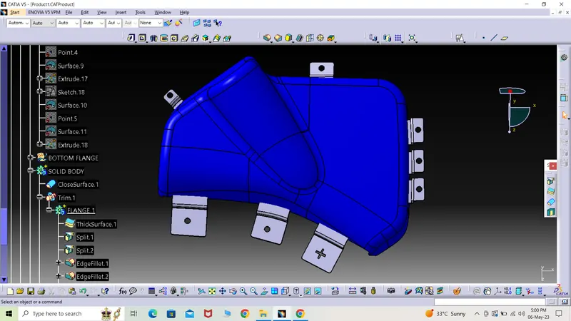
*) Draft analysis of bottle holder is shown below with 3 degree draft. The result shows some regions with red color patches which means that particular portion failed in the draft analysis. To correct the same region, a report has to be prepared and given to the class A surface developer where he would either recreate the surface or allow us to make changes on the class A surface.
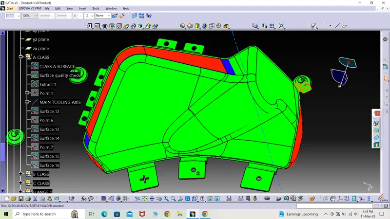
MAP POCKET
*) Draft analysis of map pocket is shown below with 3 degree draft.
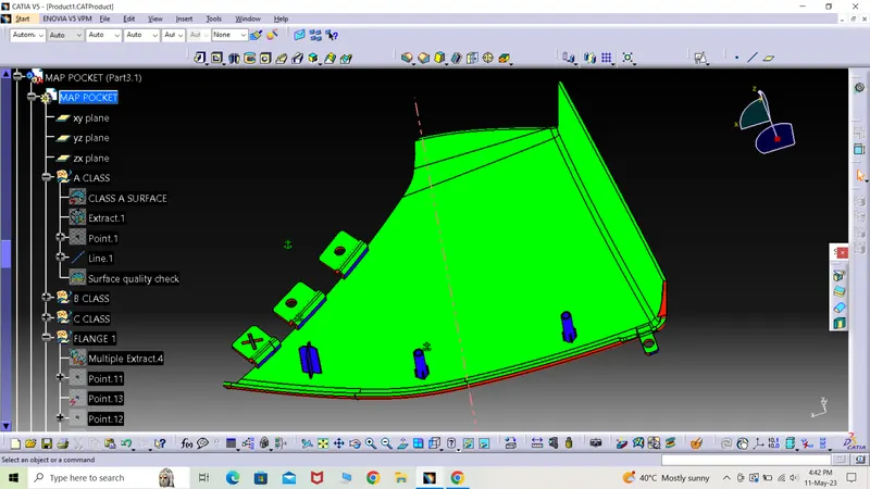
LOWER SUBSTRATE
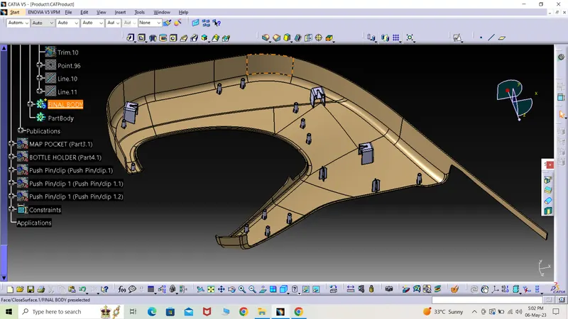
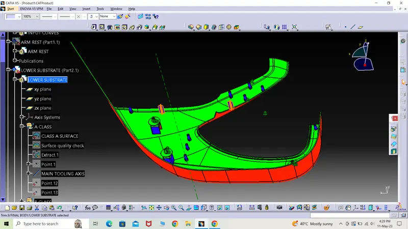
*) Draft analysis of lower substrate is shown below with 3 degree draft.
ARM REST
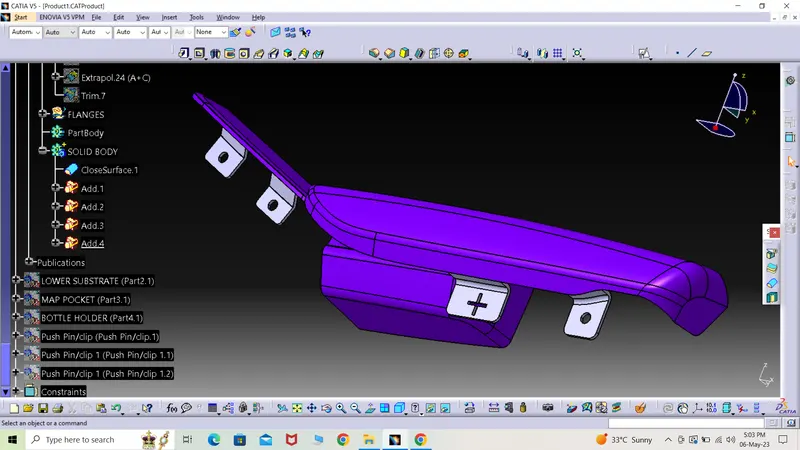
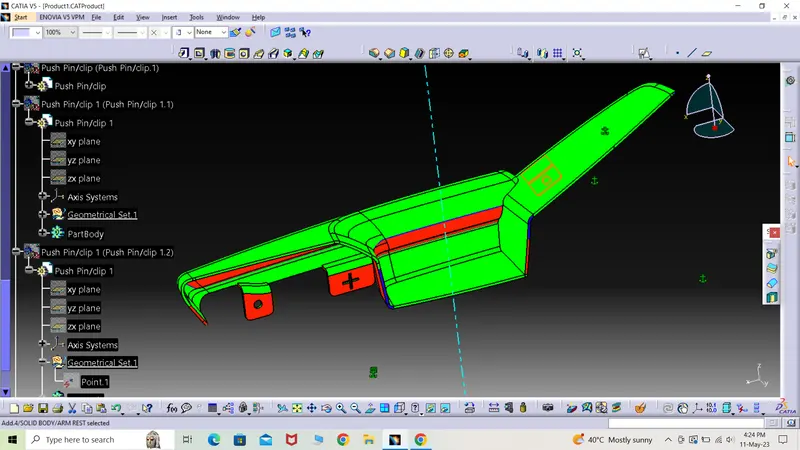
*) Draft analysis of arm rest is shown below with 3 degree draft.
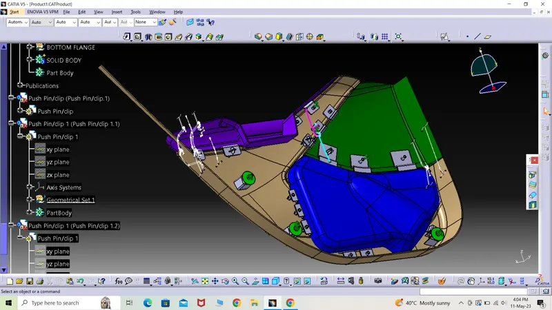
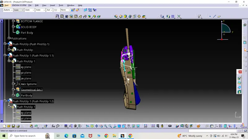
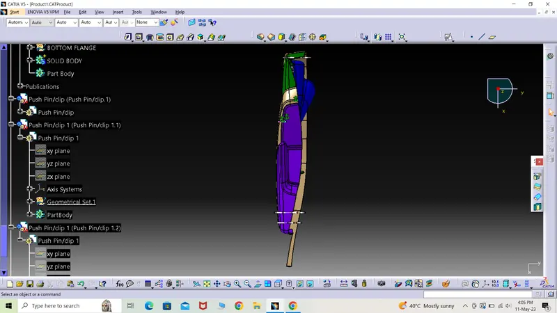
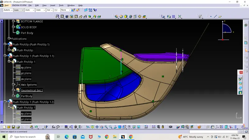
*) Complete door trim is shown below in various views
ISOMETRIC VIEW
FRONT VIEW
TOP VIEW
SIDE VIEW
*) The whole part was applied with gold material and is shown below