Week -2
1)Simlulation of a door bell.
A door bell consists of a battery,solenoid,switch,plunger, and a metal gong.
*)Battery-It is made of various cells that stores the current and supplies the same when the circuit is complete.
*)Solenoid- It is electromagnetic device which behaves like a magnet on passing the current to it. It is a cylinder made of metal on which a copper wire is wounded to form a coil. The winding is densed in order to get more current. This is connected to a current supply like a battery.When the battery supplies the current through the coil.The metal cylinder gets induced by magnetism which makes it behave like a magnet. Technically, this is nothing but electromagnetism which is the production of magnetism on passing current through a conductor.This can be observed by putting some metal nails near to the solenoid.On passing the current,the nails would stick to the solenoid and the nails fall apart when the current is turned off.
*)Switch is a electrical device used to on/off a circuit. It allows or breaks the flow of current on pressing.
*)Plunger is a metal arm which is connected with a spring or motor in some cases.The plunger moves to and fro according the power supply.
*)Metal gong is metal round semi sphere like disc on which the plungers strikes.The kinetic energy of the plunger gets converted into sound and heat energy and this is why gong is responsible for the sound that gets produced in the house.
*)When a person presses the button situated near the door area,the bell inside the house rings.Pressing the switch supplies the current to the battery.The battery energies the solenoid.The solenoid working on the principle of electomagnetism attracts the plunger arm which moves it at the gong side. This strikes the gong.But,in this manner it also breaks the circuit which forces the plunger to return to its orginal position done by the springs.This again completes the circuit and again the solenoid gets energized and the plunger strikes the gong again.This cycle is repeated till the time,the switch is pressed and stops as soon as the button is released. This energizing and deenergizing is so quick that it makes the gong produce a continous sound.
Simulation model of a doorbell
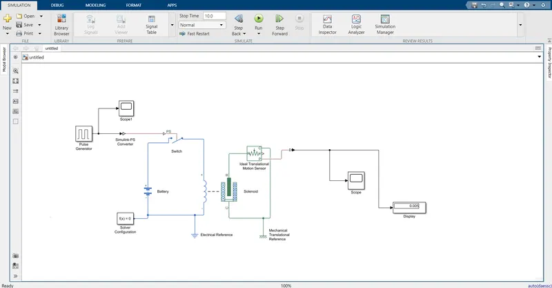
The blocks used are:-
Pulse generator - It is used to generate the input signal which is kind of pressing the switch.The changes I have made according to the given data in the question.
*)Amplitude is the height of the crest in the output graph which is set to '1'.
*)Period is the time span of one whole cycle which gets repeated every time.Period is set to '4' secs.This means that I have covered the span where the bell the plunger strikes ringing the bell and later moving away from the gong to stop ringing which takes a on and off condition and both gets covered in this 4 sec period.
*)Pulse width is the duration of one pulse which is for how long the pulse remained in that position.It is set to '50' as we want out of those 4 secs I want 2 secs to ring the bell and the other 2 secs to stop it.
*)Phase delay - When two waves are formed in such a way that they are identical to each other but the only difference observed is the time difference in between the two then it is called a phase delay. It is kind of a lag between the timing of two identical waves.I have set it to '2' secs.
Now,I have connected a 'simulink-Ps' block as pulse generator is a signal input and the switch that I have connected is a physical signal.Later,a switch is connected which will be turned on/off depending on the input signal by pulse generator.I have connected the switch with a solenoid on one end and to a battery on the other end. The battery will energize the solenoid depending on the switch inputs.To detect the output sof the solenoid,I have connected a ideal translational motion sensor which will detect the motion of the solenoid and send it further.Here the section consisting of solenoid and battery is grounded by electrical reference just like we Earth the whole electrical supply in our domestic usage. In the same manner in Simulink, there are several types of grounding required to stabilize the whole circuit block.So ideal translational motion sensor section is connected with a mechanical reference.A solver configuration is connected in order to calculate all the equations and find the values which forms the input parameters for the model before simulation.To get the output,I have again changed the physical signal to simulink signals by using Ps-simulink block.The block diagram is concluded by connecting a scope which gives me the output graph shown below.Dispay block displays the output in form of a numeral value.
Output graphs
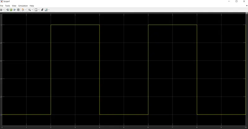
*)Below is the graph of pulse generator which shows that for 2 sec the current given is 0 and then the current send is 1.Here 0 means off and 1 means on like in boolean algerbra it is observed.
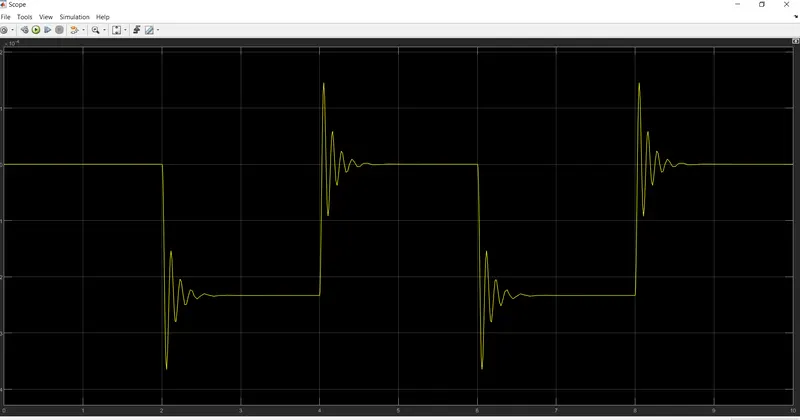
*)Below is the the final output graph of the damper of the plunger which shows when it is away from the gong,there is no pulsation in the graph but after 2 secs the plunger hits and it damps for a short time and does just go to rest immediately after the plunger hits the gong due to inertia.In physics,1st law of motion supports that if a body has some certain mass then it will also have some inertia which will make it to stop after a certain time depending on the mass of the body.Coming back to the graph,the current is off and the plunger returns back to it's original position where again it will take time to come to rest by the same aforementioned law.
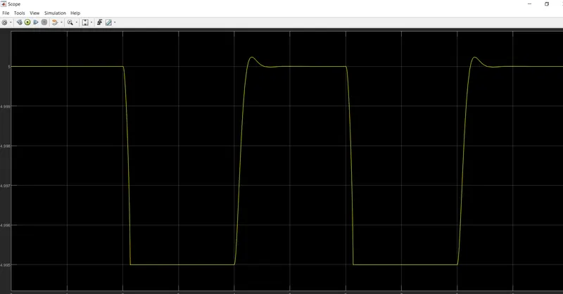
This above graph is another representation of the plunger distance from the gong with respect to time.Initially,it is 5 mm away from the gong for 2 secs then in 2-4 secs it comes near to the gong from 5 -0 mm and stays there for 2 secs.4-6 secs when the circuit breaks, plunger again returns to its original place 5 mm from the gong and the cycle repeats in a similar fashion.The curve on the top of the graph shows the inertia of the plunger which makes it go little more beyond the 5mm mark but it returns back to 5mm shortly.
2)Thermistor
A thermistor is a electrical device which increases its resistance with respect to increase in the temperature.It is very usefull in all automobile,appliances etc where change in temperature is involved which may change the output of that device used.
In this problem, I have to simulate a model consisiting of a thermistor which on detection in change in temperature would either turn on or off the fan mounted in the end of the device.Basically,if the temperature reached a certain degree the fan would turn on automatically by the thermistor or else remain in the off state.
The simulation model is as follows:-
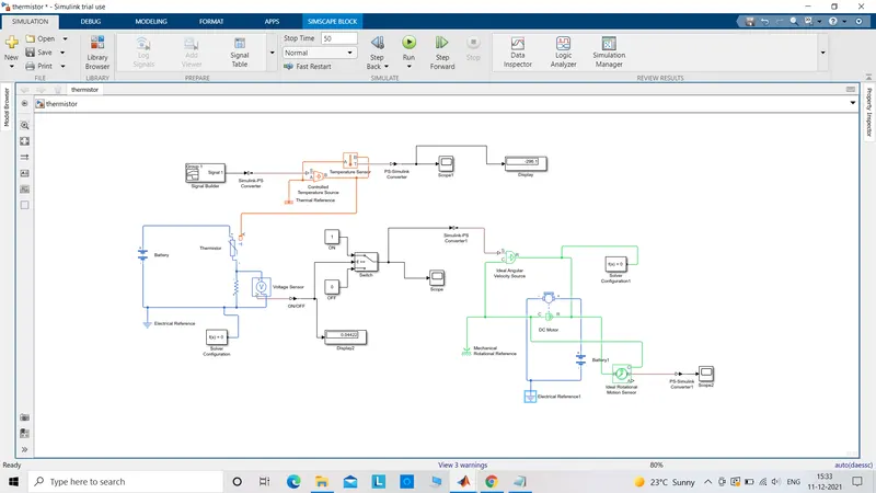
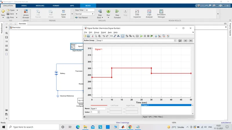
*)Signal builder is used as input here because I have to vary the value of temperature with time.
*)Controlled temperature source(CTS) is connected later with signal builder via a simulink-ps block to convert the simulink signal to physical signals and this is fed to the temperature source which is a energy source to drive the thermistor.To detect the energy from CTS, a temperature sensor is connected with it and it can be graphed by using a scope.This section needs to be Earthed and this is done by using a thermal reference.
*)The output of the above system is then fed to a thermistor.Thermistor connection has to be completed by connecting a battery and a resistor.The output of the thermistor is detected by voltage sensor.This is connected to a display to find the value of the voltage output which is required to set the theshold value in the switch. The value displayed is 0.04422.
*)The switch is pre-configured such that an input of 1 would complete the circuit and allow the current to pass to the motor or if 0 is send as input then the circuit would break and there is no current flow to drive the motor. The value 0.04422 is set as threshold value to run the model correctly.
Graph
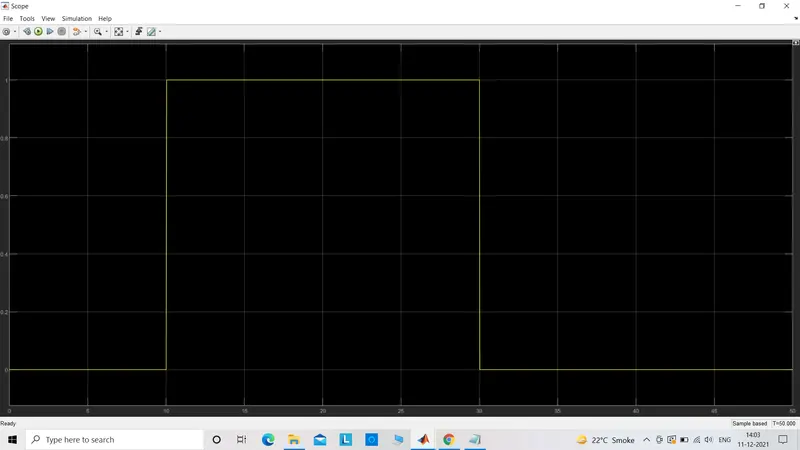
The graph shows that for 10 secs the temperature is less than 25degrees so the fan is in OFF condition and no rise in the graph is observed.For 10-30 secs,the temperature rises above 25degrees so the fan turns ON and the graph shows the rise.For the last 30-50 secs the temperature again goes below 25degrees so the fan again turns OFF.
Hence both the questions satisfy the condition and the models simulate both perfectly.
THANKYOU!