Week - 4
1)Washing machine
?)What is a washing machine and the components?
-Washing(w/m) machine(m/c) basically is a machine that is used to wash out the dirt and stain out of the clothes by supplying soap water to it.
The components are 1) drum, 2) motor, 3) balancer, 4) body 5)console 6) water pump, 7) drain hose and inlet valve, 8) Agitator.
1)Drum- The drum is hollow cylinder which has enough room to store a specific amount of clothes and the drum is that component where all the washing is done. Drum consists of an agitator.
2)Motor- The power supplied to the machine drives the motor which is connected to the drum and spins it.
3)Balancer- A balancer is only there in the machine which plays a role of balancing the drum while it spins.So it is a counter part which avoids shaking of the drum while spinning.
4)Body- The aluminium body fame is designed to look stylish and all the mechanical parts mentions are inside it.
5)Console- It is a set of display,switches and knobs which play a handy role in controlling the way the machine should perform.
6)Water pump- It is used to supply the soap water into the drum.
7)Drain hose- Drain hose removes the dirty water out of the machine.
8)Agitator- It helps to stir the soap water inside the drum.
The processes that occur inside the W/m
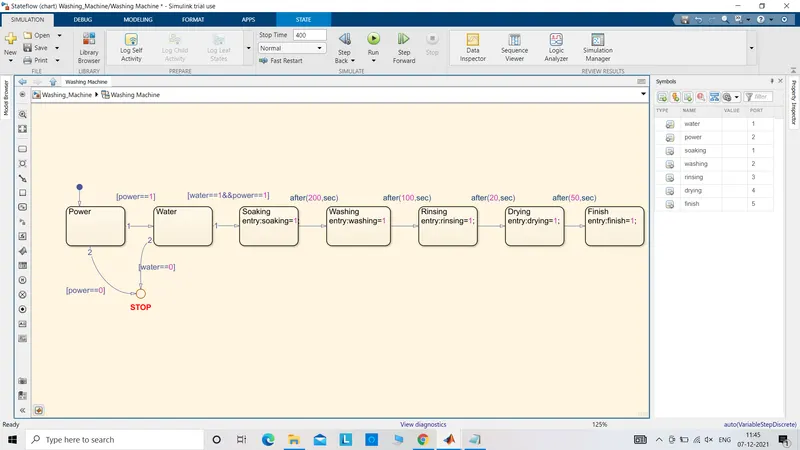
Soaking - Soaking is the process in which the clothes are mixed with the soap and water together to form a single solution.
Washing- Washing is the process in which the clothes are shaken or any type of a circular motion is given to the system which due to friction and heat will remove the dirt out of the clothes getting washed.
Rinse- Post washing,the soap present in the clothes is removed by supplying clean water.
Drying- It is the process of removing the wetness or in other words ,water present inside the clothes by spinning the drum without supplying any supply or water.The spinning causes heat and some amount of water is removed just by centrifugal force which throws the water tangentially outwards and some is evaporated by the heat.
The stateflow model is as follows:-
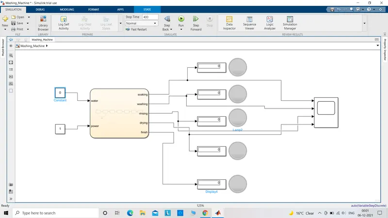
*)The input is a slider switch which when turned on supplied the current to the machine.
*)Water is manually supplied so by changing the value to 1 or 0, the supply is permitted or prohibited.
*)The chart is the main block of the state flow because it consists full prepared process.
*)The chart is set with power and water as input.
*)All the processes are set to be the output of the chart and all are indicated by the indicating lamp which light up accordingly.
*) The output could be observed on the display and scope.
The simulink model is shown below-
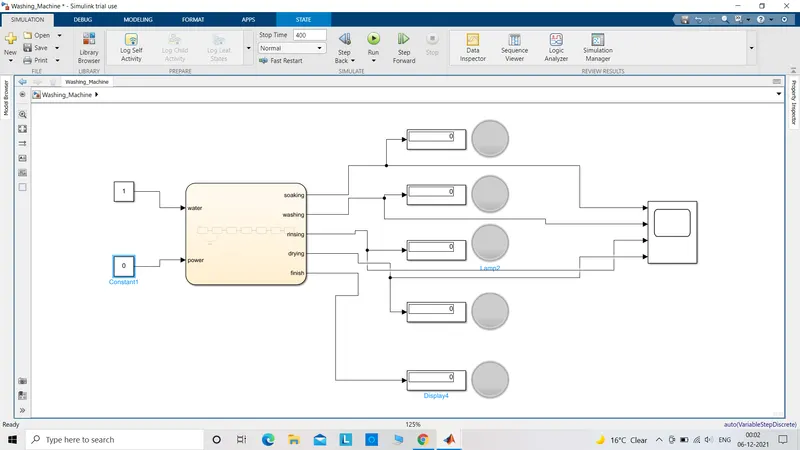
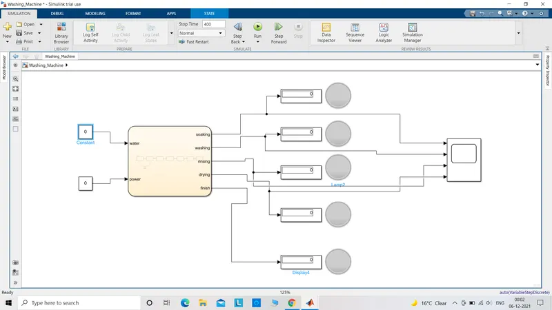
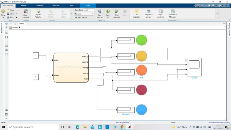
*)When either of the two i.e. power or water ot both are turned off , no indicator turns on which means that the machine does not operate.
*) The machine starts working as both the inputs are given which can be observed as the lights turn on.
*)When all the processes are completed,the blue(in this case) lamp flashes indicating the clothes are ready to be removed from the m/c.
The graph is attached:-
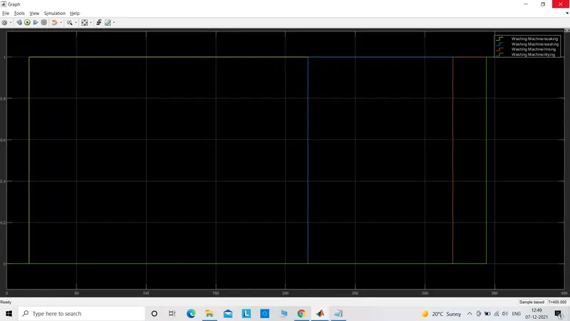
*)The graph shows the beginning of each process with respect tot time when the inputs are provided in form of 0 or 1.
2.Simulate gear system of an automobile
A gear system of an autmobile is a set of gears which is used to produce a better output speed or torque of the vehicle according to the conditions.The shaft of the reciprocating engine is connected to the input shaft of the transmission or gearbox.Gearbox has two sets of shafts with number of gears on each shaft.The gears are of different diameter which is known as gear ratio to give a desired output.The output shaft of the gear box is connected to the axle which drives the wheel.
Why it is required?
The engine without a gearbox will produce a low bandwidth of output speed and torque.If there is only one gear with a specific diameter then it will produce a constant output performance.By fitting several gears with variable diameters, the car with the same engine dimension can produce different performance in each gear.The logic lies in the way different gears with different diameter perform.Suppose,two gear with same diameter are meshed then the output would be the same as the input gear.So if input gear has a rpm range of 0-400rpm then the output would also rotate with range of 0-40rpm.Now,If two gears with different diameters are meshed with smaller input and larger output gear and if the input gear rotates at 500rpm would make the output gear rotate say at 300rpm which means more torque is getting produced.High top speed is gained in the other way round.This is how variable speed adn torque is produced by connecting a gearbox.
The simulink model is as follow:-
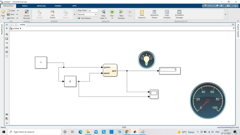
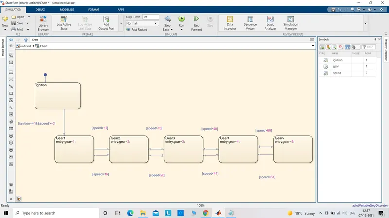
*)The blocks used are constant,slider gain,chart,scope,display,speedometer and a lamp.
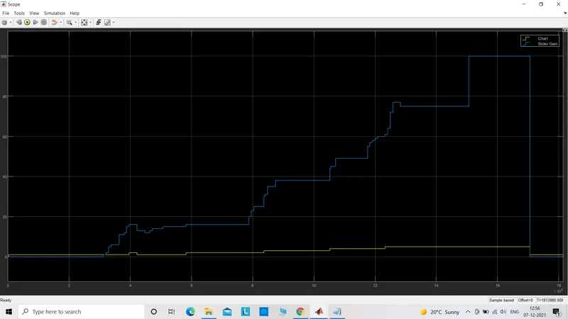
*)Slider gain is chosen as I have to test the model for a variable output under revving the engine at different speeds.When using a slider gain,I used inf as time input so that I could give the input according to my will and the output graph records all the instantaneous values.
*)Lamp is used to indicate that the output is achieved. Here,my car is already in 1st gear as soon as I turn on the ignition. My first upshift happens when I exceed the 15km/h. So,the lamp lights up when the car exceeds 15km/h or else it remains in off condition.
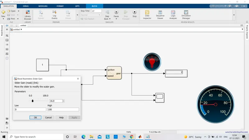
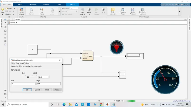
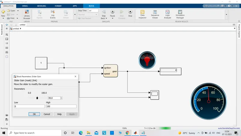
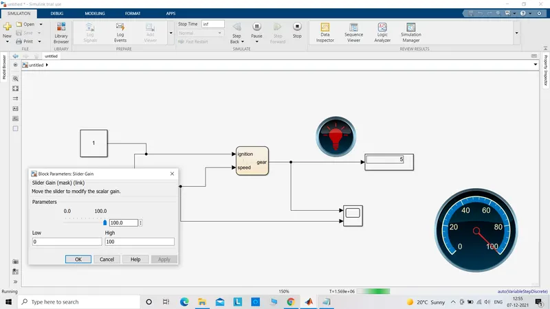
*)Speedometer is connected by using the connect option on the top of that particular block and then clicking on the circuit or block with which it has to be connected.It displays the speed of the vehicle which is 0-100km/h in this case.
The graph shows the speed output and when the gears are changed from 1 to 5 and then back.
The models are simulated and the output are properly attached.Thankyou!!