Week 12- Final project
DEVELOPMENT OF DOOR TRIM PANEL:
OBJECTIVE:
To create a complete door trim panel assembly form the given class A surface as an input along with engineering features as required with design standards using CATIA V5.
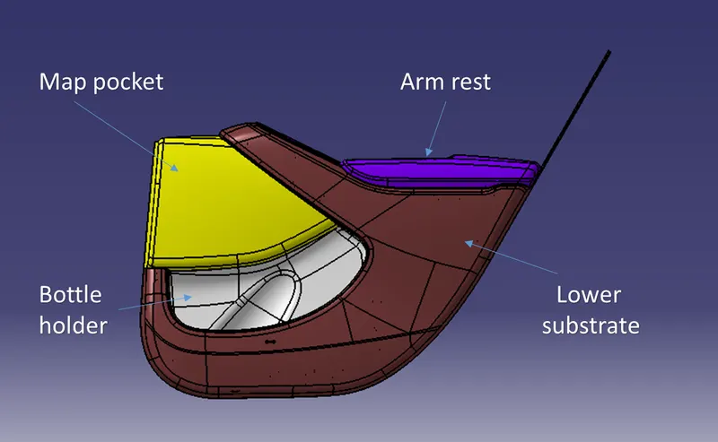
The door trim pannel divided into:
- Door arm rest
- Lower substrate
- Upper map pocket
- Bottle holder
Each parts are developed into a solid plastic parts with engineering features like heat stakes, locators, dog house etc. as required from class A surface. Tooling and draft analysis are checked for mold (core & cavity) movement.
INTRODUCTION:
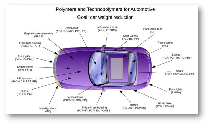
According to a recent study, for every 10% reduction in vehicle weight, it reduces fule usage by 6 to 8%. Due to current environmental and economic concerns, automobile manufacturers are now incorporating more advance plastic materials so as to reduce weight and make the vehicle more fuel efficient.
Advantages that these plastic used in transportation vehicle are:
- Improved safety and comfort
- Fuel efficiency
- Flexibility in integrating components
- Design freedom
- Weight reduction
The most commonly used plastics in automobile industries are:
- Poly-vinyl chloride
- Polypropylene
- Acrylonitrile butadiene styrene
- Polyamide
- Polystyrene
- Polyoxymethylene
- Polycarbonate
- Polyethylene
Different plastics are used based on their properties like less weight, wear resistant, chemical and heat resistant etc.
Injection molding method:
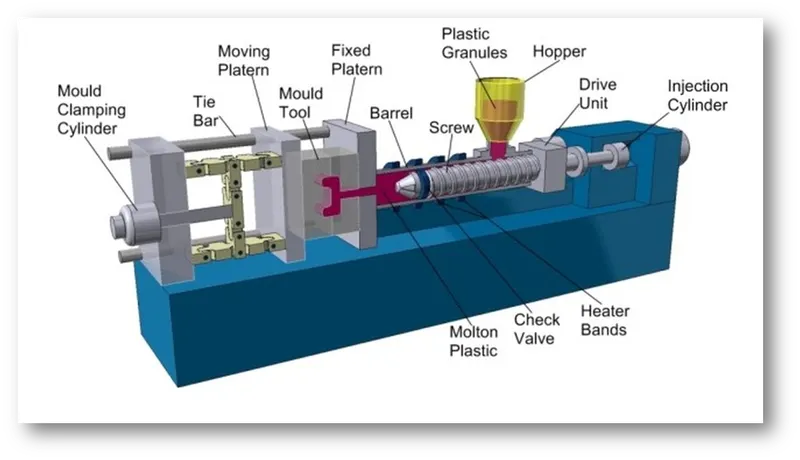
Since plastic plays major role in automobile industry, most of the OEM's, tire 1 & tire 2 companies follow injection molding method. It is a process in which thermoplastic polymers is heated above its melting point, resulting in the conversion of solid polymers into molten fluid with reasonably low viscosity. This melt is mechanically forced that is injected into the mold for the final shape as required.
SEQUENCE OF DESIGN OPERATION:
- Understanding class A surface
- Creating tooling axis
- Draft analysis for class A surface
- Creating class B surface and C surface
- Creating solid plastic part and adding engineering features as required
- Draft analysis for the final solid part
1.) Understanding class A surface:
The class A surface is created by:
- Free hand sketch
- Rendering
- 1:4 clay model
- 1:1 clay model
- Drag force test
- 3D scanning
- Converting to class A surface (software like Alias and others are used)
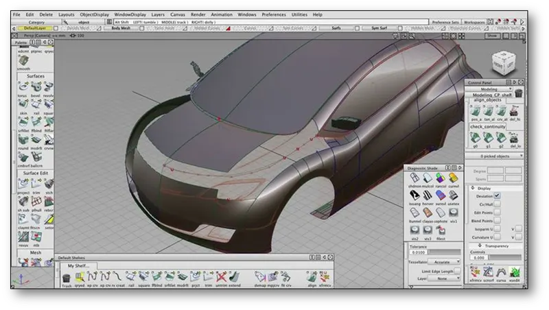
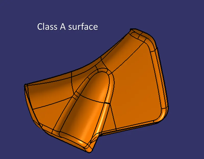
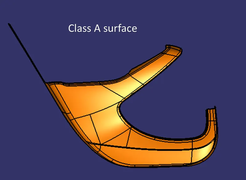
The class A surface is the visible and aesthetic side of the part. It is then developed into solid plastic component with engineering features.
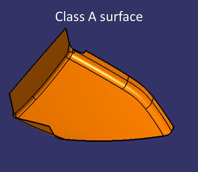
Example of class A surface using alias workbench:
2.) Creating tooling axis:
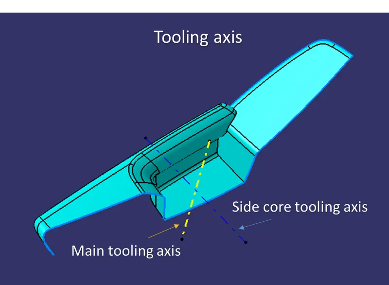
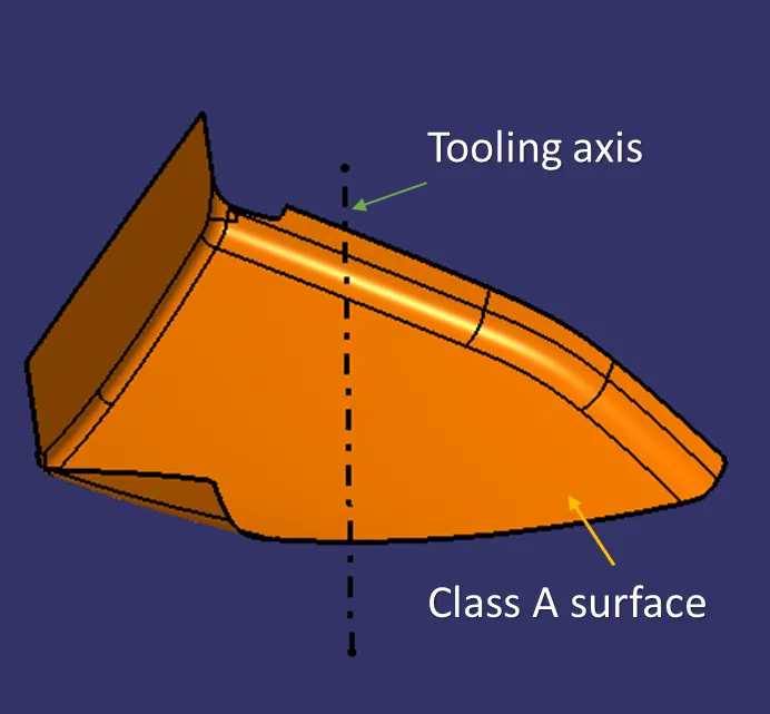
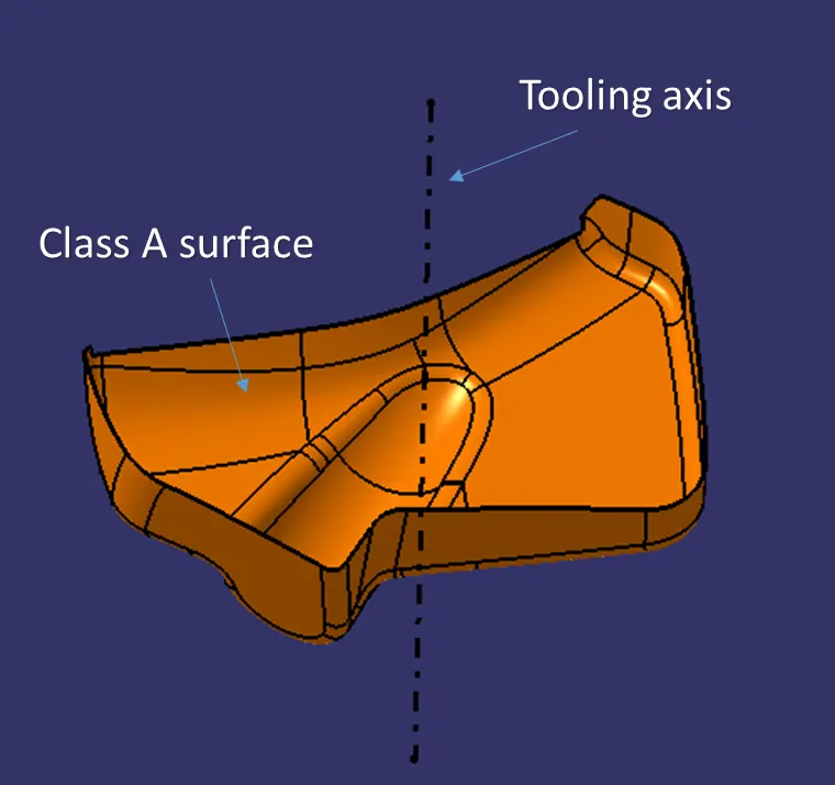
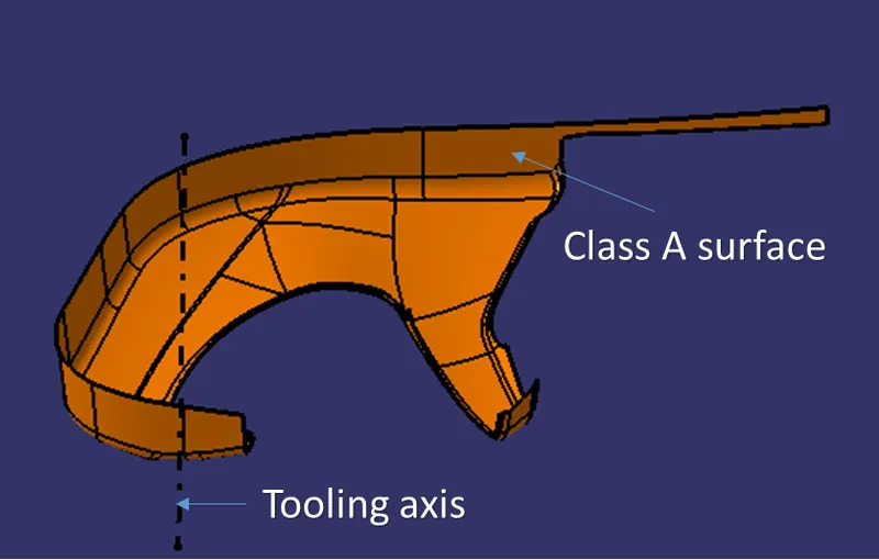
The manufacturing cost per component depends on mold cost, material and cycle time. More complex the part design, more complex and expensive the mold. It also affect the cycle time. The tooling axis plays a major role in mold design. The direction in which the mold (Core & cavity) opens or move is the tooling axis.
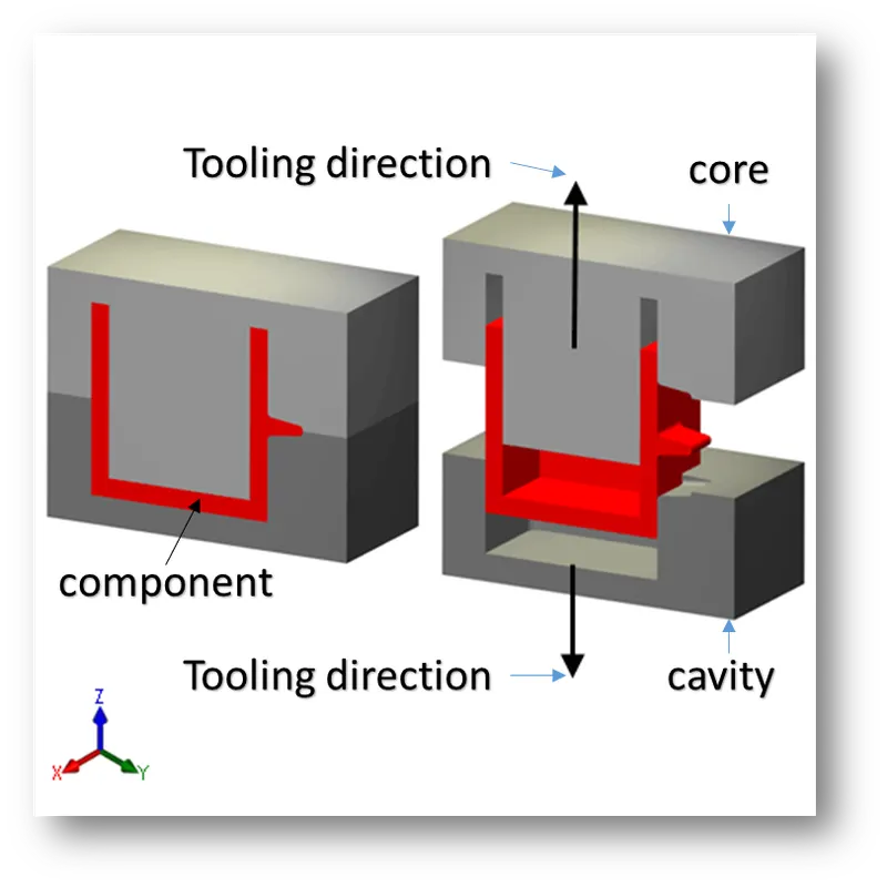
Tooling axis differes from each component. The tooling direction should clear maximum face of a component. Some complicated and unavoidable design requires side core or lifter tooling axis are implimented.
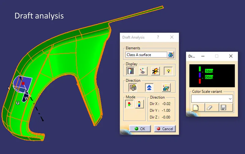
3.) Draft analysis for class A surface:
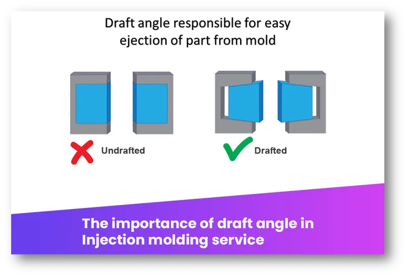
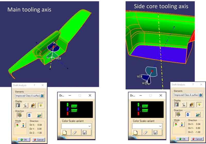
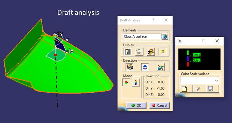
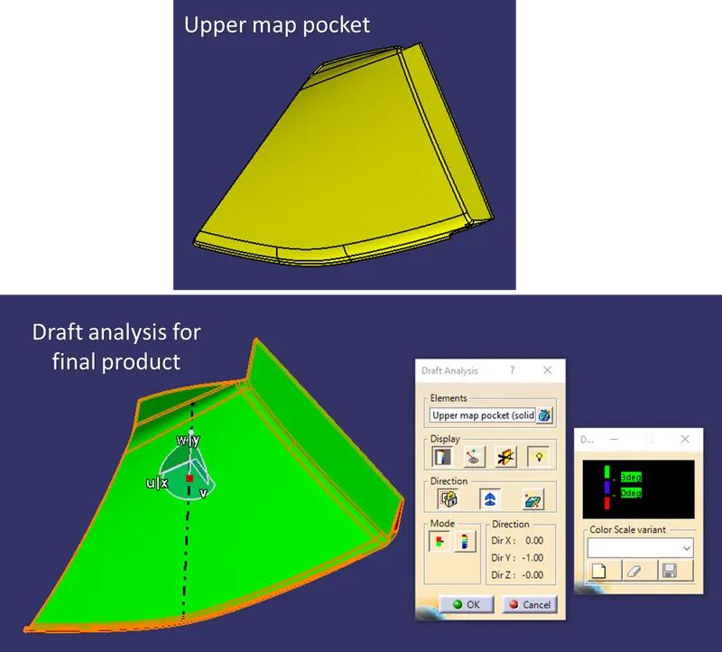
The draft analysis is carried out to ensure the component is clearing the tooling axis. Each component is created with minimum draft value. The draft angle allows the component for ease of ejection from the mold.
The nominal draft angle is 3°.
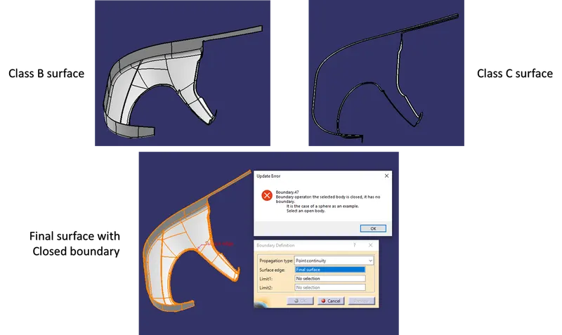
4.) Creating class B and class C surface:
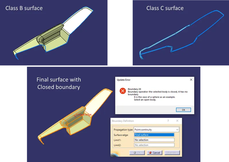
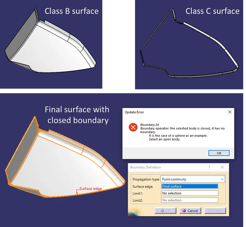
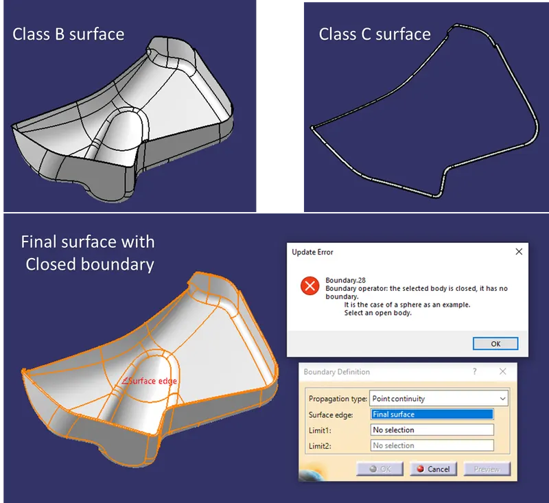
The class B surface is created by offsetting the class A surface with required thickness and checked for surface boundary condition and the minor patches are by using tools like boundary, extrapolate, trim, join.
The class C surface is created from class A surface by using multiple extract, sweep with surfrace, sweep with tooling axis, multisection, trim, join.
The class A and class C are joined together and trimmed with class B surface to form the final surface.
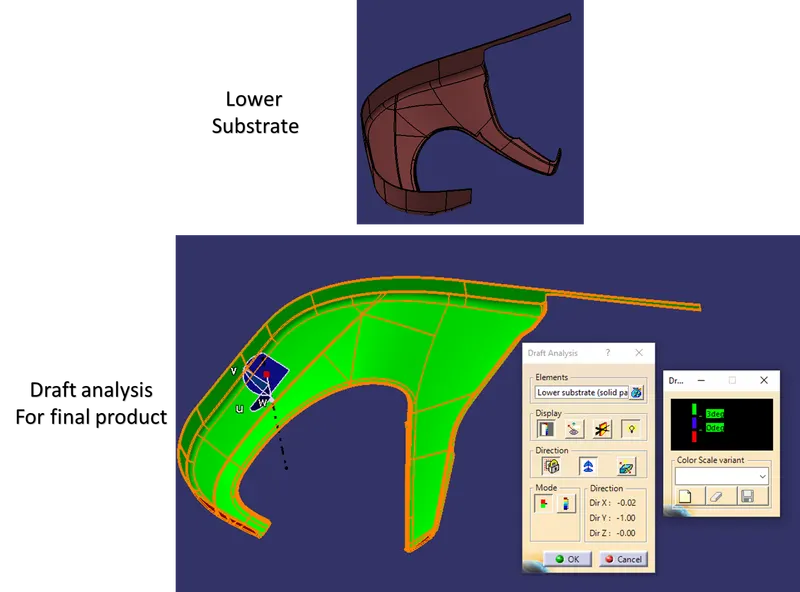
5.) Creating solid part and adding engineering features:
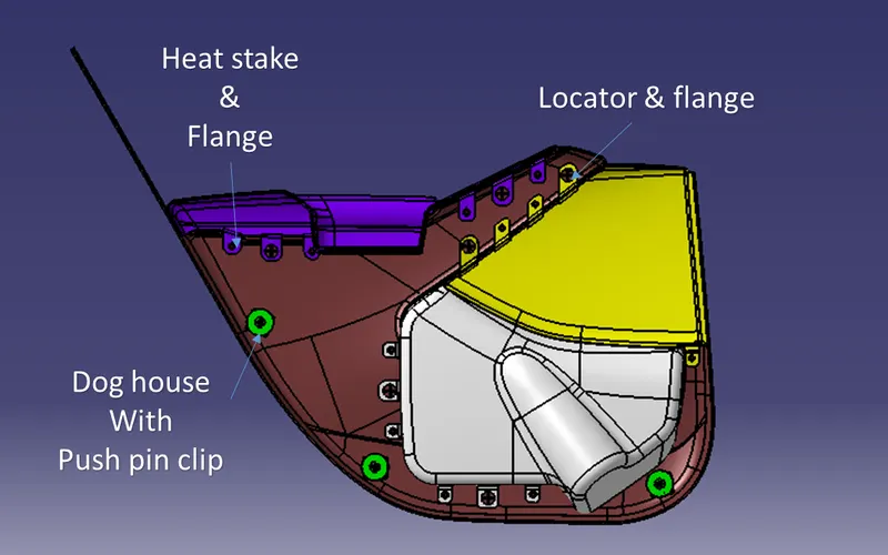
The final surface is converted into a solid part and engineering features like heat stakes, screw boss, 4 way locator, 2 way locator, dog house, ribs, push clips etc are added as required.
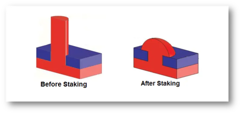
Heat stakes:
It is the process of permanent joint between two dissimilar materials in which one of them is plastic.
Locators:
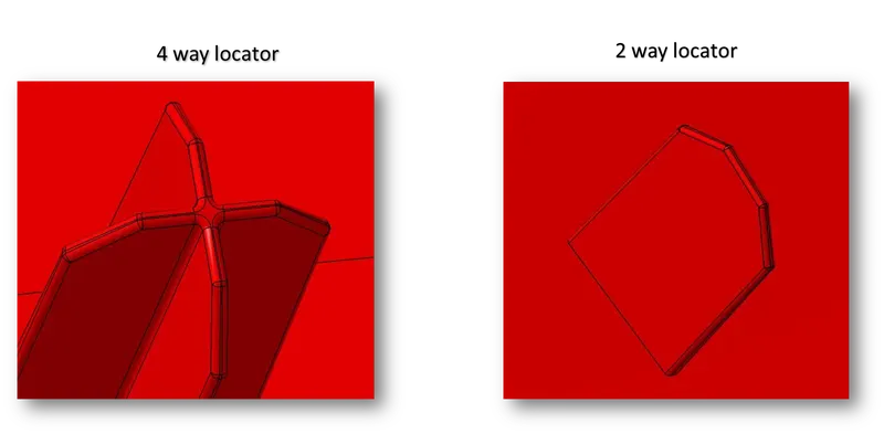
It used to locate the exact position with the mating part.
4-Way locator: Used to arrest motion in 2 axis or four degrees of freedom
2-Way locator: Used to arrest motion in 1 axis or two degrees of freedom
Dog house:
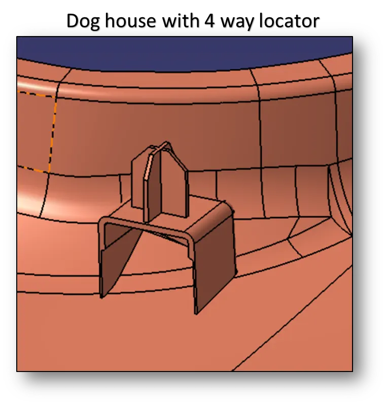
It is used as a supporting features in which locators, push pins, screw boss, heat stakes are mounted.
6.) Draft analysis for final solid part:
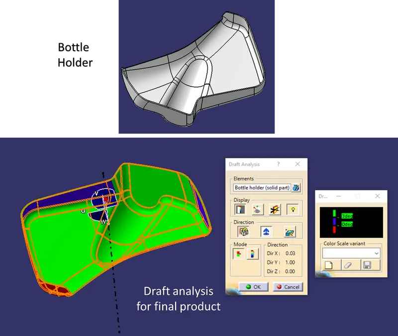
The draft analysis for the final solid plastic part with engineering features on B surface should be done for final results.
RESULTS & REPORT FOR DOOR TRIM PANEL:
1.) Door arm rest:
- Class A surface:
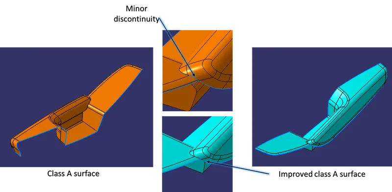
The class A surfae has a minor discontinuity, in industries we must inform to our higher officials. As for project we improved the class A surface.
- Tooling axis:
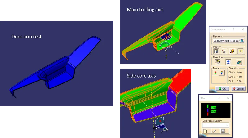
The arm rest requies two tooling axis main and side core tooling axis.
- Draft analysis for class A surface:
The draft analysis clears the tooling direction.
- Creation of class B and class C surface:
- Creating solid part and draft analysis:
The draft analysis results are positive. The blue colour has the draft value of 2.5° which is acceptable.
2.) Upper map pocket:
- Class A surface:
- Tooling axis:
- Draft analysis for class A surface:
From the below result, the draft analysis results are positive and good to go for next stage.
- Creation of class B and class C surface:
- Creating solid part and draft analysis:
3.) Bottle holder:
- Class A surface:
- Tooling axis:
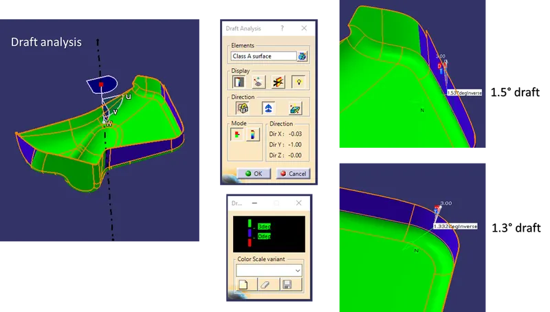
- Draft analysis for class A surface:
The analysis result shows that most of the surface has 3° draft and in few surfaces 1.5°,1.3°, 0.75° draft are observed which are acceptable.
- Creation of class B and C surface:
- Creating solid part and draft analysis:
4.) Lower substrate:
The lower substrate has the engineering features in which door arm rest, map pocket and bottle holder are going to assemble onto it.
- Class A surface:
- Tooling axis:
- Draft analysis for class A surface:
From the below result, the draft analysis are positive and can proceed for next stage.
- Creation of class B and C surface:
- Creating solid part and draft analysis:
5.) Draft analysis for engineering features:
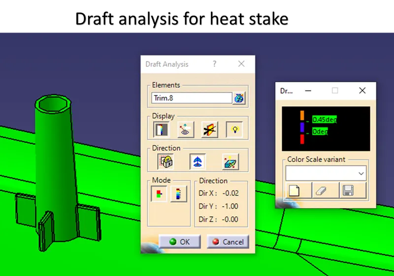
- Heat stake: The heat stakes are designed using the master section.
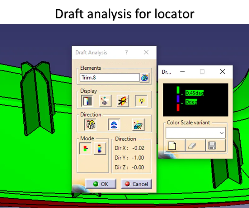
- 4 way locator:
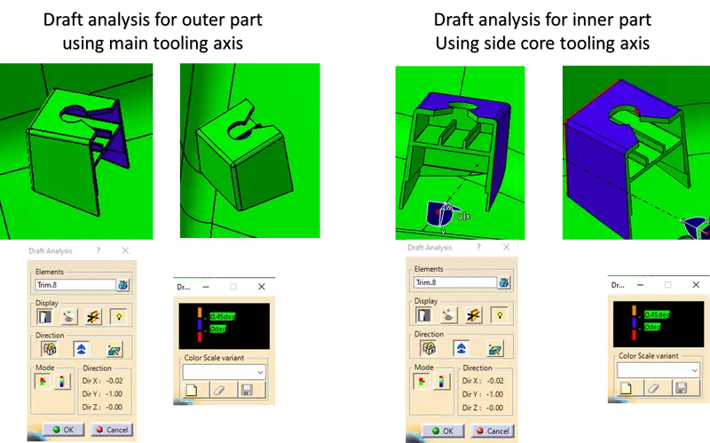
- Dog house:
- Lower substrate:
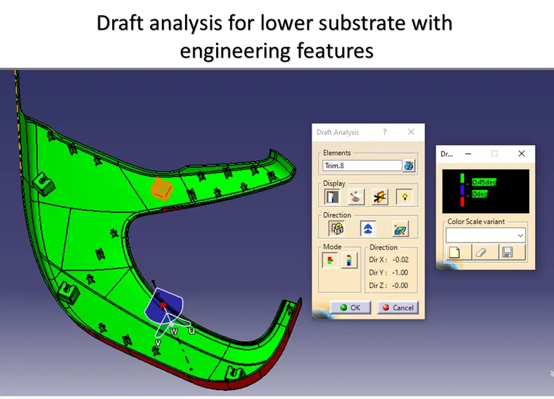
The engineering features are followed with design rules, the above results shows the engineering features are clearing the tooling axis.
FINAL DOOR TRIM ASSEMBLY:
- Left side view:
- Right side view:
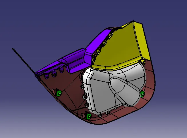
- Isometric view:
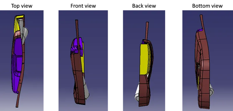
- Other views:
CONCLUSION:
The door trim pannel assembly design has been completed with required engineering features. The results are attached. The CATpart and CATproduct files are attached.