Week 10 - Challenge 1- Attachment Feature Creation (Ribs & Screw Boss)
DOOR HANDLE (RIBS & SCREW BOSS DESIGN)
OBJECTIVE:
To create a door handle component from the given class A sufrace and engineering features like ribs and screw boss features are added to the B surface.
DESIGN PROCEDURE:
- Understanding the class A surface
- Creating tooling axis
- Draft analysis for class A surface
- Creating class B surface
- Creating class C surface
- Draft analysis for final plastic component
- Adding required engineering features to the product (ribs & screw boss)
1.) Understanding the class A surface:
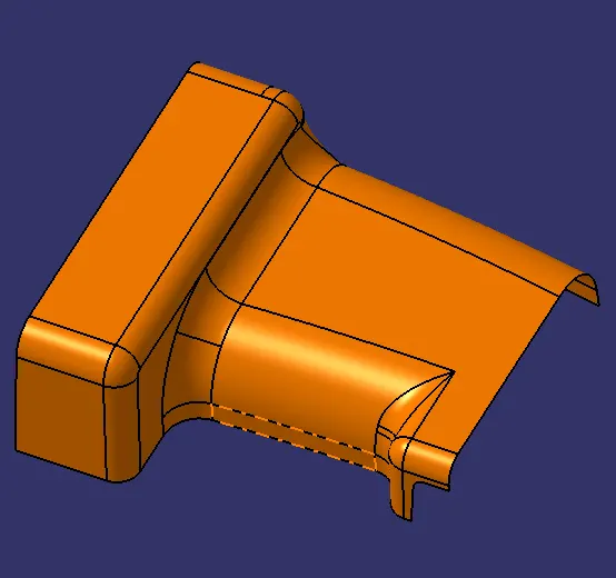
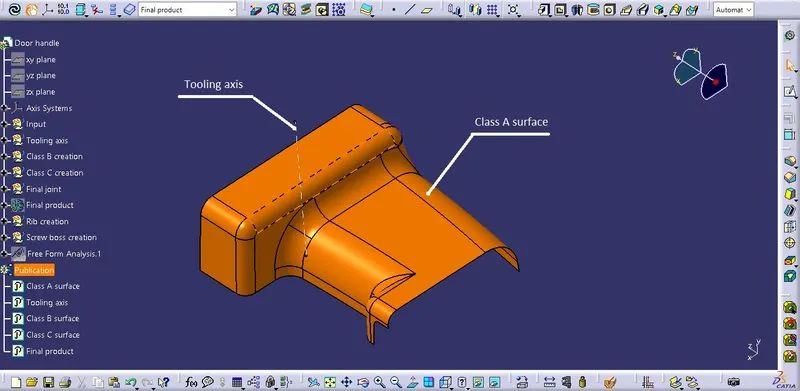
The class A surface is the aesthetic surface which is the visible part to the customers. The class A surface is developed into plastic product and engineering feature like ribs, screw boss etc are added as required by the designers. It should be ease for manufacturing & assembly.
Class A surface:
2.) Creating tooling axis:
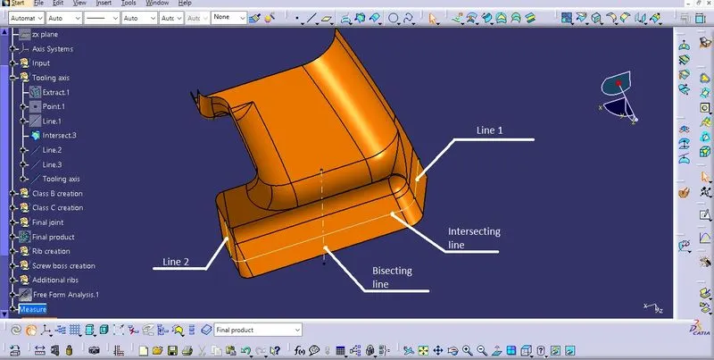
The tooling axis is responsible for the mold (core & cavity) movement. The tooling axis should clear the draft analysis. Complicated tooling axis can increase in cost and time for manufacturing. The tooling axis is created by bisecting method.
3.) Draft analysis for class A surface:
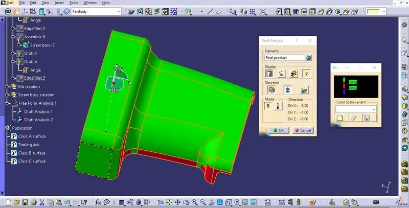
The draft analysis will show exactly the draft angle in each area, by which we can modify the tooling axis if it is not cleared the design rules.
The nominal draft angle is 3°
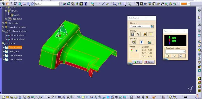
The red region has the draft value of 2.5 °,2.7°,2.8°,1.8° which can be acceptable.
4.) Creating B surface:
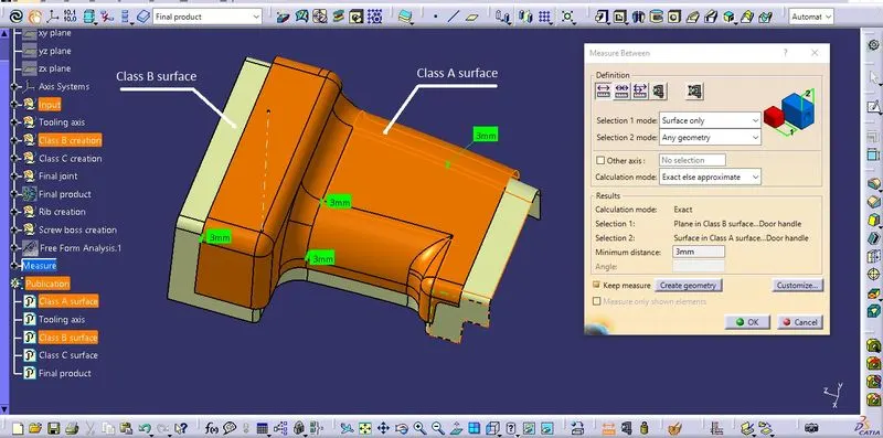
The thickness of the component is concidered as 3mm.
The class B surface is created by offsetting the class A surface and minor patches are modified by using tools like multiple extract, extrapolate, join.
5.) Creating class C surface:
The class C surface is formed from class A surface by using tools like boundary, sweep, extract, multiple extract, extrapolate, trim and join.
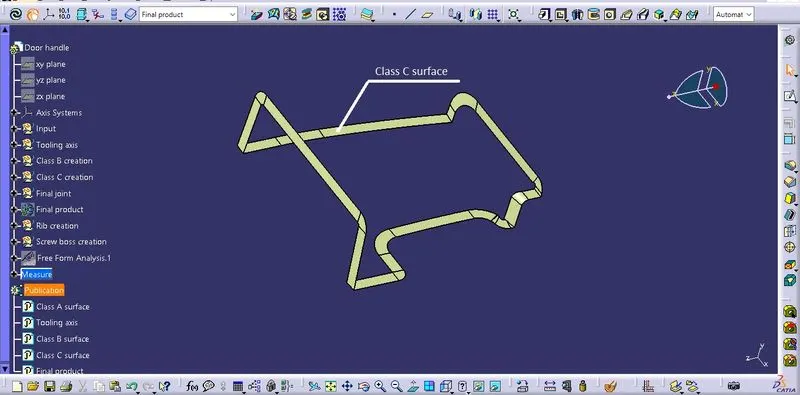
The class C surface is joined with class A surface and then trimmed with class B surface to form the final plastic product.
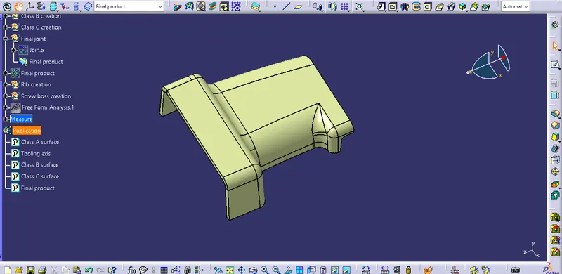
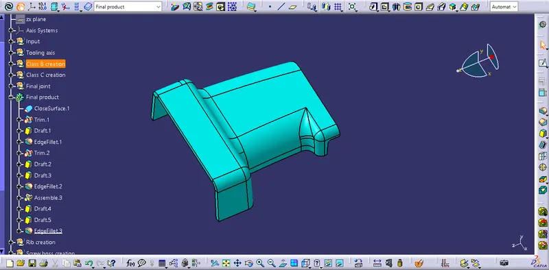
It is then converted to closed surface to form the final solid plastic component.
6.) Draft analysis for final plastic product:
7.) Adding ribs & gusset:
Ribs:
Ribs are the features in plastic injection molded parts. They are thin extension that run perpendicular from wall or plane. They are commonly used to provide additional support & strength to the part. Thickness and location are essential for rib design.
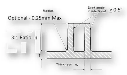
The given design rules for rib:
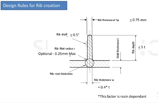

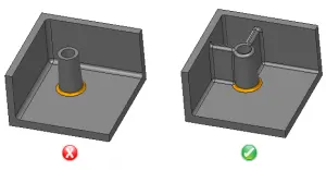
The ribs are designed with the given guidelines.
Screw boss:
Screw boss are typically used to assist in assembly, as a receptacle for a screw or threaded insert or as the locator for other part to mount in it.
The given design rules for screw boss:

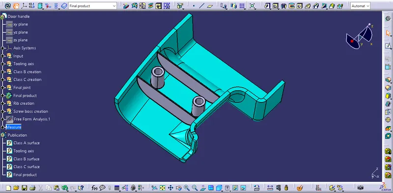
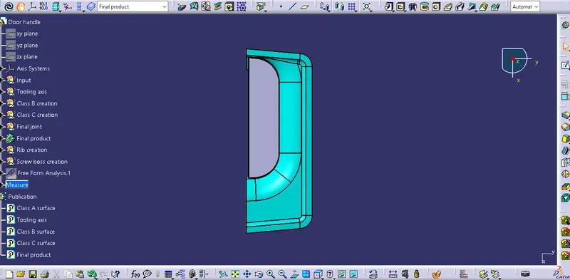
The final plastic design with ribs and screw boss as required:
Isometric view:
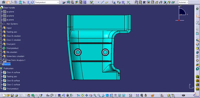
Front view:
Side view:
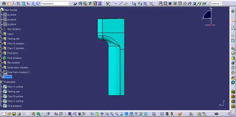
Top view:
CONCLUSION:
The door handle plastic design is created with the engineering fearures as required.
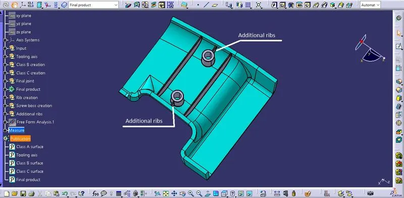
Additional ribs are added to the screw boss for extra support to withstand the load with the design guidelines. This is designed additionally apart from the design requirement.