Week 9 - Challenge 2 - Switch Bezel Design
SWITCH BEZEL:
OBJECTIVE:
To create switch bezel plastic component from the given class A surface as an input.
INTRODUCTION:
The switch bezel component is the frame part of window that holds the switch covers and buttons into place. Molding method is carried out by most the OEM's for manufacturing these products. So considering this manufacturing process the design of switch bezel is carried out.
Design consideration:
- The class A surface is the aesthetic surface
- The class B surface should have all the engineering features like boss, ribs, etc.
- Parting line should always coincide with the class B surface since flashing could affect the class A surface.
- Class C surface should clear the drafting analysis.
STEPS:
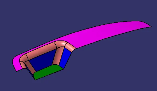
- Understanding the class A surface
- Creating tooling axis
- Draft analysis for class A surface
- Creating geometrical set for class B surface
- Creating class C component (thickening part)
- Draft analysis for final plastic component
1.) Understanding the class A surface:
The Class A component is called as the aesthetic design, which is the visible part of a vehicle. This class A component is given as an input for product designers. The class A surface is thickened and engineering features are been added. The design should be ease for manufacturing and assembly (DFM & DFA) .
Class A surface:
2.) Creating tooling axis:
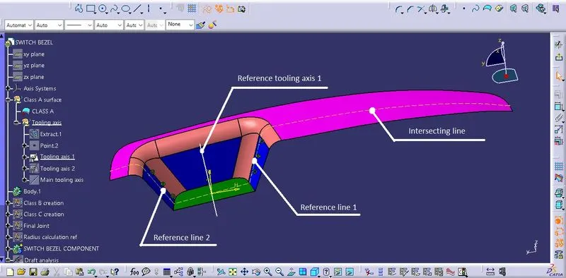
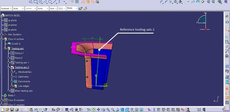
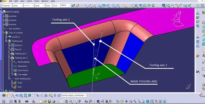
The tooling axis is decided by the designers from the class A surface. The tooling axis should be easy for manufacturing since complicated design can increase the cost and time for the product. The tooling axis is responsible for the mold (core & cavity) movement.
Since this class A surface has only three face, two different tooling axis are formed and bisect together to form the main tooling axis.
Reference tooling axis 1:
Reference tooling axis 2:
Main tooling axis:
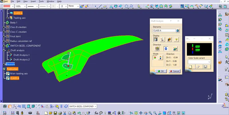
3.) Draft analysis for Class A surface:
Draft analysis carried out to avoid part being prallel to to the mold. Which cause more wear while ejecting the component out from the mold. It cause damage to the part and mold. A part can not be manufactured 90° parallel to the tooling axis, a small draft angle is given for ease removal of product from the mold.
The draft angle carried out is - 0.3° to 3°
The nominal draft angle is - 3°
4.) Creating geometrical set for class B surface:
The given thickenss is 2.5mm
The top, tapper & bottom surface are created by using tools like extract, untrim, offset, extrapolate.
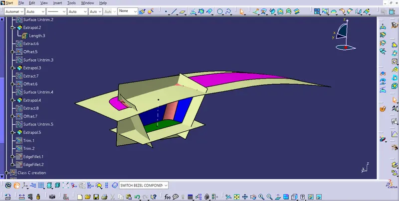
The class B surface is trimmed and fillets are added.
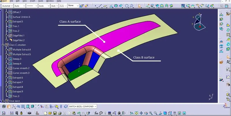
The fillet value given - Radius of class A - Thickness (15-2.5) & (14-2.5) = 12.5mm & 11.5mm
5.) Creating class C component:
The class C surface is the thickening part whis has 2.5mm thickness as required. The class C is created by using multiple extract, sweep, smooth curve, extrapolate, trim & joint commands.
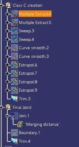
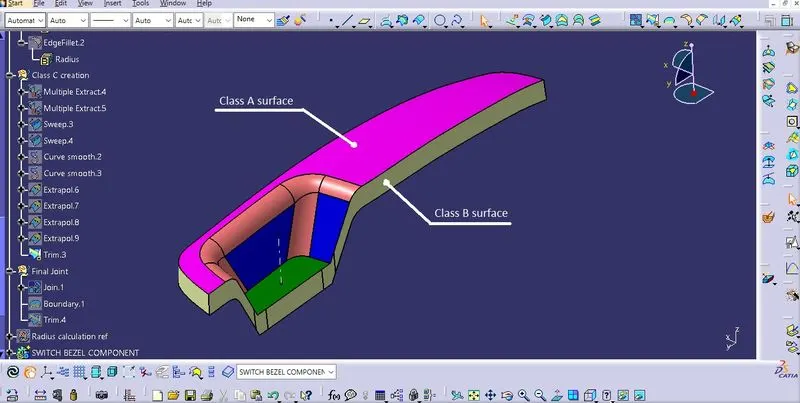
Finally Class C joined with Class A and trimmed with Class B to form class C thicken component:
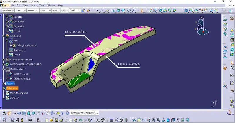
The Class C surface:
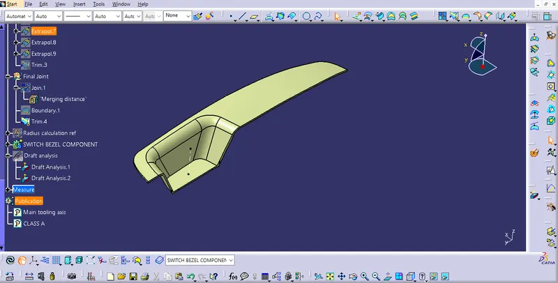
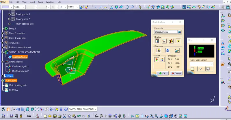
6.) Draft analysis for final product:
The class C component is forment into solid feature using close surface. The boundary conditions are applied to check for a closed boundary. And the solid feature is draft analysed.
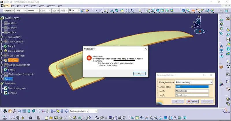
Draft analysis for final product:
CONCLUSION:
The switch bezel design is completed, all design guide lines are carried out. Draft analysis is carried out and results are clearing for the molding operation.