Week 9 - Challenge 3 - Bumper
BUMPER DESIGN:
OBJECTIVE:
To create bumper plastic componenet from the given Class A surface as an input.
INTRODUCTION:
A bumper is a structure attached to or integrated with the front and rear ends of a motor vehicle, to absorb impact in a minor collision, ideally minimizing repair costs.
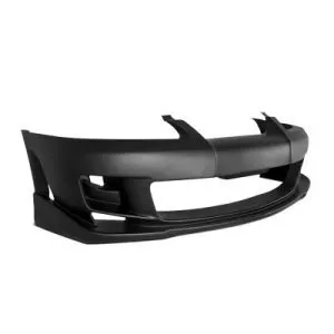
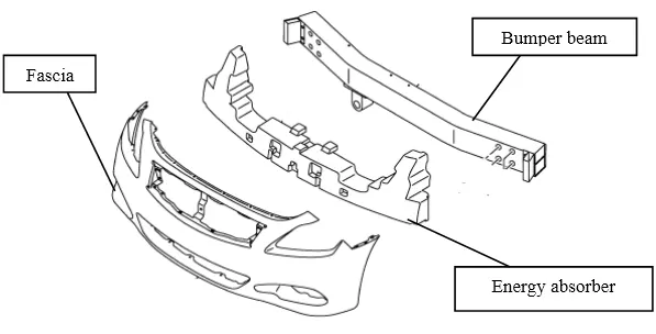
Automotive bumper design principle:
- Active safety
- Passive safety
- Harmony
- Easy installation and maintenance
Active safety: On the basis of maximally satisfying the function of use, the design of the bumper should comply with the regulations of the car protrusions, and the design should implemented a safe, reliable and resonable design concept.
Passive safty: When auto collides with the outside world, the bumper acts as a safety device for protecting the front and rear body, and has good energy absorption characteristics.
Harmony: Whether it is appearance, colour or quality perception, we can not only pursue the characteristics of a single bumper, but also maintain coordination with overall shape of the vehicle and integrate with the whole vehicle.
Easy installation and maintenance: The bumper and its adjacent component can not interfere with each other, the clearance should be reasonable, and the installation point should be set according to ergonomics.
DESIGN CONSIDERATION:
- The class A surface is the aesthetic surface
- The class B surface should have all the engineering features like boss, ribs, etc.
- The parting line should always coincide with the class B surface since flashing could affect the class A surface.
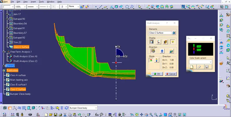
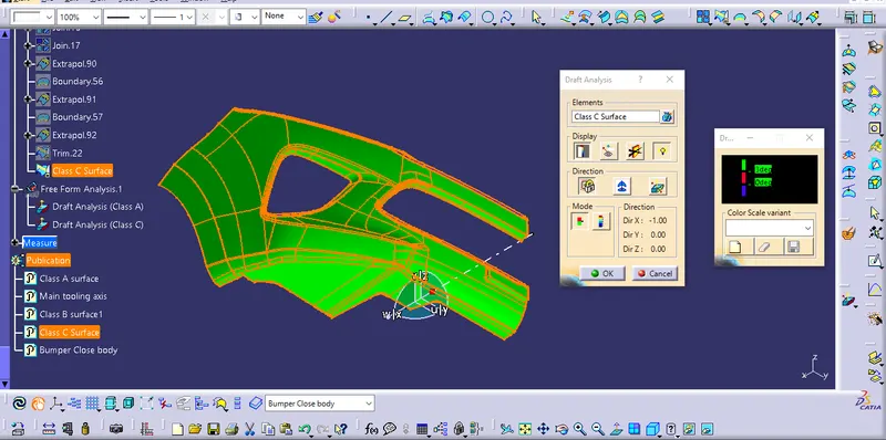
- The class C surface should clear the draft analysis.
STEPS:
- Understanding Class A surface
- Creating the tooling axis
- Draft analysis for class A surface
- Creating class B surface
- Creating class C surface (thickening part)
- Draft analysis for final plastic component
1.) Understanding class A surface:
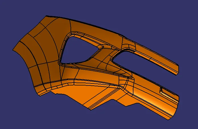
The class A surface is the styling surface with is the visible part of a vehicle. It should be aesthetically good as it is the first attraction for a customers. The class A surface is thickened and engineering features are added onto it. The design should the ease for manufacturing and assembly (DFM & DFA).
Class A surface:
2.) Creating tooling axis:
The tooling axis is decided by the designers from the class A surface. The tooling axis should clear all the surface from draft analysis, since it is responsible for the mold (core & cavity) movement. The tooling axis should be ease for manufacturing because complicated mold design which will increase cost and time.
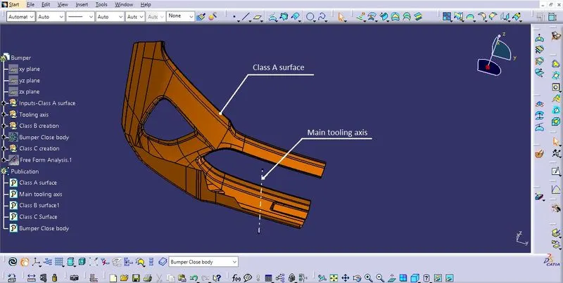
3.)Draft analysis for class A surface:
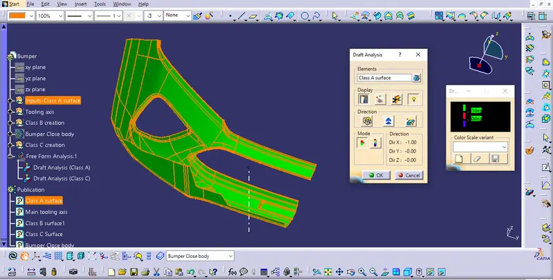
The draft analysis is carried out to avoid componenet being parallel to the mold, which cause wear and damage to part and mold while ejecting. A part can not be manufactured 90° parallel to the tooling axis. A minimal draft angle in included for ease ejection of componenet from mold.
The draft angle carried out is - 0.3° to 3°.
The nomial draft angle is - 3°
4.)Creation of class B surface:
The given thickness is- 3mm
The class B surface is created by offseting class A surface to 3mm as required.
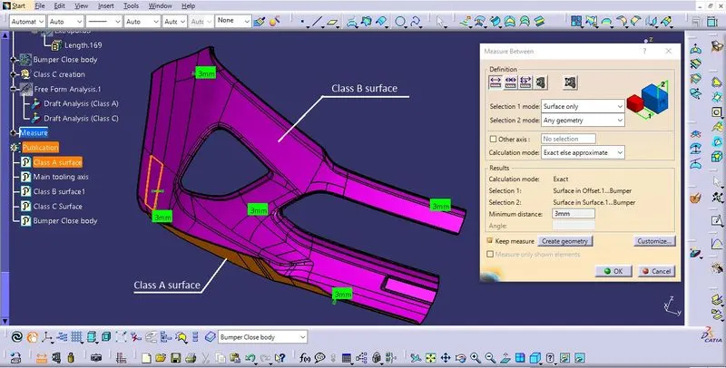
The Class B surface which we offset has minor patches or gaps observed, which is cleared by using tools like multiple extract, extrapolate, trim & edge fillet.
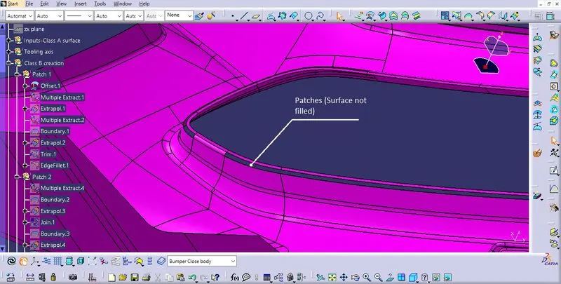
Class B surface is formed:
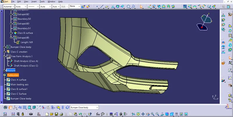
5.) Class C creation:
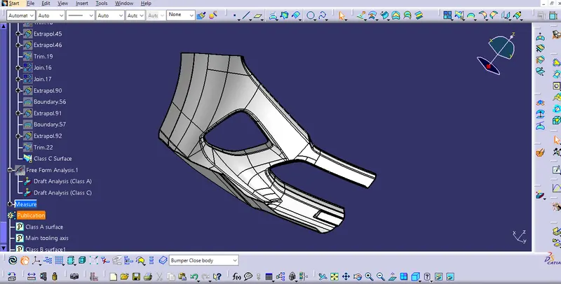
The class C surface is created by sweep, extrapolate, trim, join using class A surface.
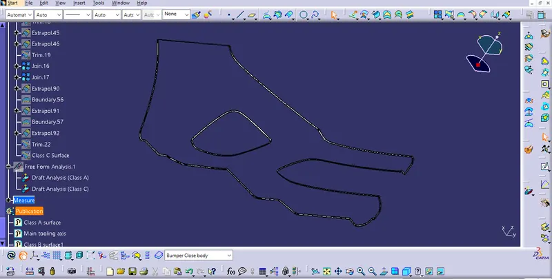
The class C surface is joined with class A and trimmed off with Class B surface.
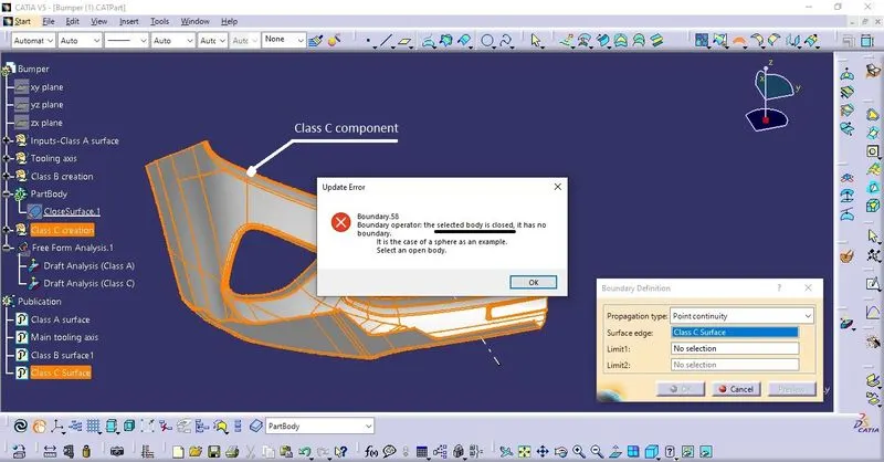
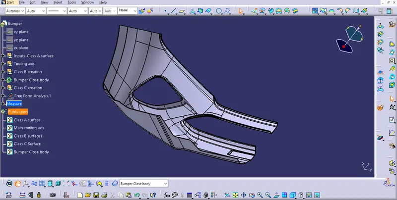
The class C componenet is ensured for closed boundary condition.
6.) Draft analysis for final product:
Top view:
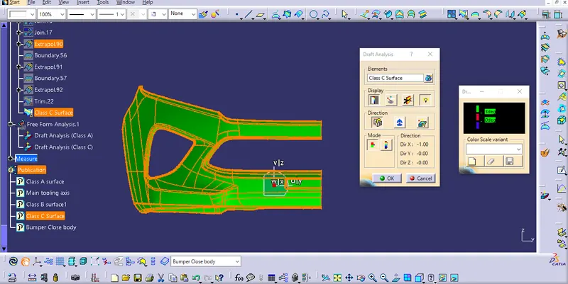
Front view:
Isometric view:
The final closed body is created:
CONCLUSION:
The bumper plastic component is created throught the given class A surface with all the design considerations.