Week 12- Final project
Final project - Door Trim Panel
Door panels serve as an interface between the interior of the car and the inner components of the door. They are designed in such a way that they are concealing intricate electrical and mechanical components and features for operating lock and windows.
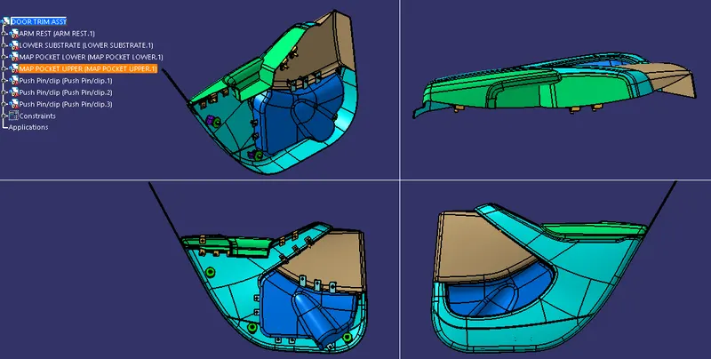
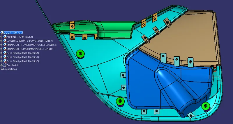
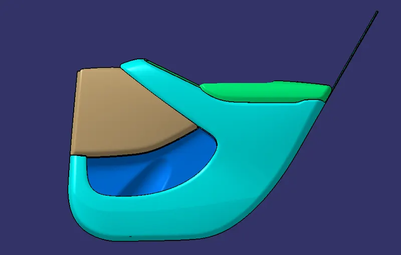
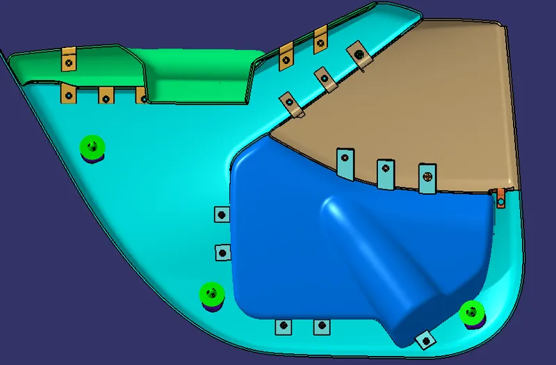
In this project, an inner car door panel is given with class A surface, to create the door trim panel. Door Trim panel consisting of Lower Substrate, Upper map pocket, Lower map pocket, and Door armrest.

Given Inputs
Class A surface with Master Section
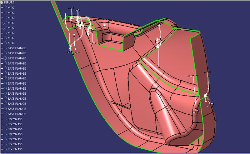
Class A Surface
The surface of a component which is smooth and visible to human eye after the part is assembled, which is given as an input to the plastic designer to work on it.
Class B Surface
It is the surface which comes below the class A surface with a particular thickness. This surface contains engineering features of a plastic model like bosses, snaps, Dog house and ribs.
Class C Surface
It is the surface which joins class A with class B surface.
AIM
With the given Class A surface as reference for all four components of the Door Trim Panel
- Create tool axis by either considering normal to surface method or bisecting method.
- Ensure the Class A surface is clearing draft analysis with the tool axis created.
- Create Class B surface by creating an Offset of Class A, by measuring the thickness in Master Section.
- Create Class C surface along the boundry of Class A by sweeping and extrapolating with reference to Class A.
- Join Class A and Class C.
- Trim Class B with Class A+C. This will result in a closed surface. Add the close surface feature to create a solid body.
- Once the Solid body is created, Create Flanges with reference to Master Section for Heat Staking and 4 Way Locators.
- Using the 3-2-1 fixation strategy locate points on the Class B to add engineering features like Dog House, Push Pin, Heat Stake and 4 Way Locators.
Creation of Tool Axis
Tooling axis is the direction in which the core and cavity opens. Tooling axis depends on the ease at which components can be ejected from the mould after injection.
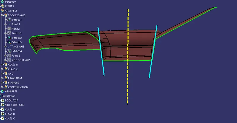
Bisecting Method
- Create a point on the class A surface to move the main tool for component creation on the base surface.
- Using Projection command select the YZ plane as the reference, project the edges with maximum possible draft angles.
- After that, select the Line command and join the vertices.
- Bisect those two lines over the axis point we created.
Normal to Surface Method
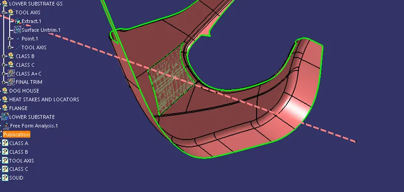
In this method, consider a face with flat surface or plane having large number of flat surfaces, and draw a normal by extracting the face and make sure the tool axis can clear the draft analysis for the whole body.
Draft Analysis
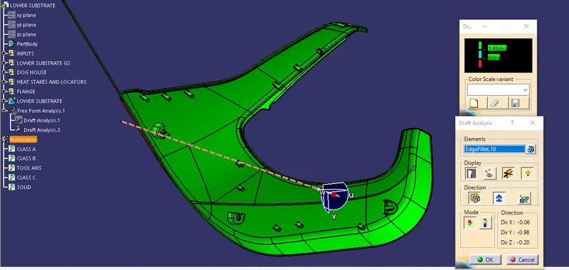
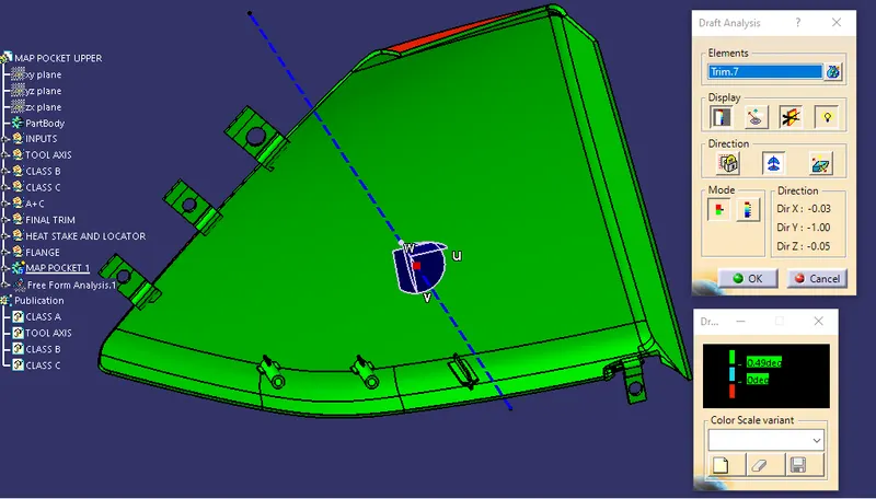
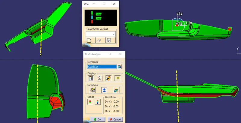
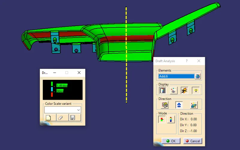
Draft analysis is used to see if the draft of a part is sufficient for the molding process and if the part will separate correctly from the mold.
- Change meshing mode to "material" in the view mode dialog box.
- Click on draft analysis option.
- Zoom out and locate the compass, drag and drop the compass to coincide the tool axis to define the new current draft direction.
- Choose the class A surface/ Solid part to perform draft analysis.
Under display option, use the colour scale to analyze the dynamic draft of the component.
Lower Substrate
Map Pocket Upper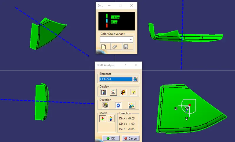
Map Pocket Lower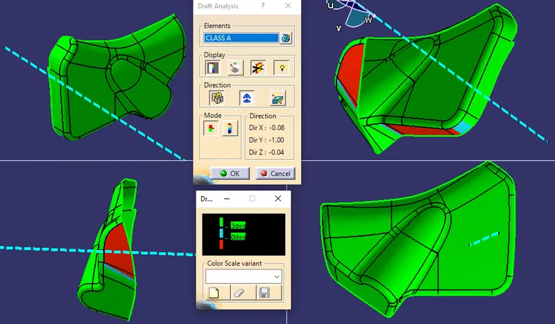
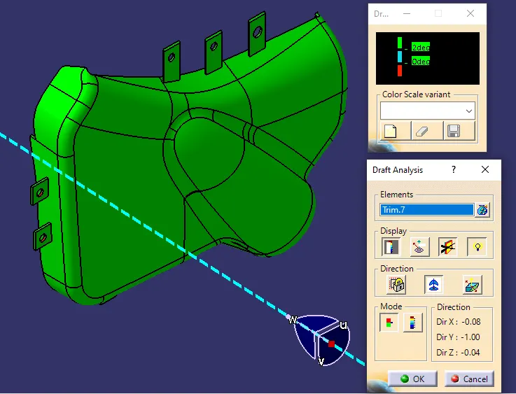
Arm Rest
Engineering/ Attachment Features
1. Flanges
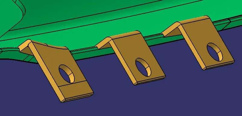
A flange is a protruded ridge, lip, or rim, either external or internal, that serves to increase strength for easy attachment/transfer of contact force with another object. In this project Flanges are provided for easy attachment of Heat stakes and 4 Way Locators.
For creation of Flange, the sketches from Master section is taken as reference.
2. Dog House
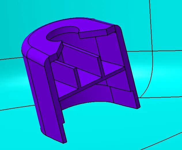
Dog house is an engineering feature used in plastic trim design. They are used as supporting features. Other engineering features like Push Pins, locators etc. are mounted on them to increase their strength.
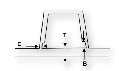
Design Considerations
- Doghouse wall thickness at the intersection of the part wall ( C ) should be 40% or less than the main wall stock ( T ).
- The height of ( B ) should be between 3.0 – 6.0 mm
3. Push Pins
Pushpin is a plastic fastener used to join two components. They are designed so that they can be easily attached and removed whenever needed. Dog house is provided for rigidity and distance to maintain the Class A aesthetic and also facilitate easy removal.
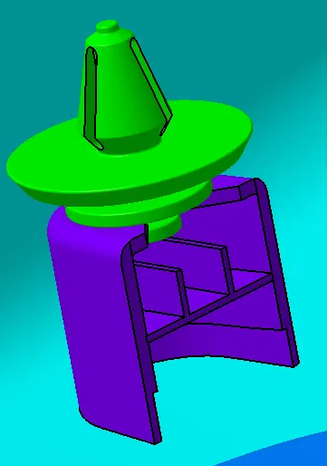
Push-Pin With Dog House Assembly
4. Heat Stakes
Heat Staking is an assembly method, that uses controlled melting and reforming of a plastic boss to lock another plastic/metal component of an assembly in place.
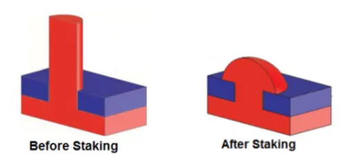
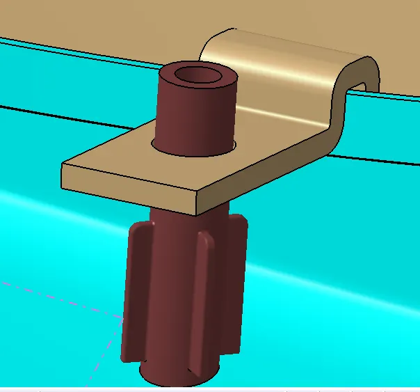
Heat stake with Ribs and flange - Assembly between Lower Substrate and Map Pocket Upper
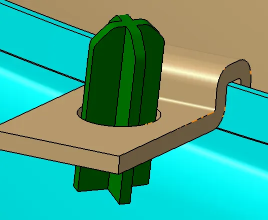
5. 4 Way Locators
These locators are used to arrest degree of freedom in +X, -X, +Y and -Y and also make it easier for assembling two parts together as the first contact will be between a flange and a locator.
Final Assembly