Week 12- Final project
ANSWERS
INTRODUCTION
It Involves
Concept sketches
Class A creation
Clay modeling
NPD CAD
CLASS A
A sketch can be transformed into a controllable surface in a three-dimensional virtual space with the use of specialised Class A Surface creation software. Three images—the top view, side view, and front view—would normally be needed.
Clay modelling and class A go hand in hand. For a realistic exhibition, a clay replica of the interior and outside of the automobile would be created.
NPD CAD
The designing of parts for assembly with dimensions happens during new product development.
For the given input, we will now engage in the new product development phase.
MATERIALS
Polypropylene (PP), Acrylonitrile Butadiene Styrene (ABS), and Poly Vinyl Chloride (PVC) are used to make interior trims.
Plastics are utilised widely because they are lightweight and cost-effective. It also provides a surface that is attractive.
CLASS A CREATION
from the specified Enter the appropriate class. By combining the surfaces, a class A surface is produced. Check the surface's continuity.
TOOLING AXIS CREATION
The direction in which the mould opens and shuts is known as the tooling axis. additionally the places that require drafting. Analyse the part, such as the walls, and discover the potential tooling axis.The bisecting approach can also be used to produce tolling axes.
The tooling axis is now generated in the Z direction for the door arm. The slider axis was also developed with drawing in mind. Door arms are divided into two segments.
The tooling axis is taken in the Y direction for the lower substrate.
CLASS B CREATION
B surface is the engineering surface where all the b side features like rib, dog house screw boss, and locator and heat stake are designed.
The class A surface is offset to 2.5 mm to get the b surface.
CLASS C CREATION
The C surface is the surface that runs parallel to the tooling direction and joins the A surface and B surface.
The door arm is swept in the direction of the tooling axis while the class A boundary is swept with reference to the surface in door arm 1.
Class A and B surface boundaries in the lower substrate are divided into many sections, and the A, b, and c surfaces are then linked to form a closed surface.
The sweeping is done in the draught direction in the map pocket.
Class A, B, and C surfaces are combined to create a closed surface after the creation of the C surface.
In order to verify whether a boundary is formed, click the boundary. If an error is displayed, we have a closed surface.
Switch to component design after that, adding a closed surface to form solid body.
B SIDE FEATURE CREATION
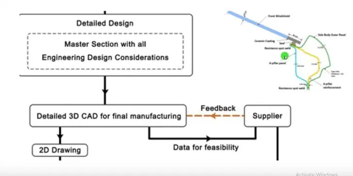
The master section for the attachment method is provided, and we are required to develop the b-side features at the appropriate surfaces
Master sections serve as a reference for the design specifications that, after considering technical surfaces, determine component packing.
The evaluation of master section performance during the vehicle concept design phase is based on reference vehicle data and the expertise of the structure design engineer.
RIBS
Ribs offer a way to add strength and stiffness to moulded items at a reasonable cost without adding to their overall thickness. They also help with alignment, locate and halt assembly parts, and act as brakes or guides for mechanisms.
HEAT STAKES
To connect parts made of similar or incompatible materials, heat stakes are employed.
A controlled melting and reformation of a plastic or metal assembly component in place is known as thermal staking. The component that is going to be locked into place has a hole through which the plastic stud extends.
DOG HOUSE
A supporting component in plastic trim designs, the dog house is an engineering feature. To boost their strength, additional features like locators are installed on them. They stop the component from breaking during ejection.For a dog house, ribs are provided. The dog home is equipped with a push clip.
DRAFTING
To facilitate easy part ejection, draught provides angles or tappers on product features such walls, ribs, and bosses that are parallel to the path of release from the mould.
Draught addition aids in portion release. The majority of components or applications need for a minimum of 0.5 to 1 degree, while 3 degree is often regarded as the standard.
3 degrees is the ideal draught for a component.
B-side features must have a minimum slope of 0.5 degrees.
Draught analysis is performed for the class and final part body along the tooling axis.
alter the view mode to adjust the view parameters, then select the draught analysis feature to insert.Compass should be placed on the relevant tooling axis.It is formed to analyse the draught.green above blue 3 degrees negative draught, red at 0 to 3 degrees
PARTING LINE
The line separating the core and cavity portions of a moulded object is known as the parting line.
The parting line is determined by where the B surface and class A-C join intersect.
BOOLEAN OPERATION
The idea of a boolean operation originated in mathematics. The Venn diagram principle is applied.
The b side features are added, union-trimmed, and removed from the corresponding part body using boolean operations. The lower substrate is supplemented with heat stakes. To attach the door panel, a lower substrate is made for the dog housing.
APPLY MATERIAL PLASTIC IS USED
As a result, the desired result is produced, and the final out body door trim panel with B side features is obtained.creation of tooling axes
The final part body and class A draught analyses have been completed.
dividing lines
The creation of B side features with reference to the master section.
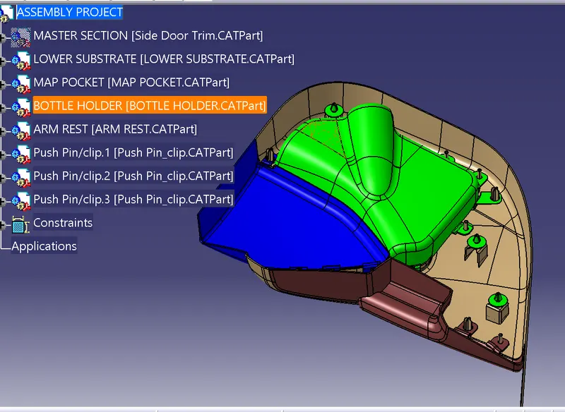
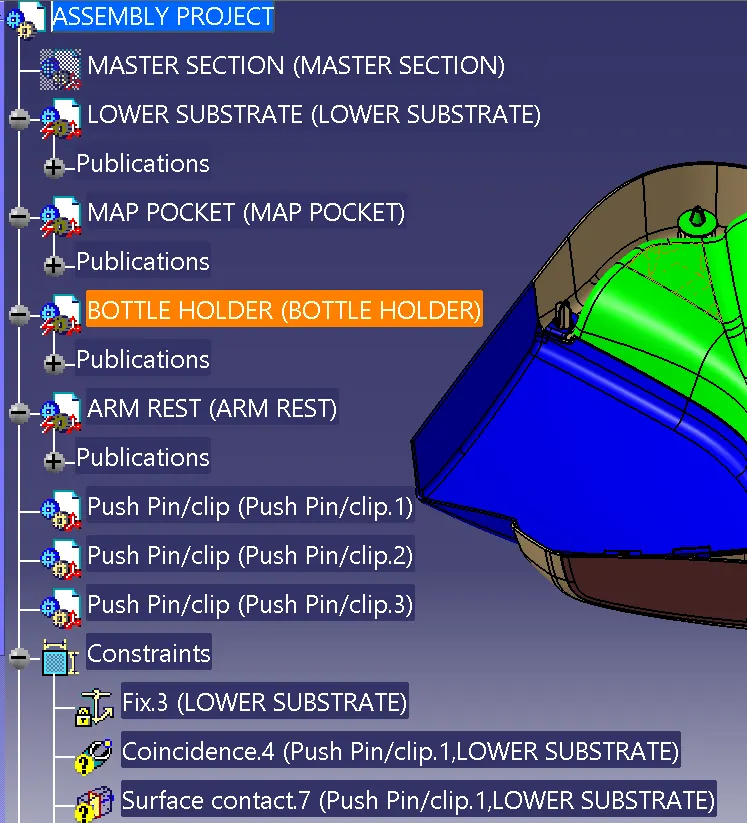
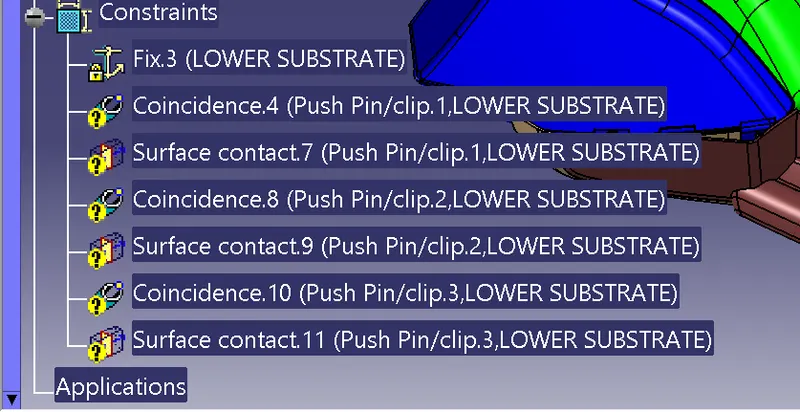
TREE STRUCTURE