Week 12- Final project
AIM :- To create a CAD model for door trim panel's parts by considering the given inputs of class A surface along with master section by following the design rules followed in OEM and tier1 companies.
OBJECTIVE:
To create
- Class B & Class C surface From the input Class A surface From the OEM.
- Closed solid body using nominal thickness from master sections.
- Engineering features like doh house, heat stakes, flanges etc with master sections.
- Tooling axis and lifter axis for the parts.
- Draft analysis for all parts and engineering features & explaination.
- Cat part for individual parts and Cat product attaching all parts together.
Tooling axis And Draft analysis
Tooling axis is defined as such all the features of the part can be manufactured easily. so here we followed the below steps to create the tooling axis.
- Tooling Axis created for the parts.
- Different ways of tooling axis creation is followed in OEM.
- Bisecting method, point and direction are methods used here.
- Side core axis or lifter axis is also defined when needed.
- Draft is done on the Class A surface of the parts
- Change it to material in customise view.
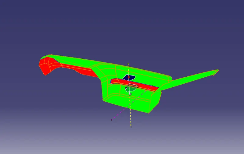
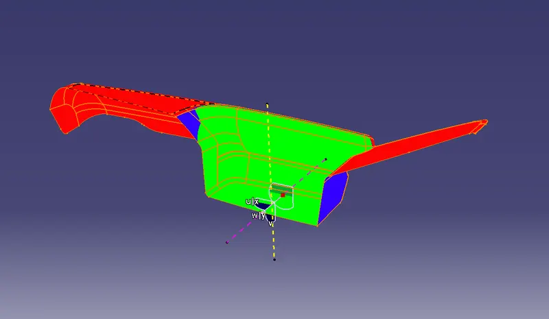
- Click the Draft analysis tool and click the surface and align the compass to tooling axis.
- 3 degree is the clearing angle
- Green Color shows Cleared surfaces.
- Few parts are defective so those sections not cleared the 3 degree. Kindly consider
Input
Given CAD Data
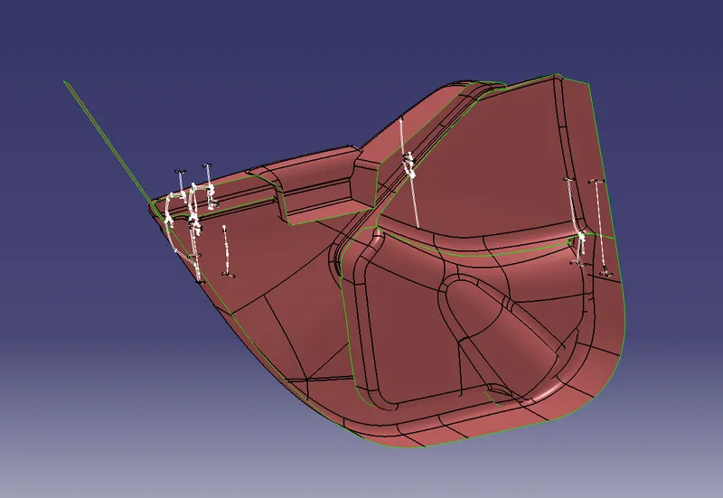
Image shows given Class A data with Master Section Of Door Trim Part.
Based on the knowledge that has been gained by taking the Plastic Design Course by CATIA V5 I have develped Class B Surgaces, Class C Surfaces, tooling axis for every single part, also, I found a strategy to assemble the four seperate parts into one part design by creating engineering features such as Heat Stakes, Ribs, Dog Houses and Flanges.
1. Armrest Part
Class A
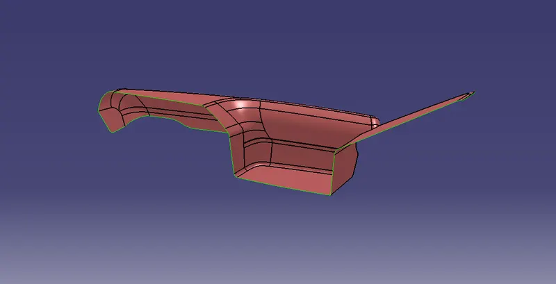
Given class A was having some impurities. As shown below.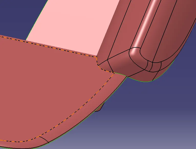
There can be seen open boundries which shows part surface is not joined properly.
Can be found by 2 methods
1 is to by clicking on join command and check for the open surface boundries.
2 is to by selecting highlight open boundries in the opntion menu.
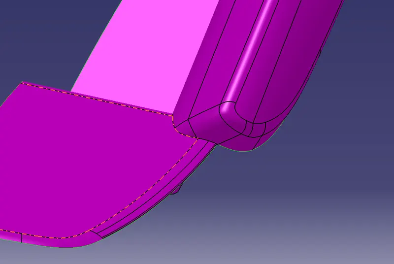
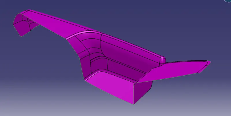
Using Extrapolate,split,trim,join,sweep commands Recreated the class A surface. Imgae shows Improved Class A Surface.
Tooling axis
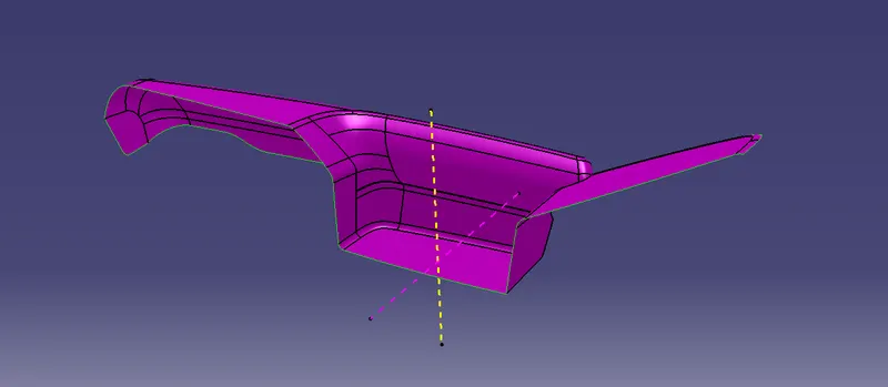
Main Tooling Axis and Side Tooling Axis are created in such way to provide drafting.
Draft analysis
Class B
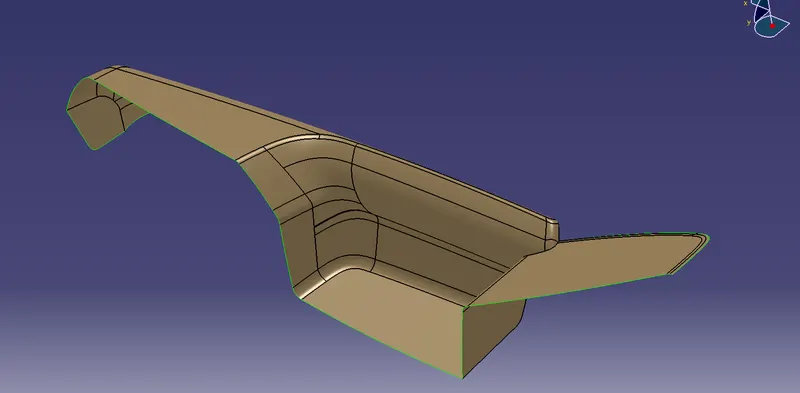
Class B is created by offseting Improved Class A by 2.5 mm as per the master section.
Class C
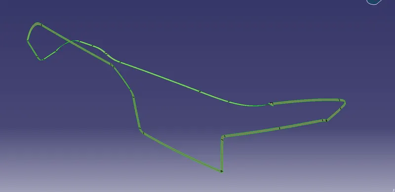
Class C is created by sweeping Improved Class A Surface and it has been trimed with Class B Surface.
Closed Surface
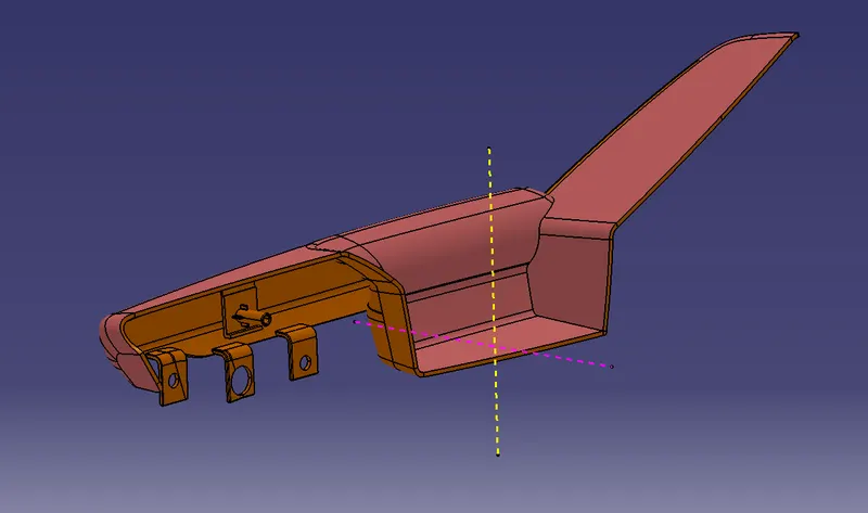
In oder to Join the Armrest body with the other bodies, I created 4 Flanges seperatly with counter holes, Flanges are different based on the engineering features will be held. Then these flanges are assembled to the main body (Armrest) by unitrim feature.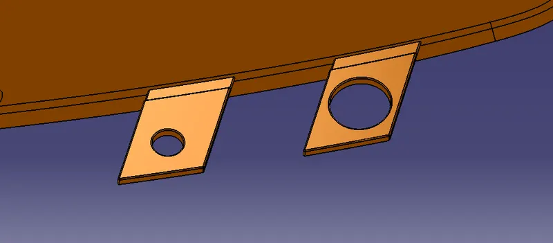
 Clearing side core axis
 Clearing along main tooling axis
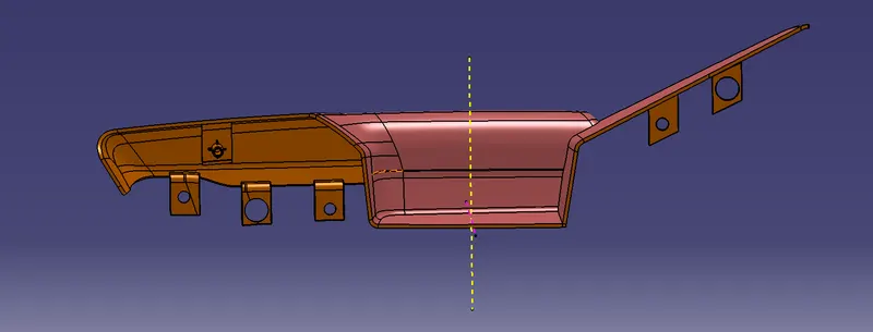
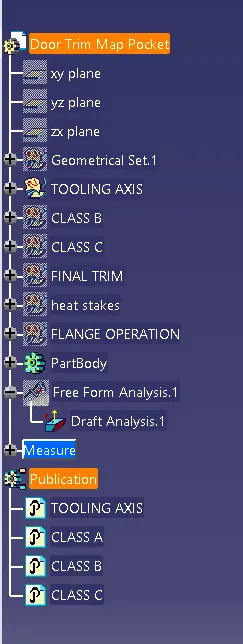 Tree structure
2- MAP pocket part
Given Class A
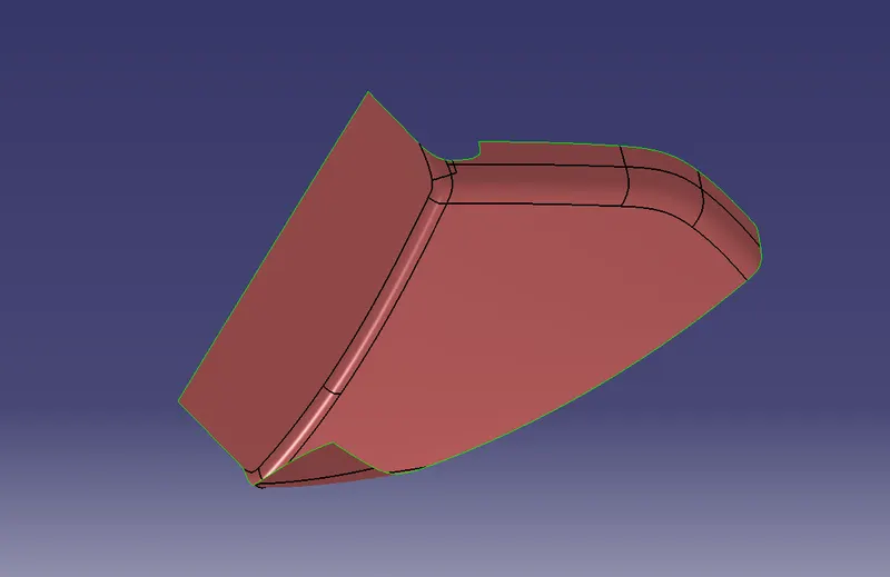
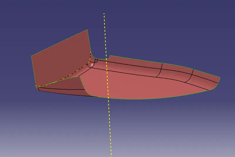 Tooling Axis
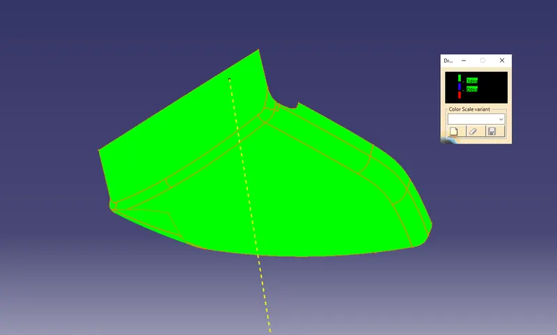 Draft analysis
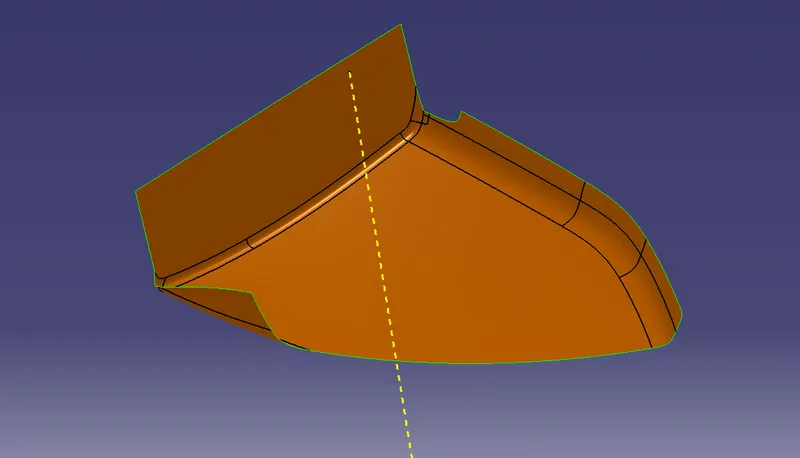 Class B surface
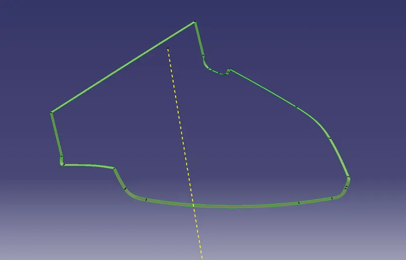 Class C surface
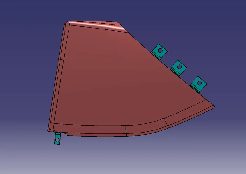 Closed Surface
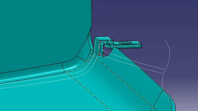
In oder to Join the Map Pocket with the other bodies, I created 4 Flanges seperatly with counter holes, Flanges are different based on the engineering features will be held. Then these flanges are assembled to the main body (Map Pocket) by unitrim feature.
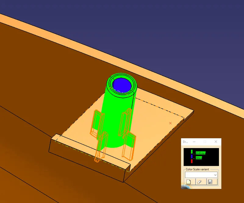
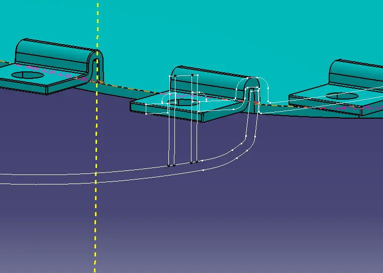 Flanges followed by heat stakes
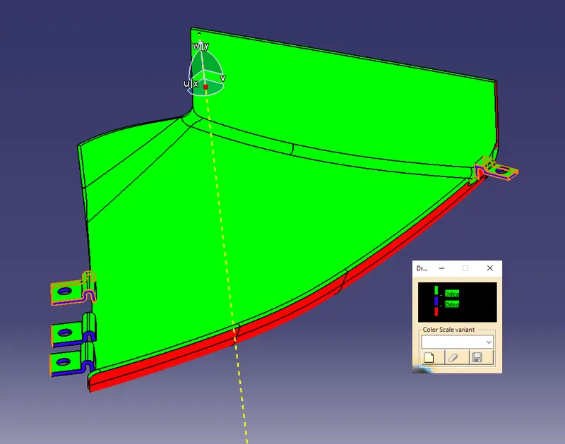 Draft analysis for final surface
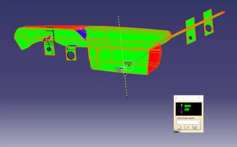
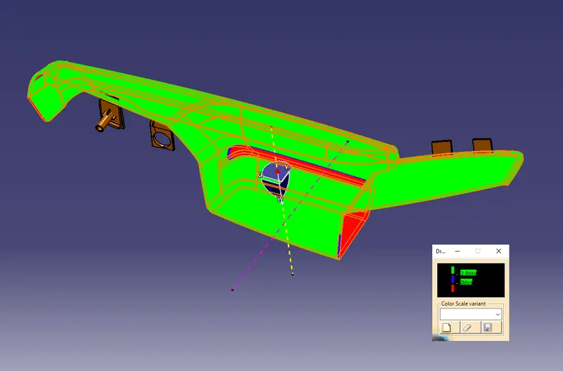
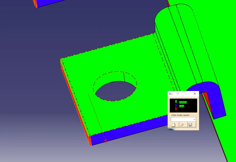
By applying drafting analysis at 2.9 Deg, we can see must bodies are been cleared. As Green set at 2.9 degree, blues is Zero and less than Zero it is red colored.For the Flanges is set at 0.45 at it is drafted to 0.5 Deg.
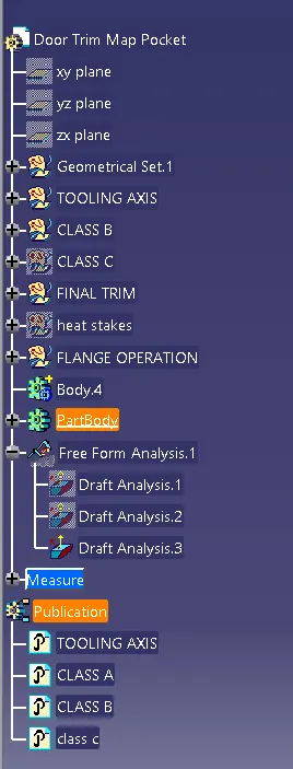 Tree Structure
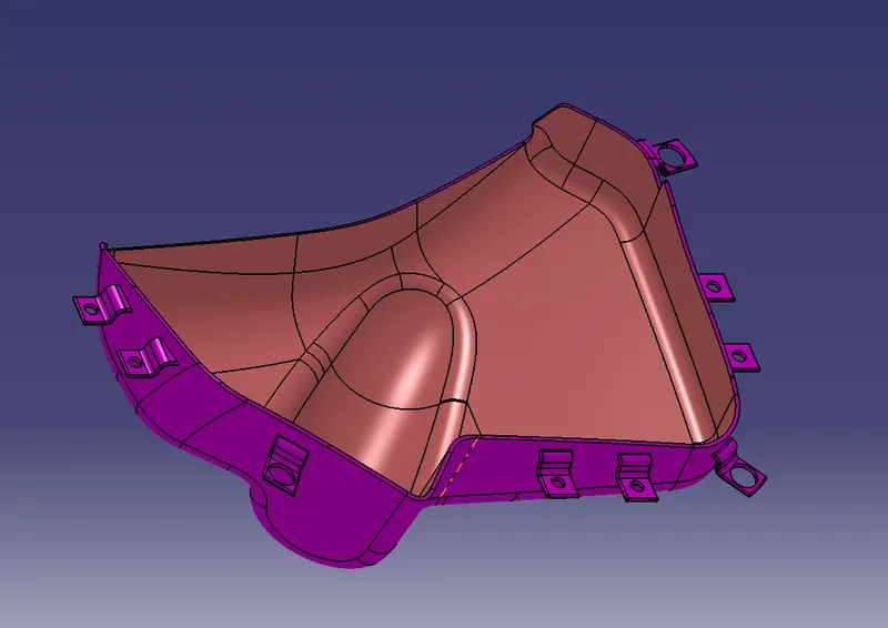
3- Bottel holder part
Class A
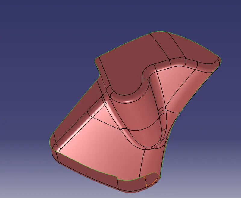
Main Tooling Axis and Side Tooling Axis are created in such way to provide drafting.
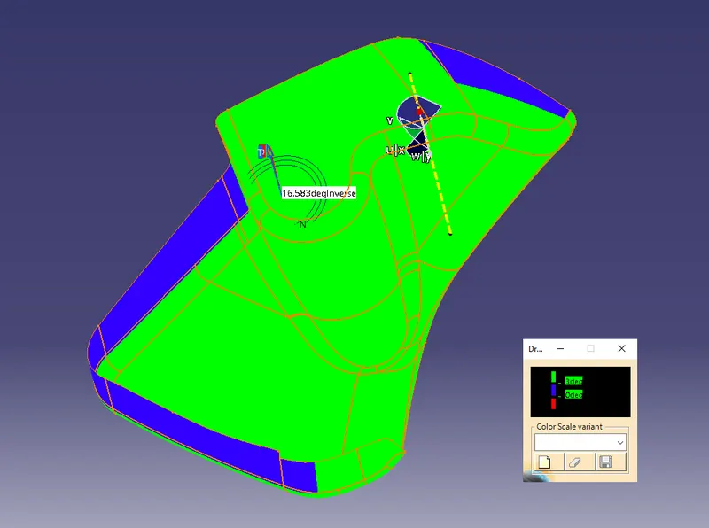
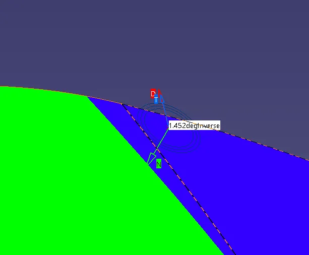
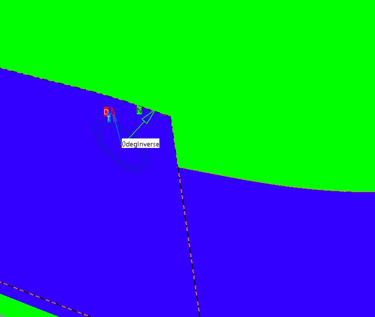
In class A Draft analysis result can see there are some uncleared surfaces which is showing in Blue color. having minimus draft of less than 2 degrees as shown below
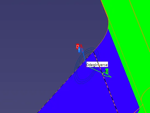
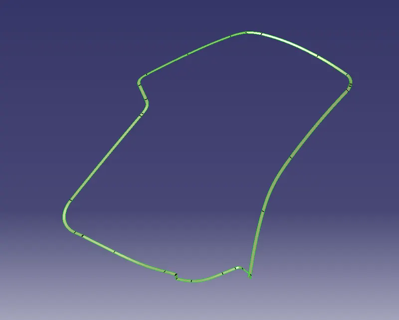
Class B is created by offseting Improved Class A by 2.5 mm as per the master section.
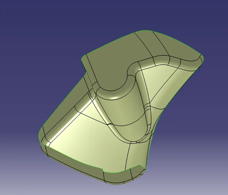
Class C is created by sweeping Improved Class A Surface and it has been trimed with Class B Surface.
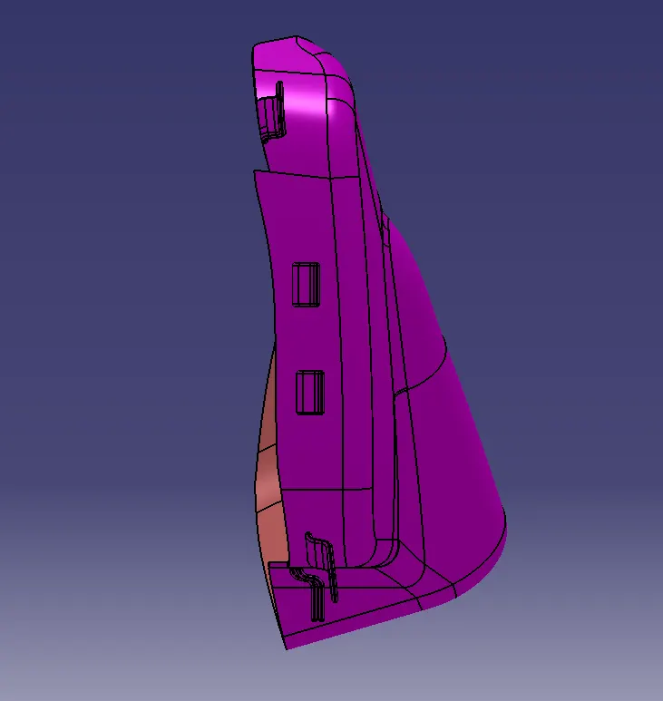
Cosed Surface Body with all attachments
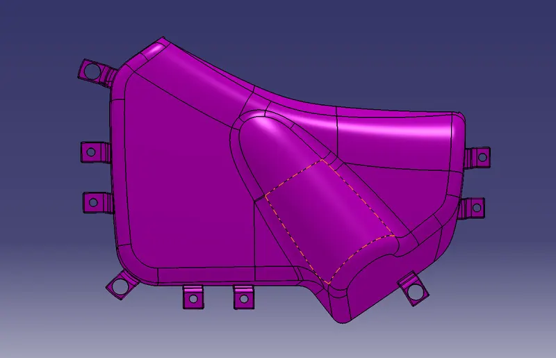
In oder to Join the Bottle Holder with the other bodies, I created 9 Flanges seperatly with counter holes, Flanges are different based on the engineering features will be held. Then these flanges are assembled to the main body (Bottl Holder) by unitrim feature.
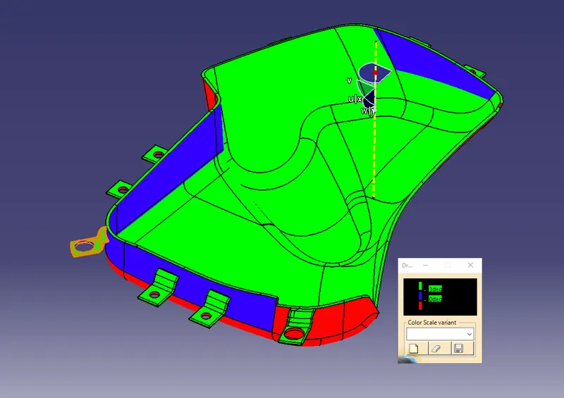
By applying drafting analysis at 3 Deg, we can see must bodies are been cleared. As Green set at 2.9 degree, blues is Zero and less than Zero it is red colored. As it is shown in the above image that in Class A Surface there is some patches an not be cleared by a draft angel of 3 Deg.
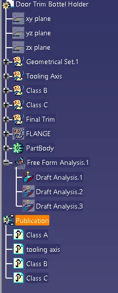 Tree Structure
4- Lower substate Part
Class A
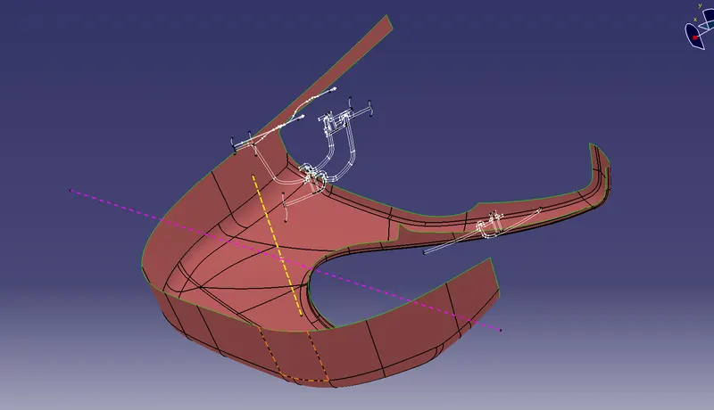 Class A with Master section
Main tooling axis in yellow clears main part and lifter axis in pink clears engineering features and dog house creation.
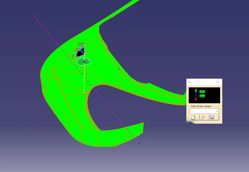
By applying drafting analysis at 3 Deg, we can see must bodies are been cleared.
Class B
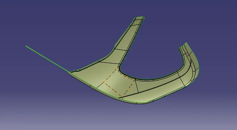
Class C
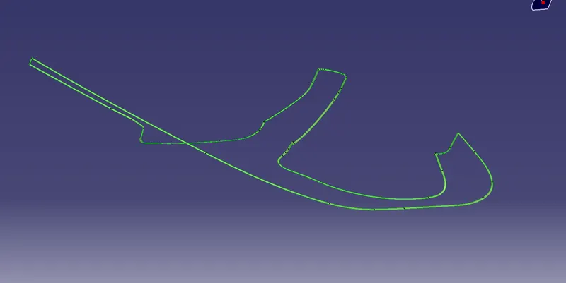
Closed Body with attachment engineering features
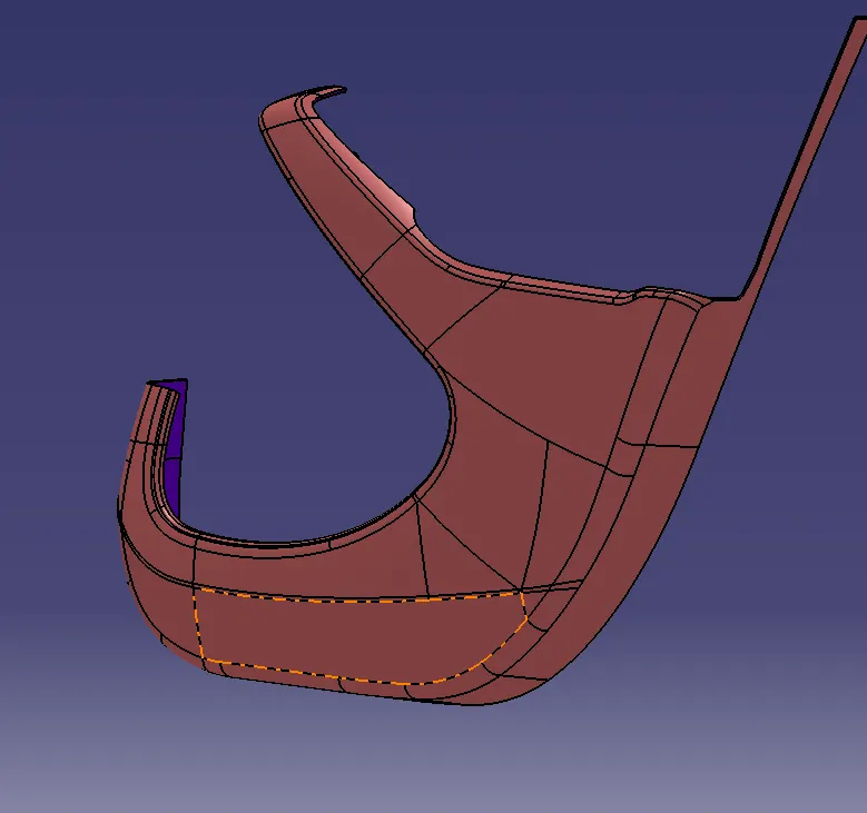
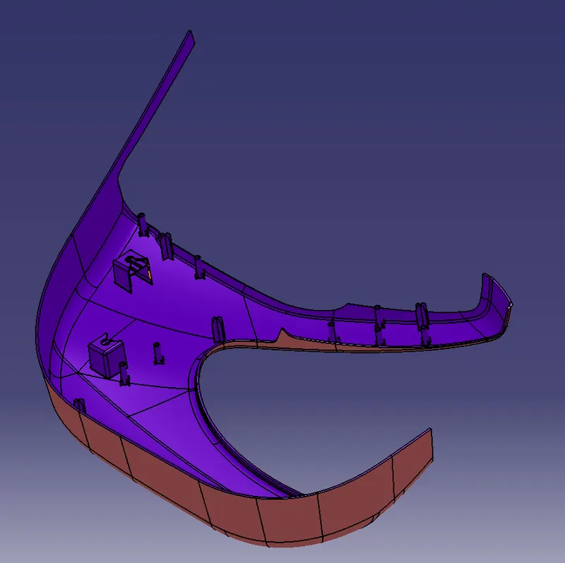
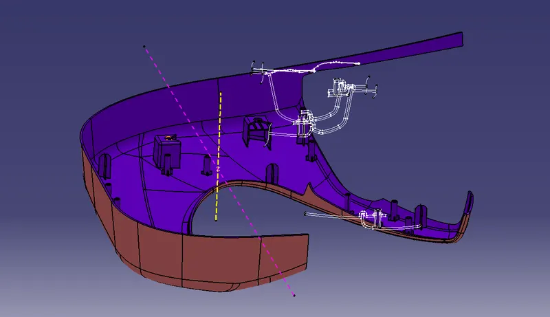
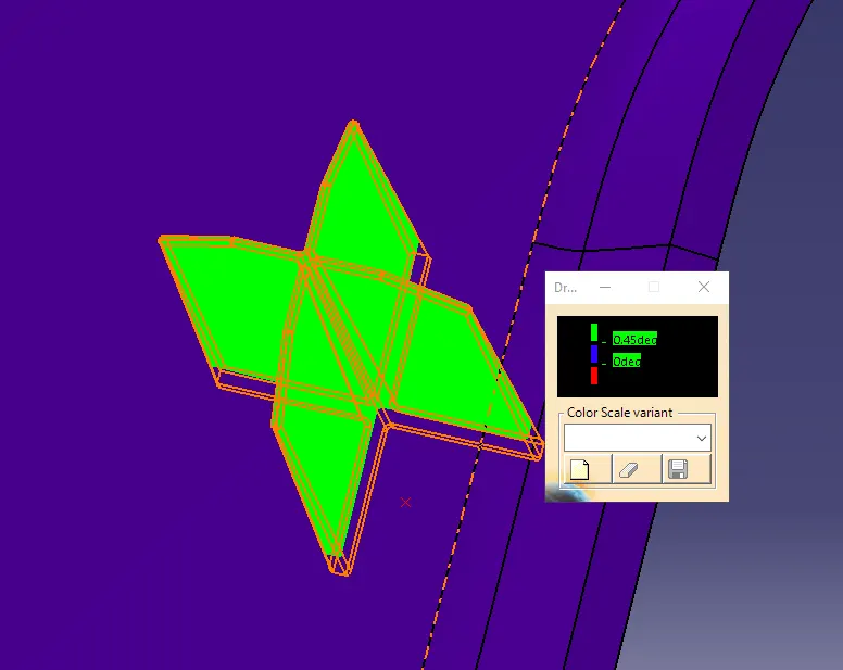
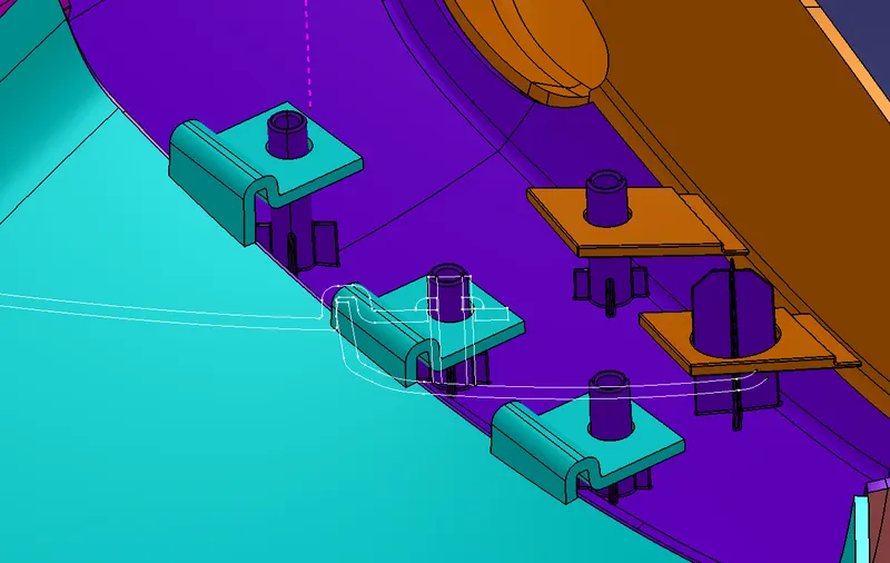
In oder to Join the Lower Sustrate with the other bodies, I will be using the Lower Subtsrate as the main body where other can be installed accoring to it. All connecting engineering features are created attched to this body while flanges will be conecting this main body to other bodies. two dog houses are created, 13 heat stakes and five 4 way lockers are created and attached to this body.
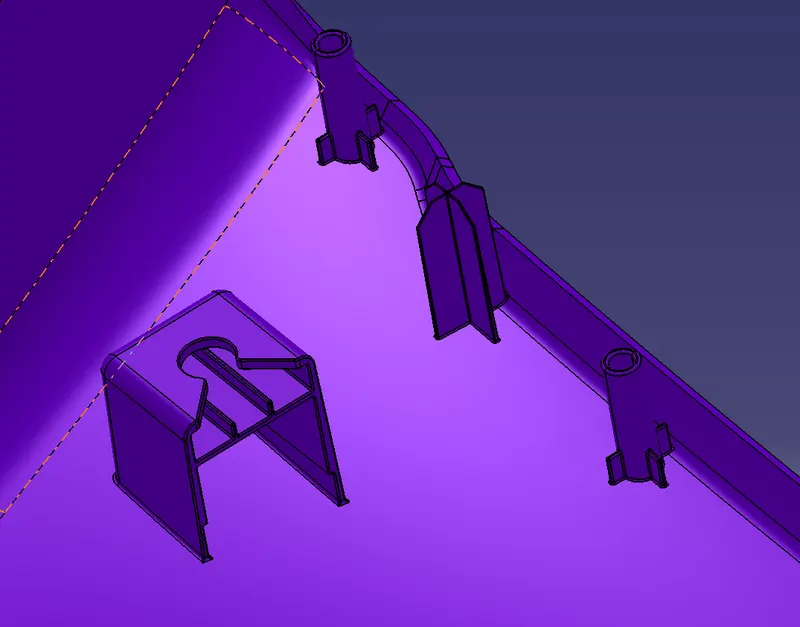
Dog house for push pin to lock
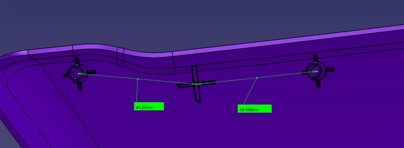
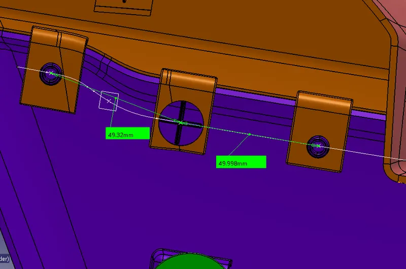
Engineering features 4 way locater and heat stakes provided at 50 mm of distance according to the design rules.
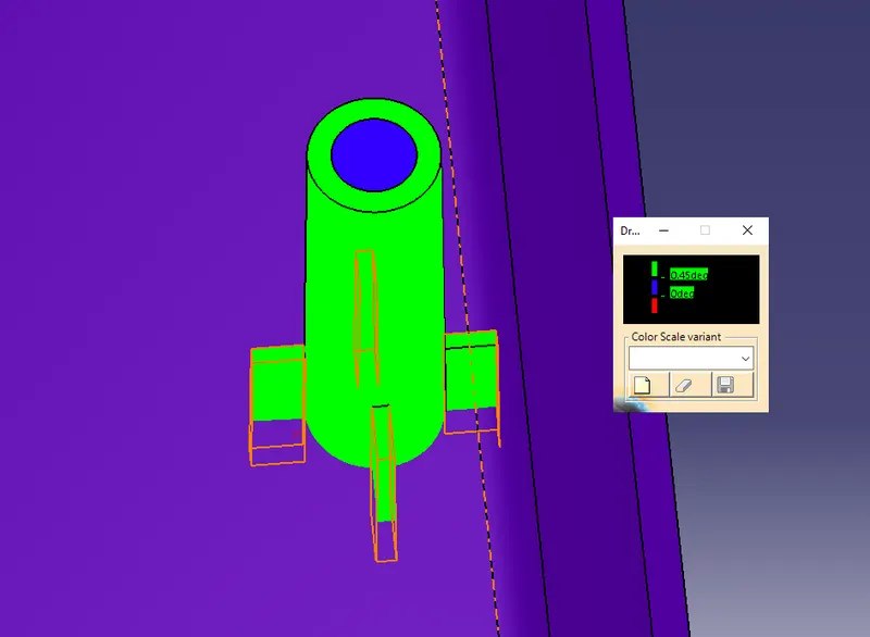
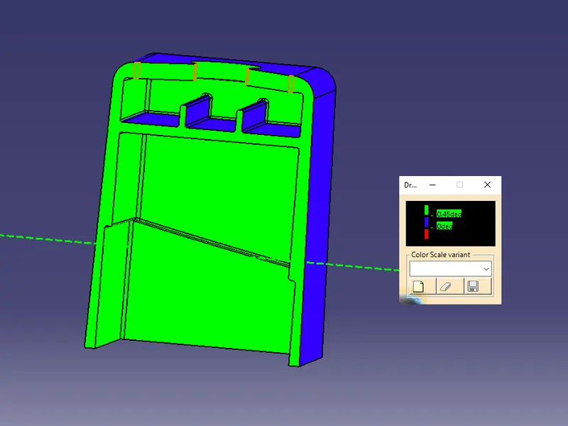
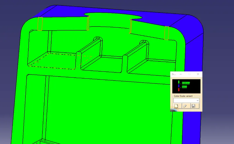
DRAFT ANALYSIS FOR DOG HOUSE AND ENGINEERING FEATURES
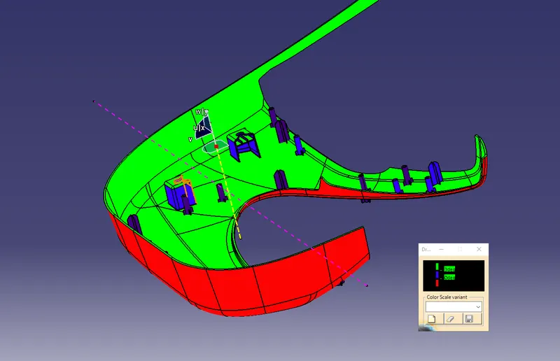 MAIN TOOLING AXIS
By applying drafting analysis at 3 Deg, we can see must bodies are been cleared. As Green set at 3 degree, blues is Zero and less than Zero it is red colored.
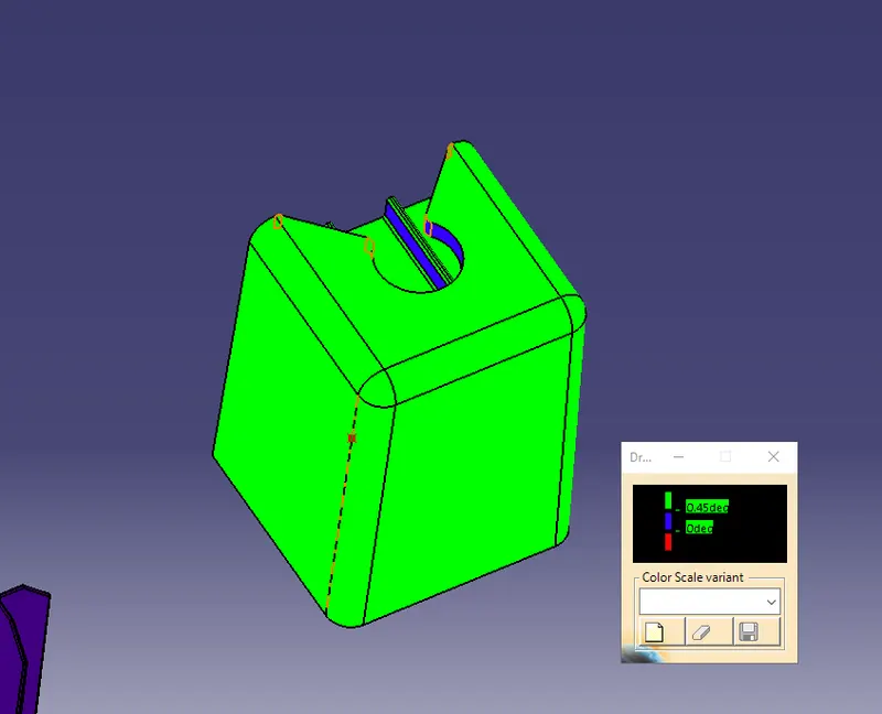
For the engineering features the draft angel is chosen as 0.5 deg as per bellow:
 TREE STRUCTURE
5-PUSH PIN
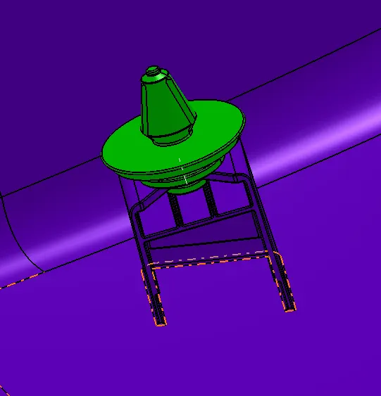
As I have created two Dog Houses for this part assembly, i need to inport two Push pins.
Both are assembled correctly as shown:
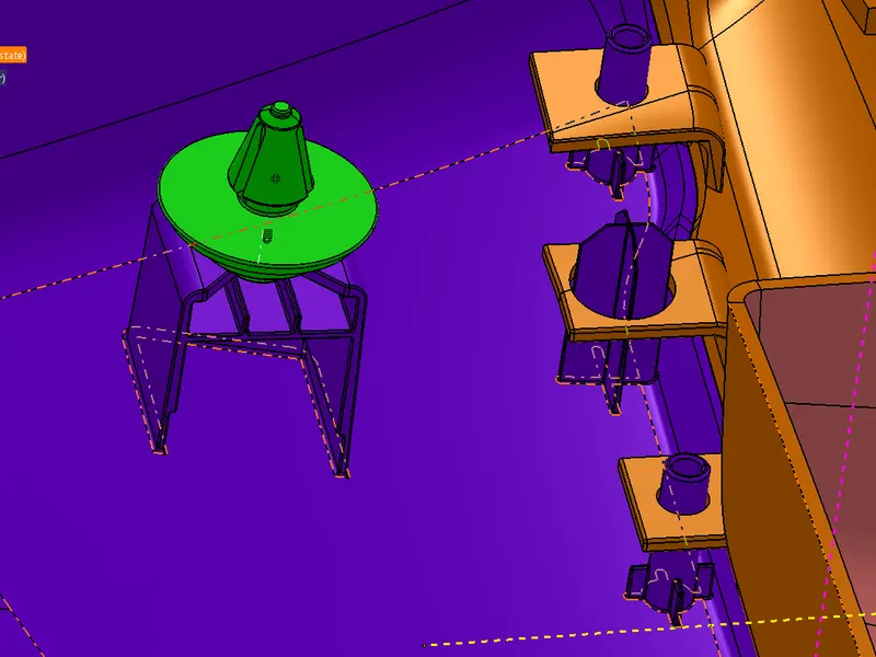
FINAL DOOR TRIM ASSEMBLY
GIVEN CAT FILE
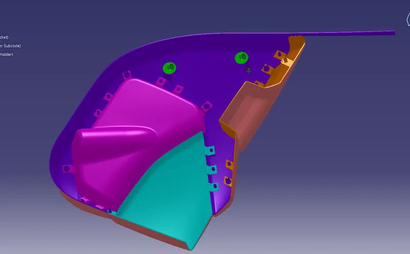
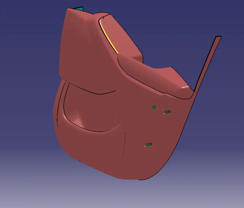
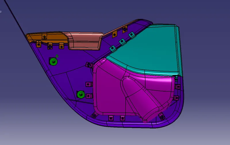
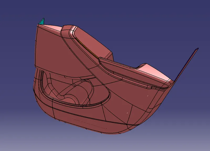
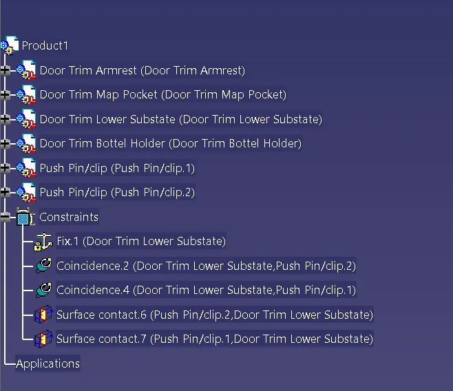
TREE STRUCTURE WITH CONSTRAINTS FOR FINAL PART ASSEMBLY.
Cat.part files
Cat.product
PPt is attached