Week 12- Final project
Final Project:
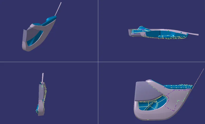
Aim: To create a door interior part from the inputs of Class A Surface along with master section by following the design rule, Using CATIA V5 Software to make this design.
Objective:
- Draft analysis for given class A surface.
- Create B and C Surface with help of A surface.
- Need to use Closure surface feature and have to make solid body.
- Draft analysis for the solid body.
- To create mounting feature as per the design guideline in the industry and with master section.
- Heat stakes need to create for door interior attachment.
- Creating of parting lines and check tooling feasibility.
-
Introduction:
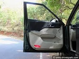
Door panels serve as an interface between the interior of the car and the inner workings of the door, and between vehicle occupants and the door. They are expected to meet a variety of design specifications regarding safety, aesthetics, and functionality. In addition, they are expected to continue the material theme of the dashboard and pillars while concealing intricate electrical and mechanical components for operating locks, windows, and other features.
Steps:
Given below is the procedure to create a new plastic component from given class A surface .
1) Creation of tooling axis.
2) Creation of class b surface.
3) Creation of class C surface.
4) Creation of closed body.
5) Adding engineering features.
6) Draft Analysis.
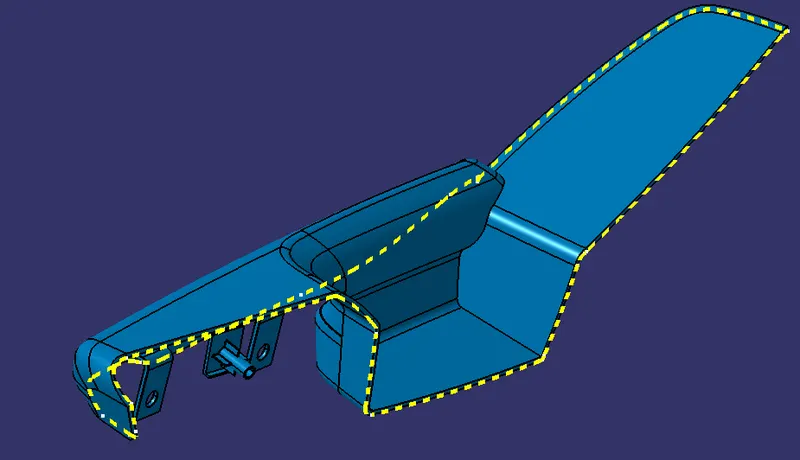
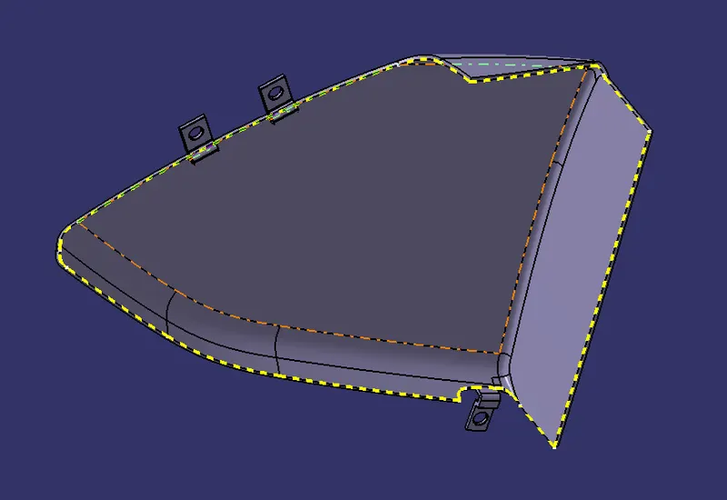
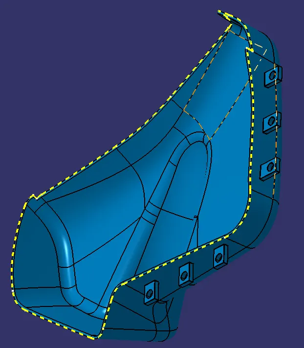
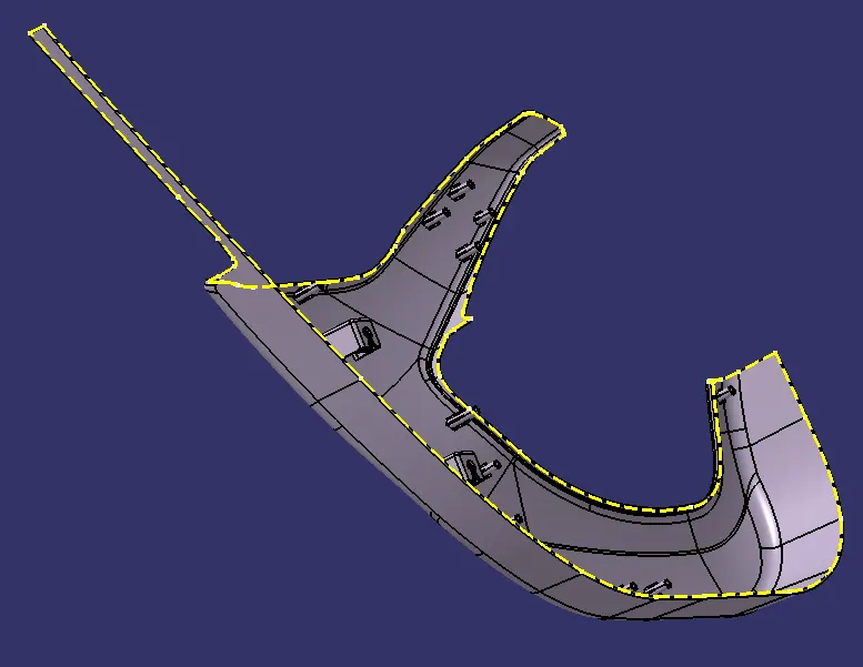
7) Creating Parting Line.
8) Assembling bodies.
9) Applying material.
10) Measuring Weight.
The main components of interior door panel of a car consists of the following parts .
1) Arm rest.
2) Map pocket.
3) Bottle Holder.
4) Upper substrate (Not given in the current model).
5) Lower substrate.
Tooling Axis.
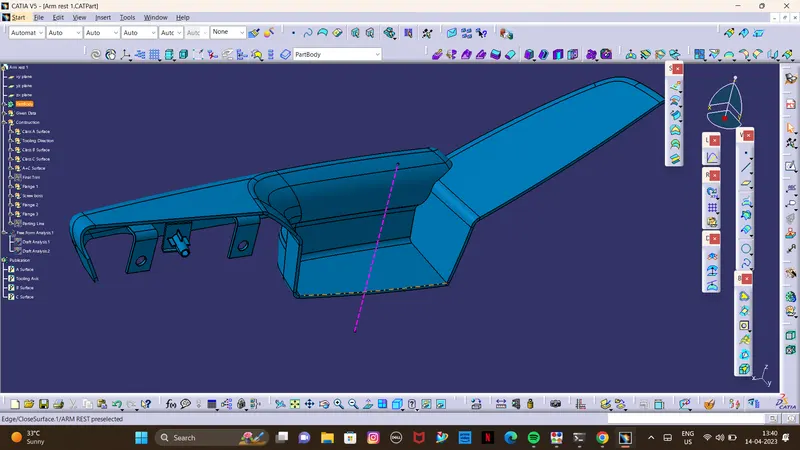
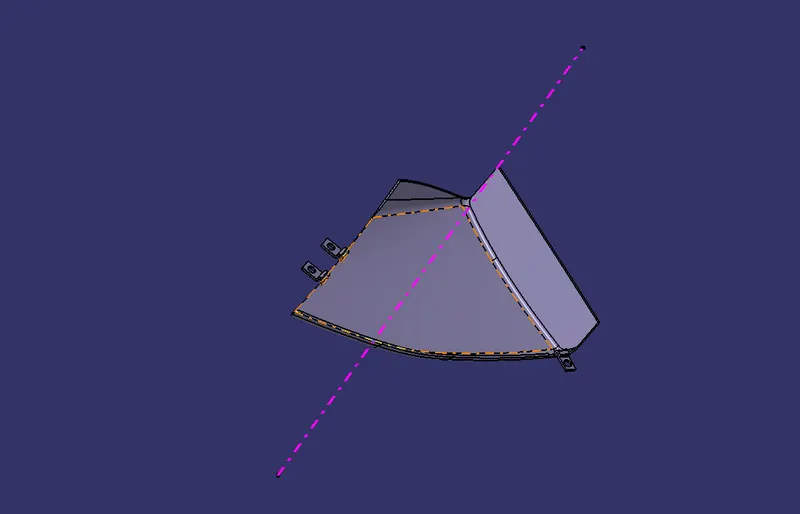
Tooling axis is the direction in which a core or cavity of mold opens. This Axis is very important to determine the orientation of the component in mold, core and cavity design as well as to run the draft analysis of the component.
1) Arm rest.
2) Map pocket.
3) Bottle Holder.
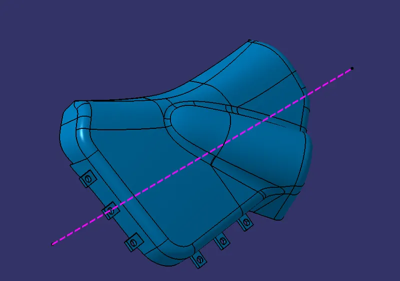
4) Lower substrate.
Class B Surface.
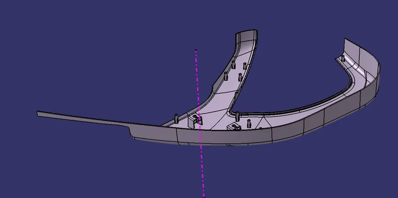
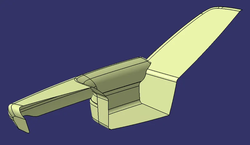
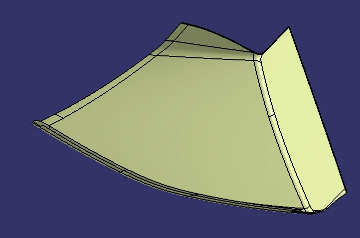
The thickness of the component as 2.5mm. Now we need to create a B surface which will be similar to the A surface at an offset value of 2.5mm. there are some discontinuities happened while offsetting the CLASS A surface so I repaired it to form a closed boundary by using the multiple extract, extrapolate, multisection and trim surface commands and tools.
1) Arm rest.
2) Map pocket.
3) Bottle Holder.
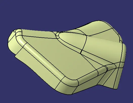
4) Lower substrate.
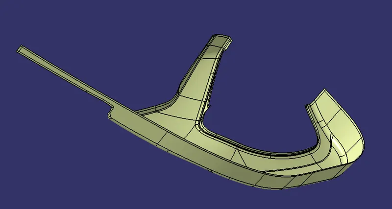
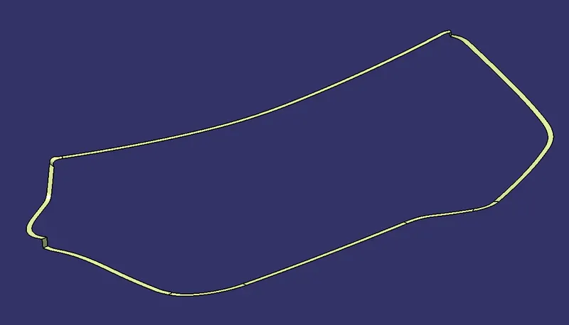
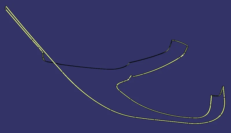
Class C Surface.
C surface is created with help of A-Surface by using the Sweep(with reference surface) and Boundary command separately, finally joined together to get the final C surface.
1) Arm rest.
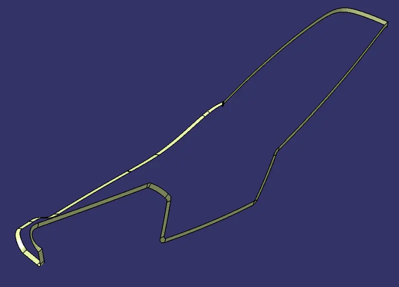
2) Map pocket.
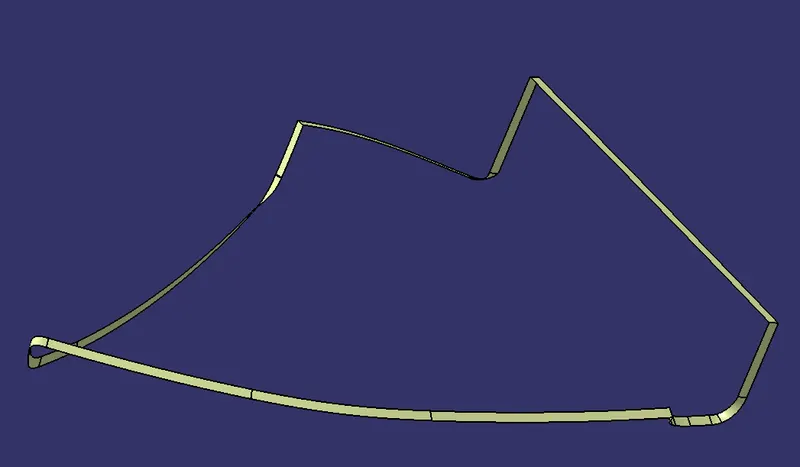
3) Bottle Holder.
4) Lower substrate.
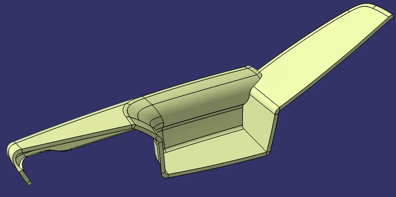
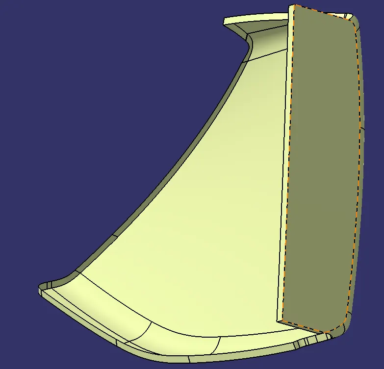
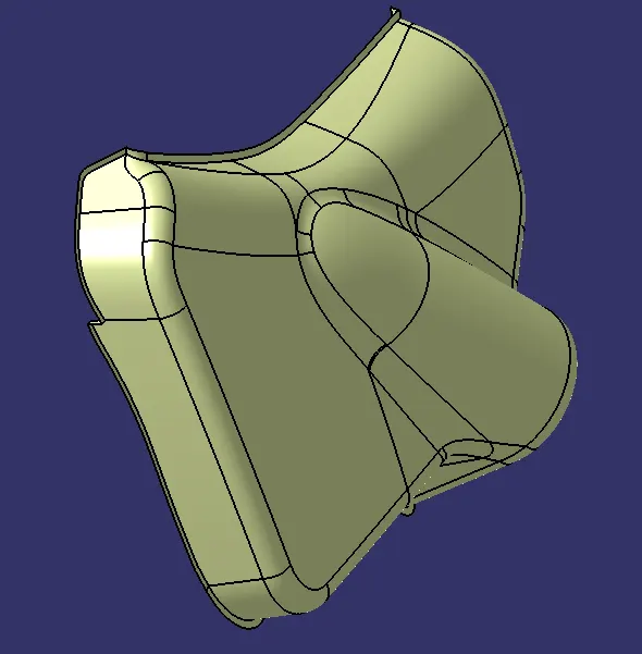
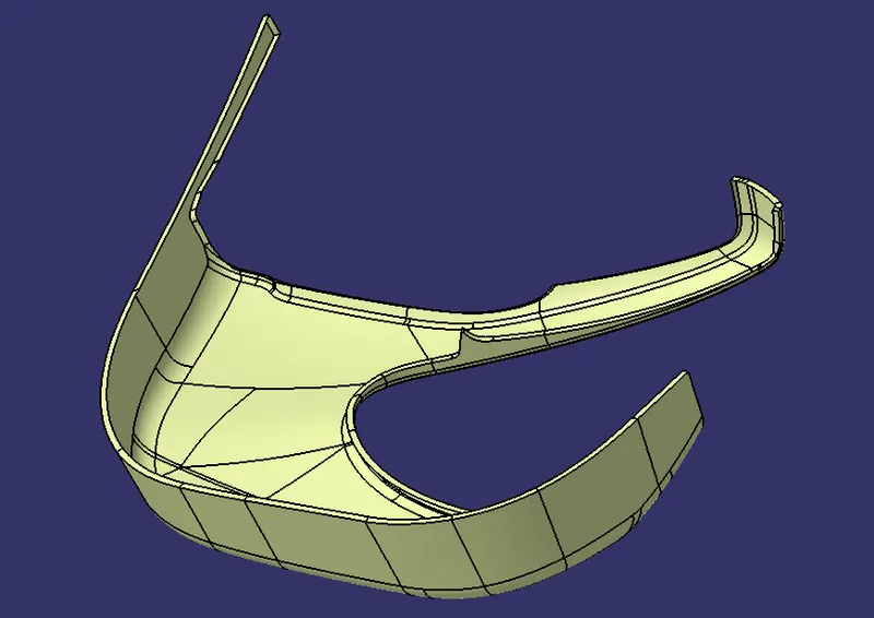
Joining of Class A & C surface.
Joined the class A & C surface together with join command. after that small gap formed, solved that changing the join deviation from 0.001mm to 0.003mm.
1) Arm rest.
2) Map pocket.
3) Bottle Holder.
4) Lower substrate.
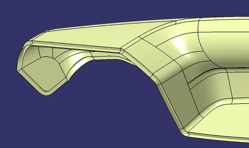
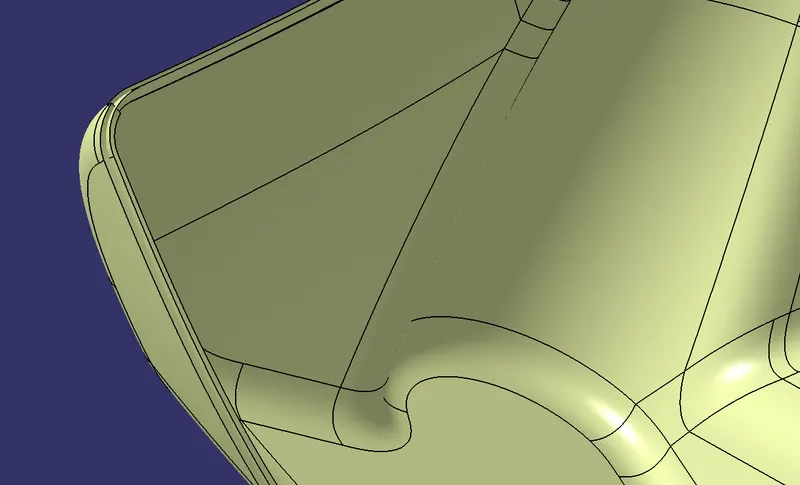
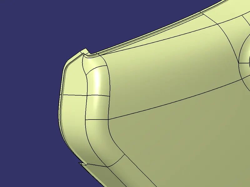
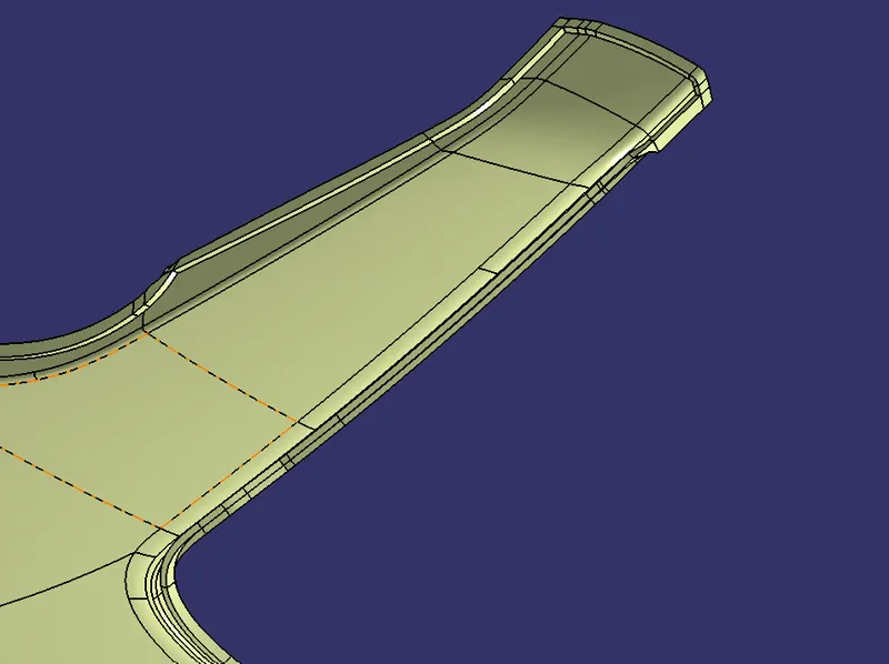
Joining Class B with (A+C) Surface.
after that I trim out the joined A and C surface to class B surface to get the final object.
1) Arm rest.
2) Map pocket.
3) Bottle Holder.
4) Lower substrate.
ATTACHMENT FEATURE.
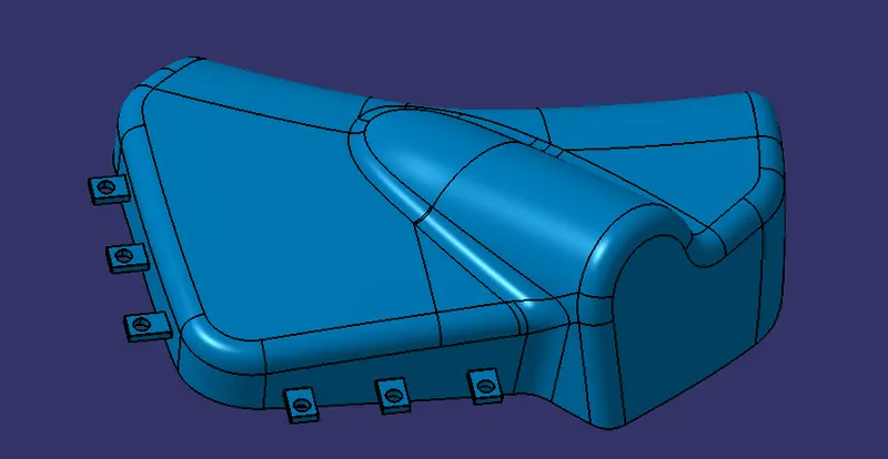
Flange creation.
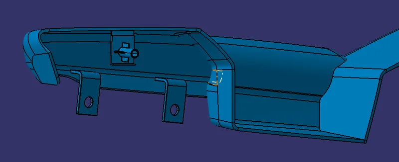
Procedure to create flanges and heat stakes for every part, from given master sections. Use multiple extract to obtain required guide curve and sweep profile for flange top surface. Use sweep option to create a surface from below and top obtained multiple extracts. Use extrapolate to extend the surface according to master section and close them to create a solid body in a new body. Create holes and flat surfaces for heat stake. This way all flanges have to create. In some areas if master secion is not given and flanges are required for those areas then create flanges without master section maintaining engineering standards.
1) Arm rest.
2) Map pocket.
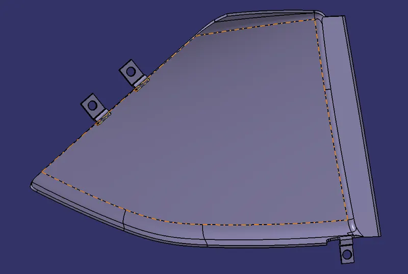
3) Bottle Holder.
Heat Stake.
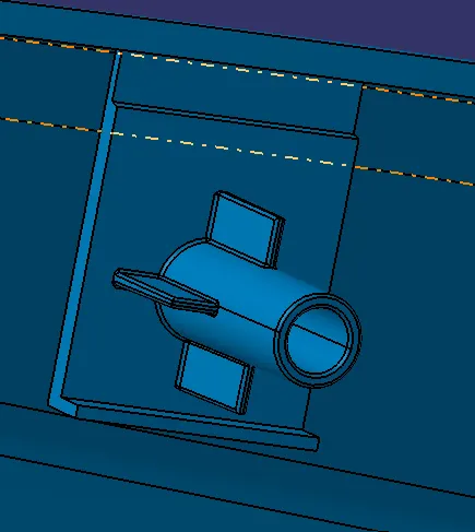
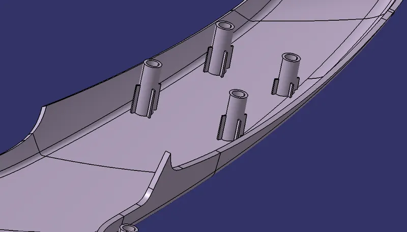
Heat stake was created from padding a sketch created from a point obtained from master section.
Procedure to create ribs on Heat stakes
- Create a sketch with center as centre of heat stake inner circle .
- Use pad option to create solid body
- Use boolean opetaion union trim to obtian required ribs.
give draft with proper angle. Then copy and pest the solid body with require amount and using 'translation' command place them in right position.
1) Arm rest.
2) Lower substrate.
Dog House.
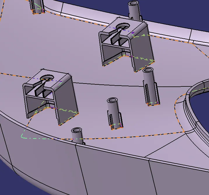
We need to create dog house to attach push clip on lower substraits. Make sure that maintain some space in front of dog house to move and adjust side core easily.
procedure to create dog house
- Create a point on required location and a plane from it . Create a sketch with base sketch for dog house.
- Use sweep tool to create a surface using this profile and draft direction at a draft angle of 1.5 degrees.
- Use extrapolate and extrude option to create required surfaces and use trim and split to obtain the outer body of dog house.
- Create a new body and name it as dog house 1 . Use thick surface option to create a solid of required thickness.
- Translate the dog house to required height using translate option and use thick coomand to extend the base surface to intersect the lower substrate.
- Extract the inner base edge and create a surface to get the required base profile . Use thick surface to create a solid and use boolean operation to remove it from the base of dog house.
- To create top profile for attachment of push pins , create a stech , extrude it and split it from the solid using split option.
- To create a base for push pins to rest , create another sketch extrude and off set it . Create solids feom it using thick surface option.
- Use boolean operation union trim to obtain required design.
1) Lower substrate.
Parting Line.
A parting line, in industrial casting of molds, is the border line in which draft angles change direction. One can check the parting line in the mould or product which divides the two half, i.e; the core and the cavity of a molded part. It is sometimes a starting point for the mold parting surface.
The parting line of a die cast component represents where the two different sides of the mold come together. This line often (but not always) marks the border between the inside and outside of the part.
1) Arm rest.
2) Map pocket.
3) Bottle Holder.
4) Lower substrate.
DRAFT ANALYSIS.
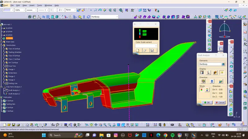
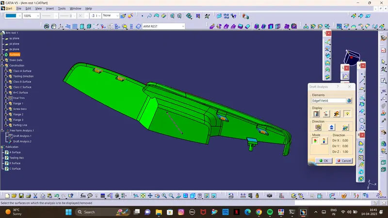
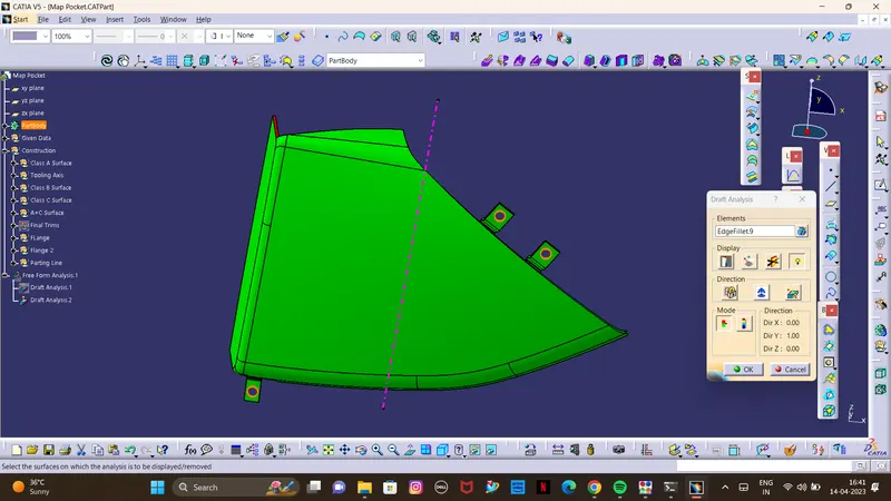
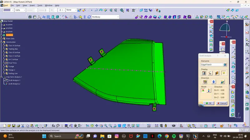
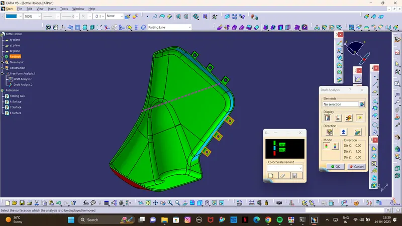
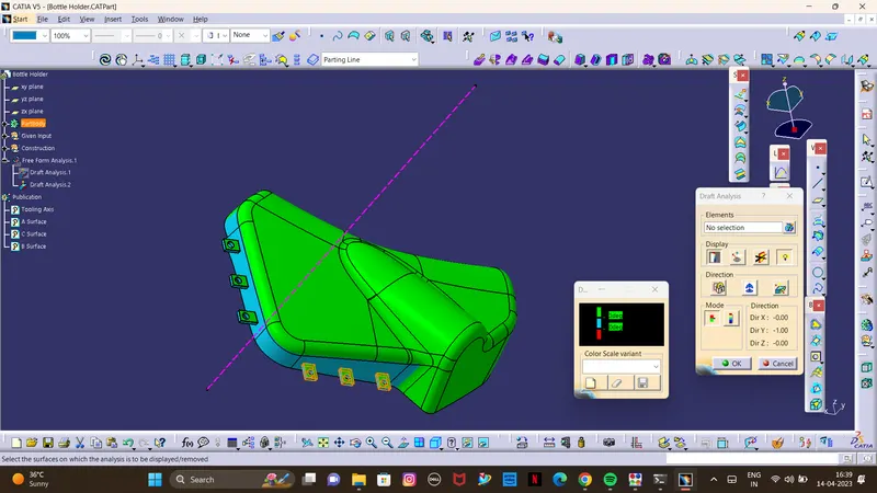
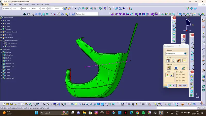
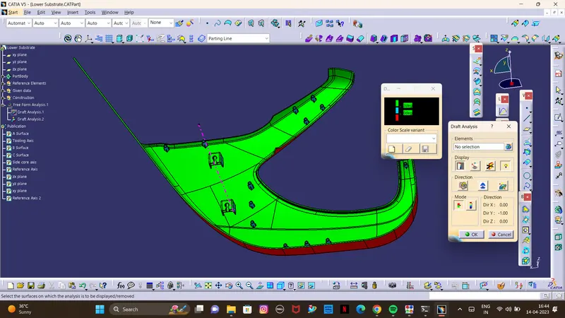
The Draft Analysis allows the user to easily analyze a part for proper draft angle. A Draft Angle describes the amount of taper for molded or cast parts perpendicular to the parting line.We have 2 modes on the draft analysis Quick & Full analysis respectively.Under the Display option we have Show are hidden the Color Scale, Analysis under the running point, No Highlight representation & Light effect.Under the Direction option we have lock or unlock the direction, Compass & Invert.So According to the practical Usage there Should be 1 to 3degree of angle mostly acceptable, by considering these option we have to test our given & Final Components Draft analysis.
1) Arm Rest.
Class A Surface.
Class B Surface.
2) Map pocket.
Class A Surface.
Class B Surface.
3) Bottle Holder
Class A Surface.
Class B Surface.
4) Lower Substrate.
Class A Surface.
Class B Surface.
Heat Stakes.
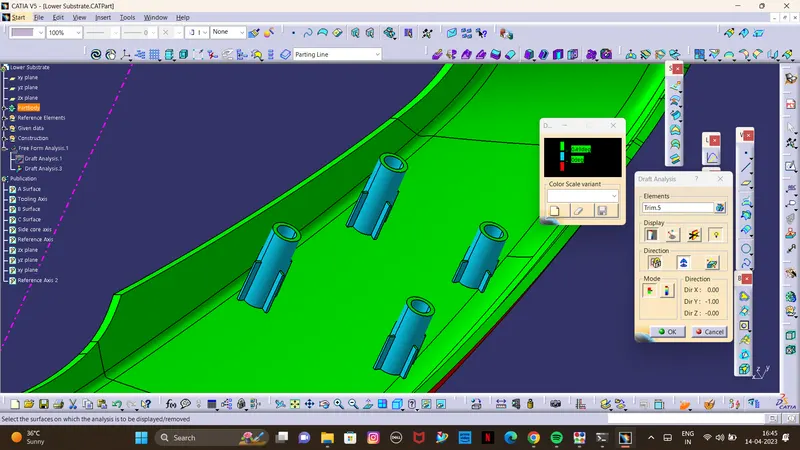
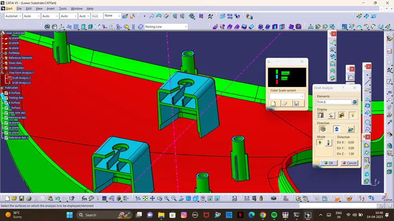
Dog House with Main tooling axis.
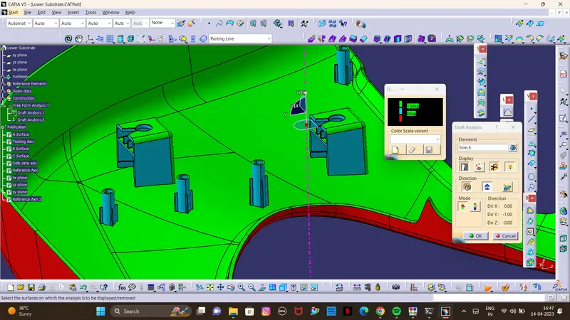
Dog House with Side Core axis.
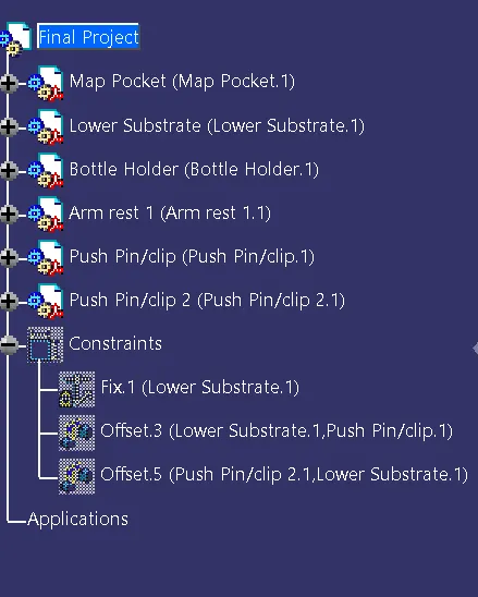
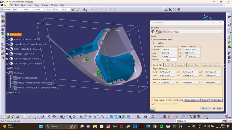
ASSEMBLY.
Part Tree.
Applied Plastic Material to the Product and Weight Measurement.
FINAL PRODUCT.
Front View.
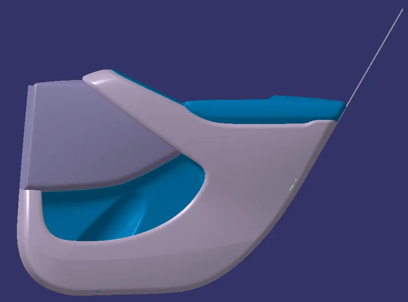
Back View.
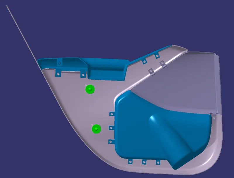
Multi view.