Week 12 Challenge
Aim:
To create a proper ejection system with ejector pins and plates, runner and gate system, air vents and cooling channels for the mold.
Procedure:
In the previous challenges we have created the mold blocks, inserts, sliders for the plastic knob component.
in order to create the ejector pins, create a sketch on the top surface of the cavity block as shown below,
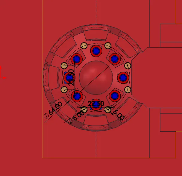
Create a hole with cut extrude command using above sketch.
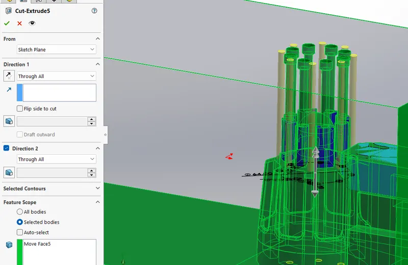
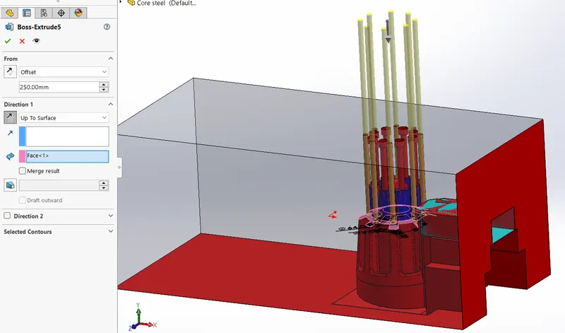
Create ejector pins of 6mm diameter using boss extrude command.
Select offset of about 250mm from the bottom surface.
Create a clearance hole of aprrox. 6.96mm diameter.
Next we wil be creating the ejector plates. Before that we will be creating the head portion of the ejector pins.
Draw a cirlces on the top surface of the pin of diameter 10mm cut partially for locking purpose and extrude for about 3mm upward.
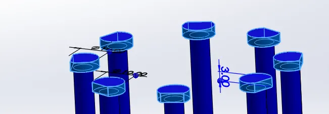
Draw a rectangle on the top surface of the pin head and extrude for about 10mm downward and anandeselect merge entities.
The 2 side of the rectangle sectionhould at an offset distance of 45mm from the side of the mold block inwards direction.
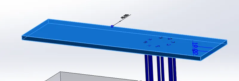
Now create a slot for the pin head in the rectangular plate.
Create another rectangular plate of same dimensions as pe the previous rectangle and extrude for 15mm verticallly upward direction.
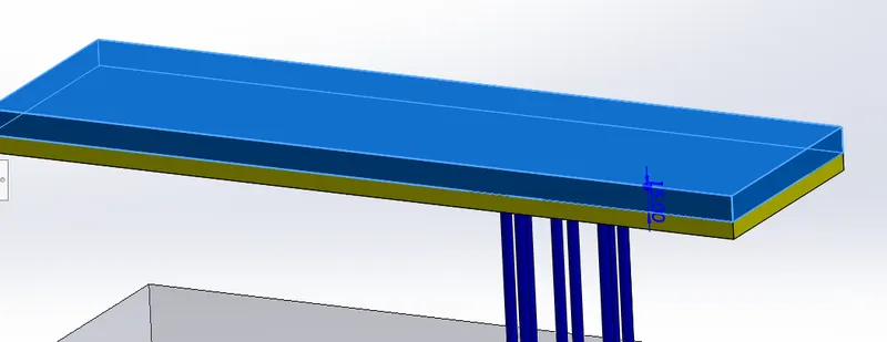
Next we have to create a sprue and runner under the cavity block for the passage of molten plastic in the block at desired locations.
From the molding nozzle, the sprue leads into the runner, which then directs the melt into the mold cavity through the gate. At the end of the runner is the gate leading into the mold cavity. The gate leaves a surface blemish on the part. It is small and designed to freeze before the part, runner, or sprue freeze.
From the molding nozzle, the sprue leads into the runner, which then directs the melt into the mold cavity through the gate. At the end of the runner is the gate leading into the mold cavity. The gate leaves a surface blemish on the part. It is small and designed to freeze before the part, runner, or sprue freeze.
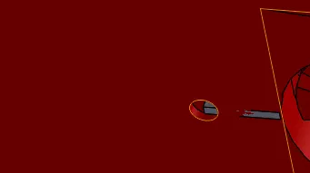
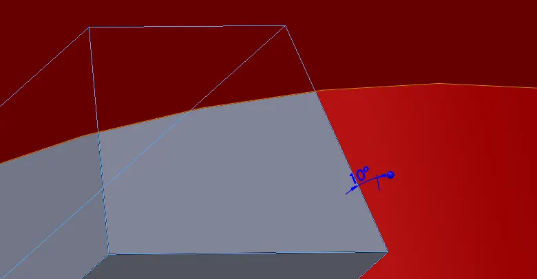
The draft angle angle for the runner has tp be 10 degrees.
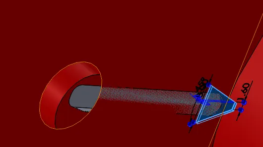
Air wents has to be created for the following reason,
Air vents is a small channel provided in the mold block for easy escape of air. When the mold block closes after one cycle of molding there will be some amount of air gap in the mold. If we do not provide an escape then air will be present in the mold block and it will lead to defects in molded components. There fore we create air vents.
The gap of arounf 0.02mm is provide for thr core block.
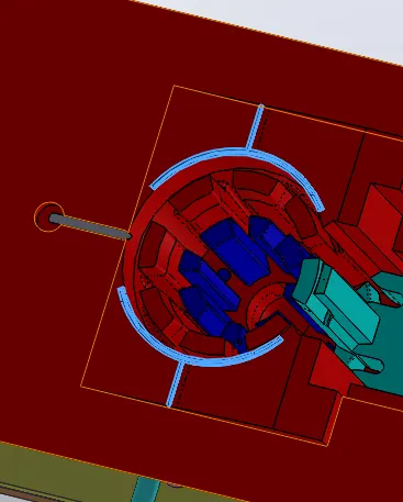
We create cooling channels by keeping in mind that we should provide uniform cooling throughout the mold so that defects such as warpage do not occur.
The diameter and lecght of the hole is described in below image,
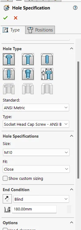
Apropriate colouring to the cooling channels are provided.
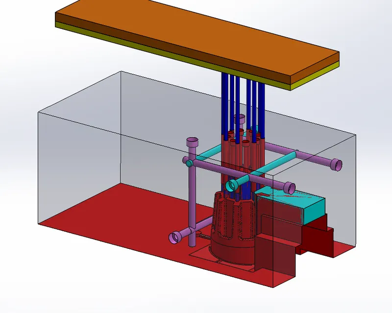
Complete assembly:
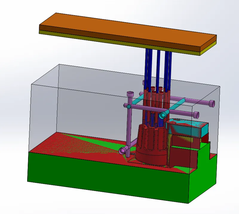
Conclusion:
Hence all the components such as mold blocks, inserts, sliders, ejector pins, plates, runner and gate system, bolts are create for the Plastic knob part component.