Week 11 - Project - A pillar Design with Master Section
OBJECTIVE
To create A Pillar with master section provided as Class A Surface and Dog House to be created on Class B Surface. Perform draft analysis of the A Pillar with Dog House along with Tooling Axis.
INTRODUCTION
Car pillars are angled or vertical parts of an enclosed car's body that support the roof and reinforce the torsional rigidity of the body.
The letters (in uppercase) A, B, C, and D are used to represent each pillar:
- The A-Pillar which supports the roof at each corner of the windshield, is the pillar that faces forward on a car.
- The B-Pillar supports the roof structurally and is situated between the front and rear side windows of a car.
- The C-Pillar is the rearmost on two and four door sedans and hatchbacks.
- The D-Pillar is the rearmost pillar on larger four door vehicles such as station wagons and full-sized SUVs.
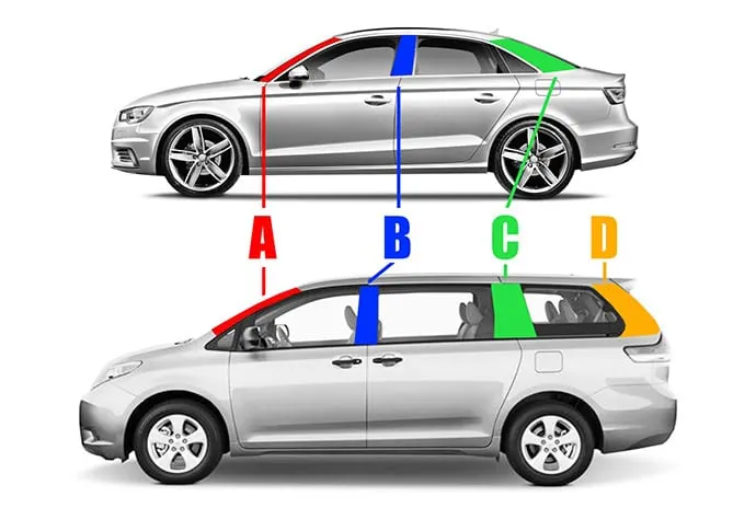
A-PILLAR
The windshield is supported from side to side by the car's primary pillar. Over time, most cars have changed the form of the window that sits between the front glass and the first side window. Airbags are added to this pillar by manufacturers to provide safety and compliance.
In the 1960s, automobile pillars were rather thin in comparison to those of today. The previous hard tops are no longer visible in the market due to safety precautions and regulations. The hardtop style is still popular, nevertheless, since many manufacturers attempt to blend it in as much as possible with the windows and give it a single chrome outside lining. It is crucial to remember that an excessively wide A-pillar may make it difficult for pedestrians visibility at cross points which might prove fatal.
Dog House
Dog house is an engineering feature used in plastic trim design and also used as supporting feature. Sometimes other engineering features like locators, screw bosses are mounted on dog house to increase the strength. While designing dog house, it should clear draft analysis so as to prevent breakage of the component during ejection from mold cavity. Dog house and other engineering features are created on Class B Surface. Dog house are made to prevent sink marks from screw bosses on Class A Surface and to address length concerns when attaching screw bosses that require assembly to other parts.
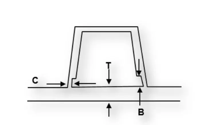
Design criteria for dog house:
- C thickness should be 40% of the main wall thickness T
- Minimum width of the dog house is 12 mm
- Height of B should be 3 to 6 mm
- Minimum draft for the dog house is 5 degrees
DESIGN METHODOLOGY
Input A Pillar Master Section
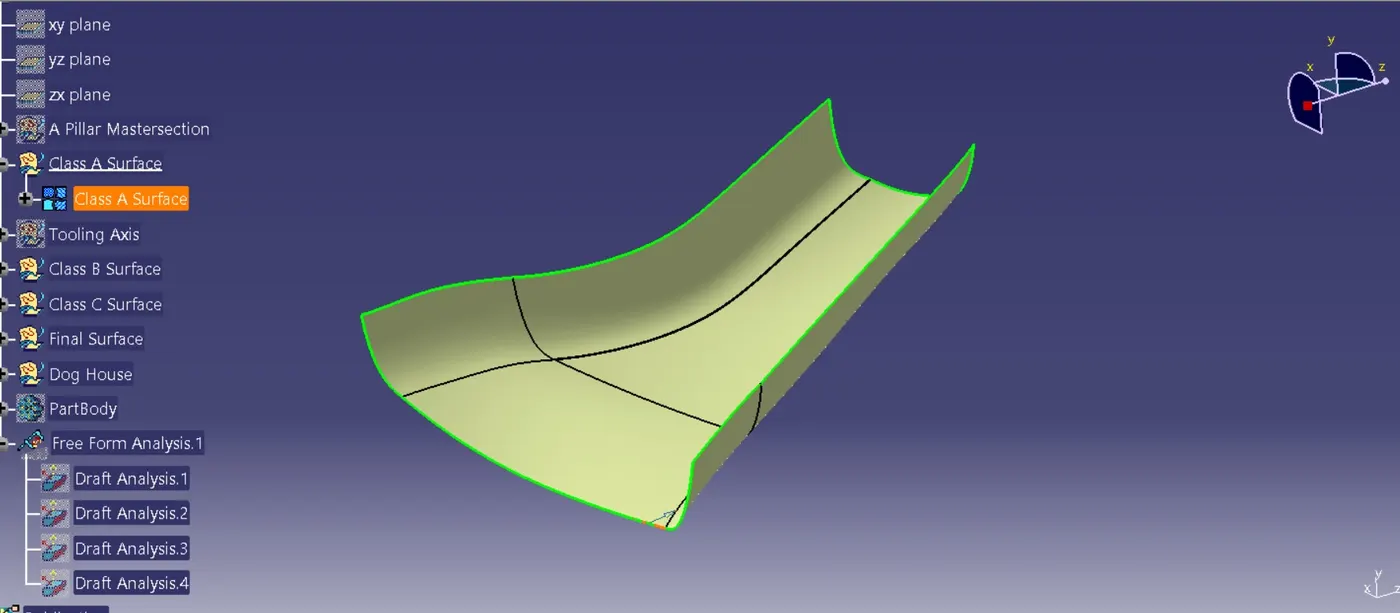
Class A Surface
Class A surface is the aesthetic part of the model, which is already created by design engineer as input Class A Surface.
Tooling Axis
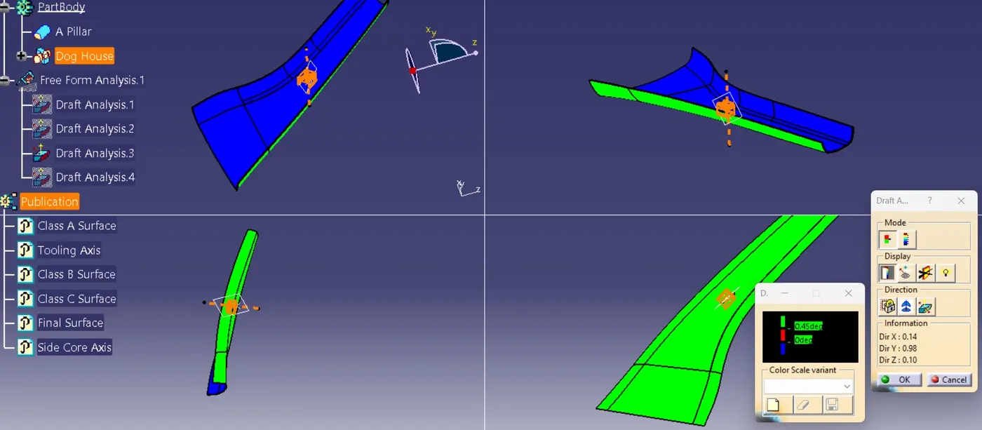
The Tooling Axis indicates the direction in which the mold separates from the casting. The mold is divided into two distinct sections: core and cavity. The Tooling Axis is created when the Core separates from the Cavity. The draft angle also determines the part's ejection from the mold. A zero draft may produce shrinkage, resulting in difficult or no ejection. As a result, for all plastic component manufacturability, the draft angle is set to 3 degrees. In most cases tooling direction could be along the surface, or by creating bisecting line from the surface profile.
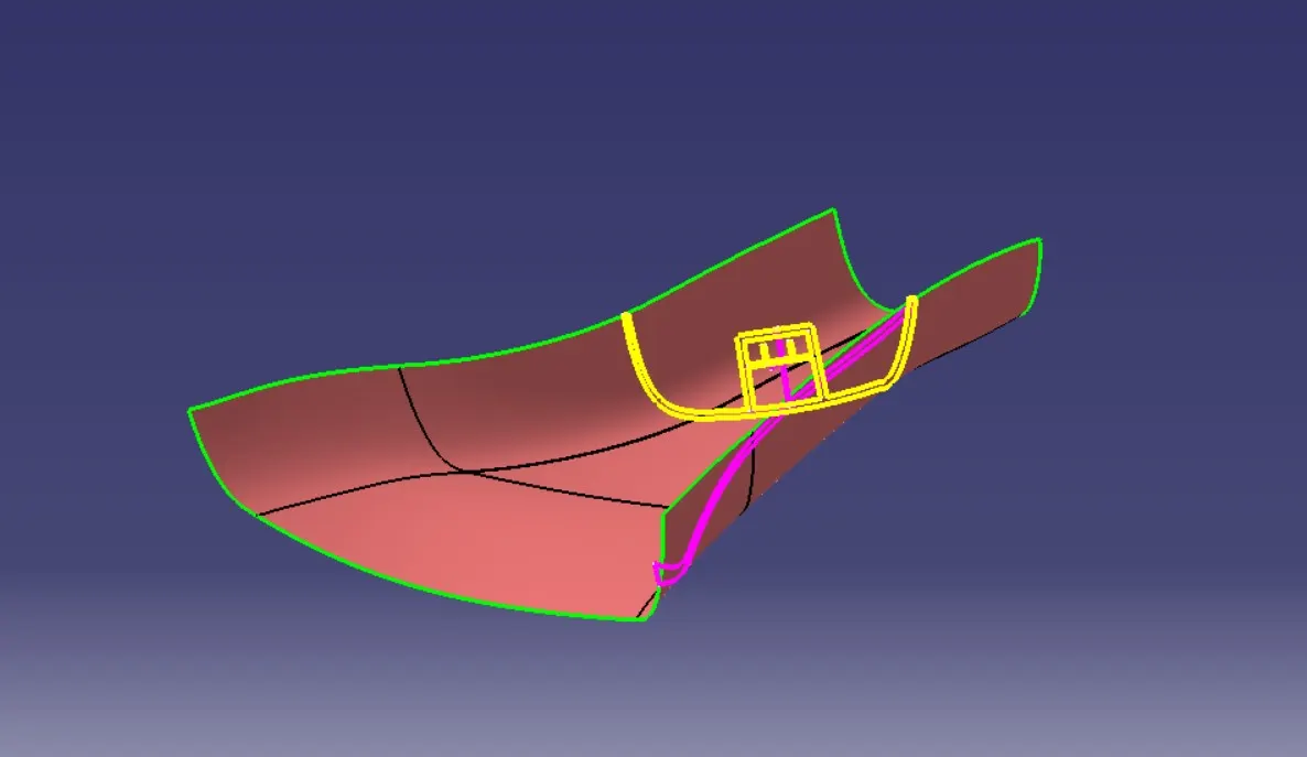
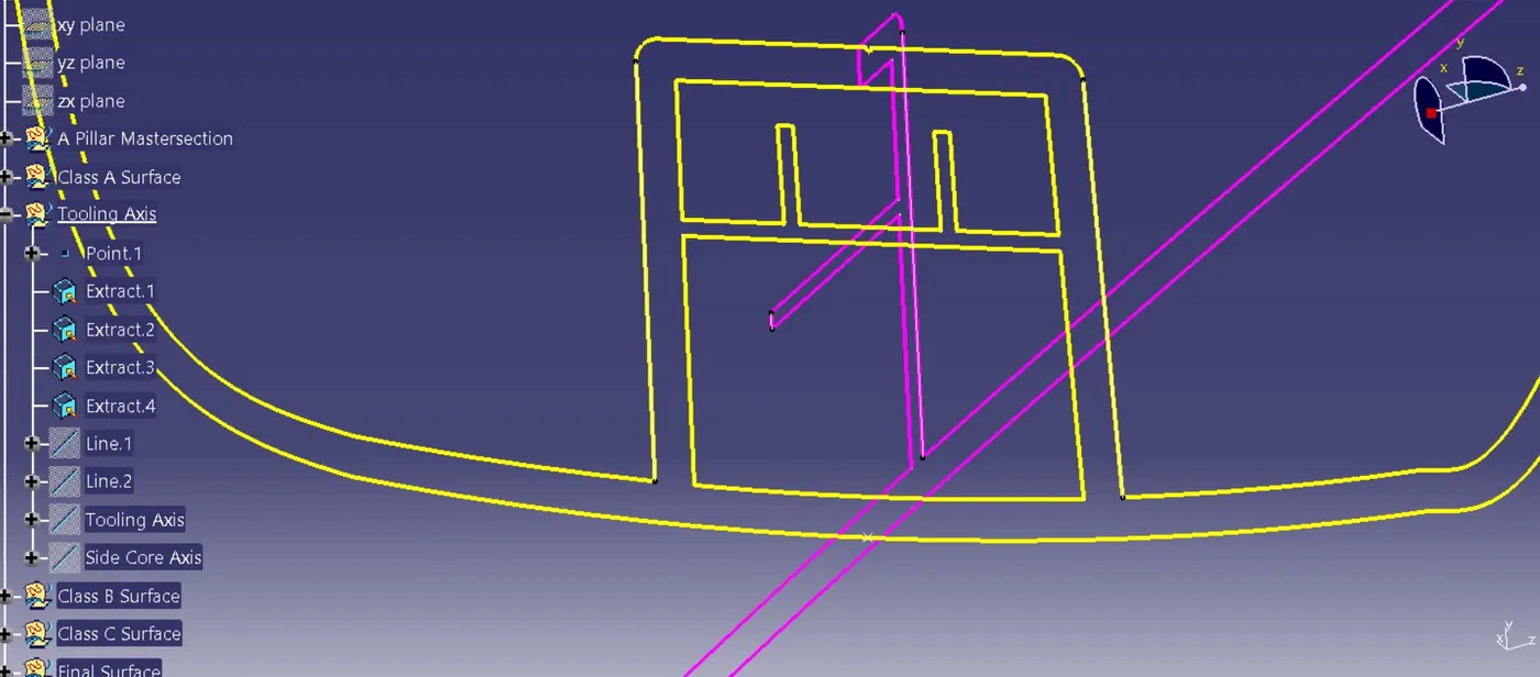
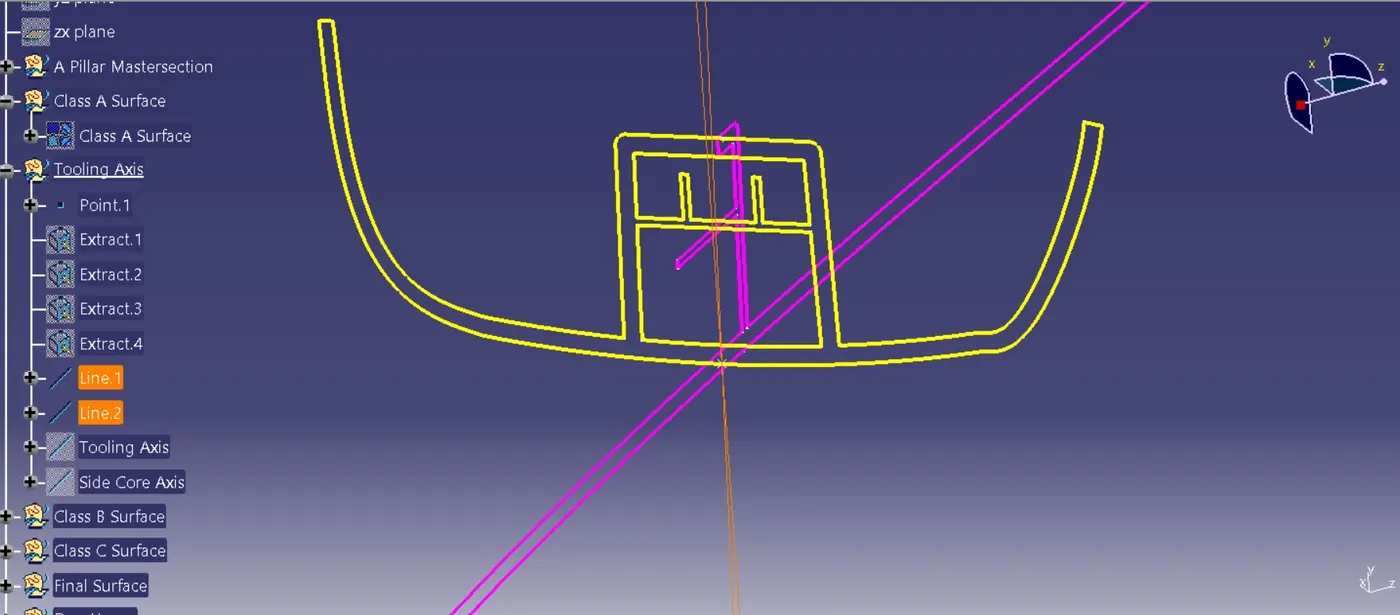
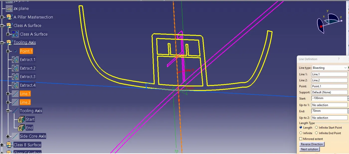
To create tooling axis for given A Pillar master section, take extracted lines from the provided intersection. Then create tooling axis using bisecting line method from the extracted lines.
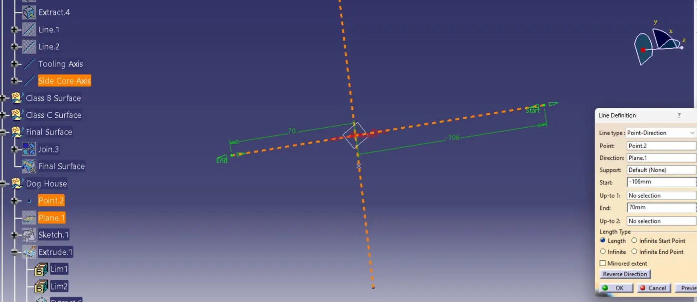
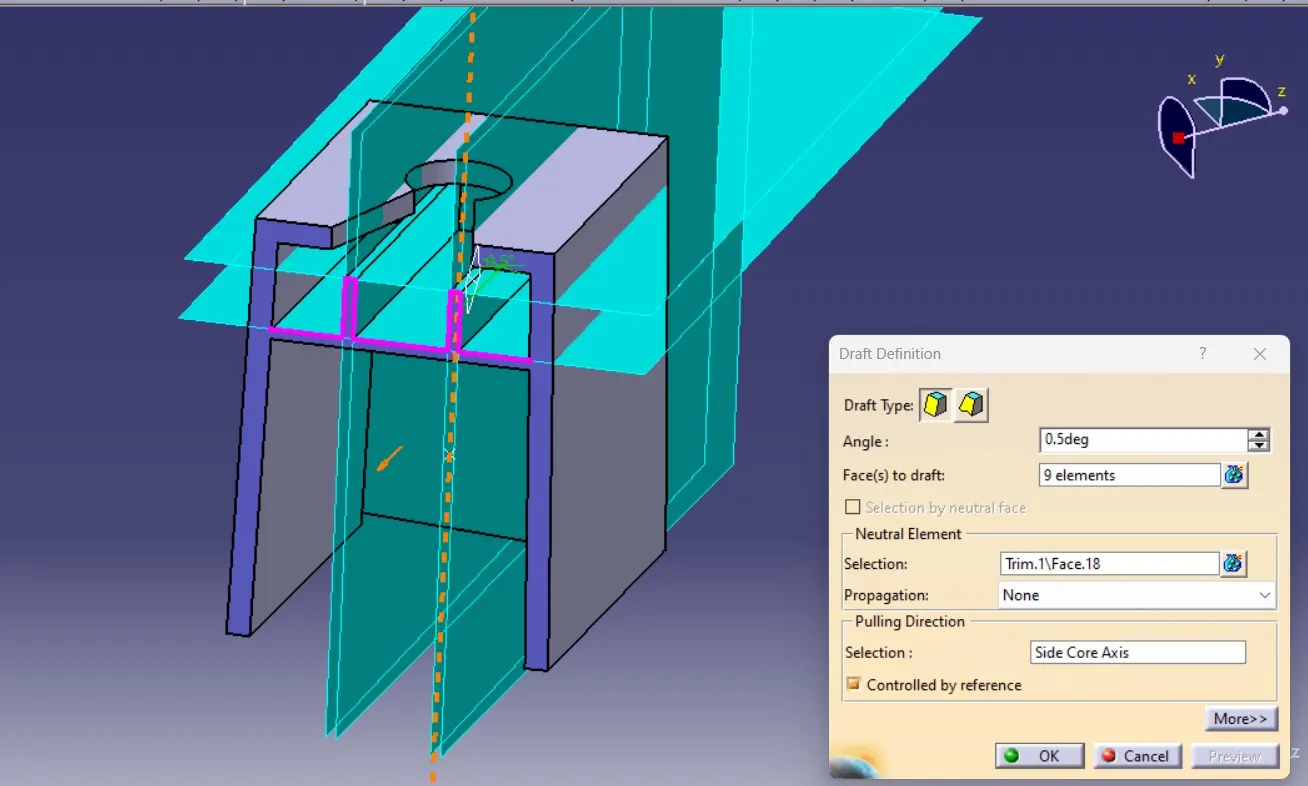
Side Core axis is created using Point and direction method from which direction is taken as plane of the dog house to be created.
Draft Analysis
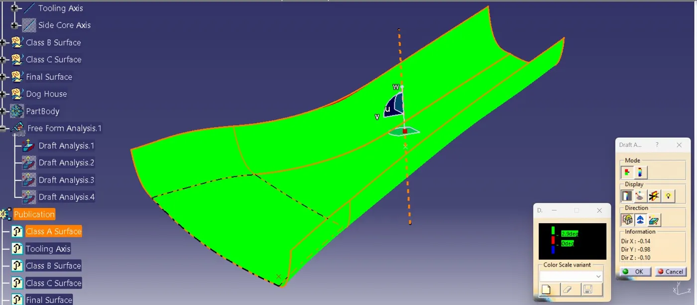
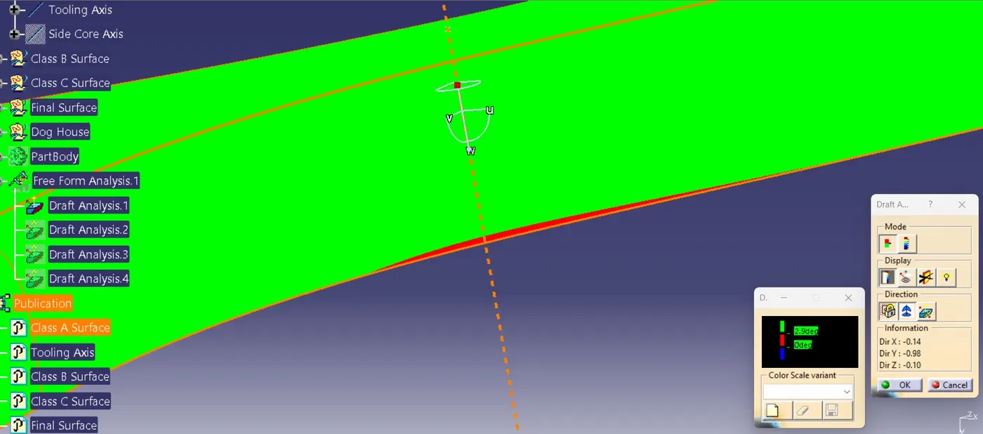
At the region of shown below the draft angle is zero degree draft but only for a small area. We can communicate this to Class A designer to modify the surface so as to clear perfect draft analysis along with the tooling axis.
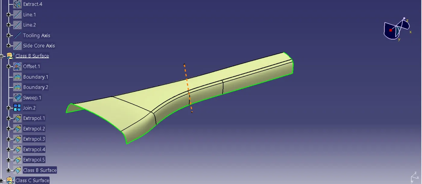
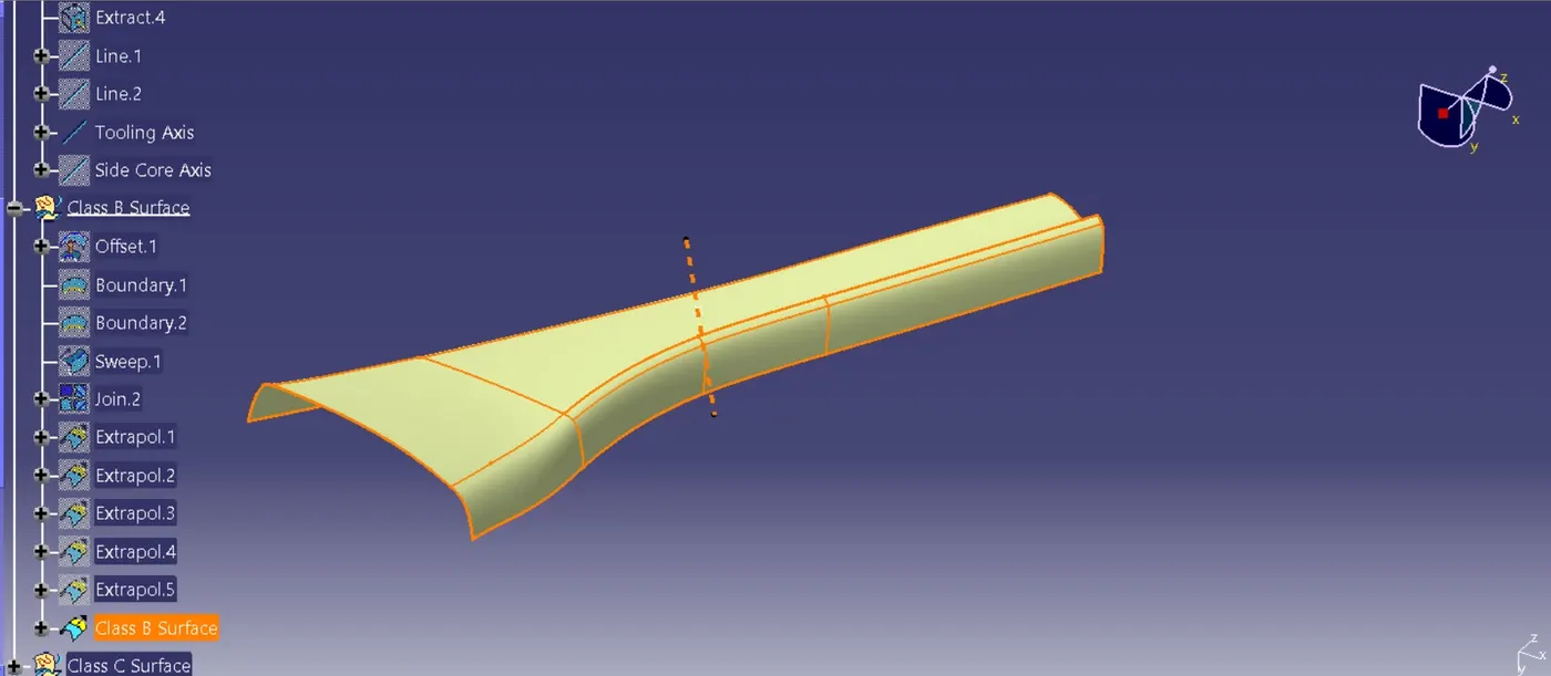
Class B Surface
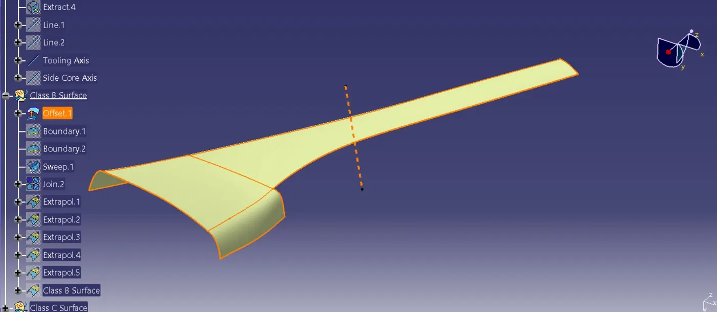
Class B Surface is created by offsetting the Class A Surface with thickness of 2.5mm.
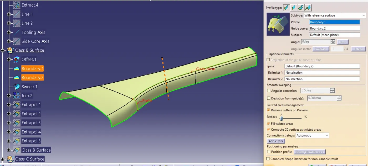
The missing surface of Class B Surface can be obtained by creating Profile and Guide curve and then using sweep method. Join both the surfaces and extrapolate outer boundary to obtain Class B Surface.
Class C Surface
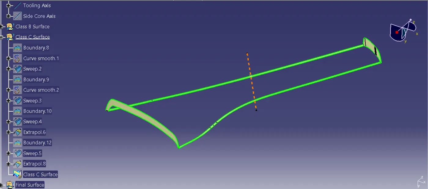
Class C Surface is the joining surface between Class A Surface and Class B Surface to obtain the solid plastic model. It is created using boundary command on Class A Surface and performing Sweep command with reference to Tooling Axis or with reference surface.
Final Surface
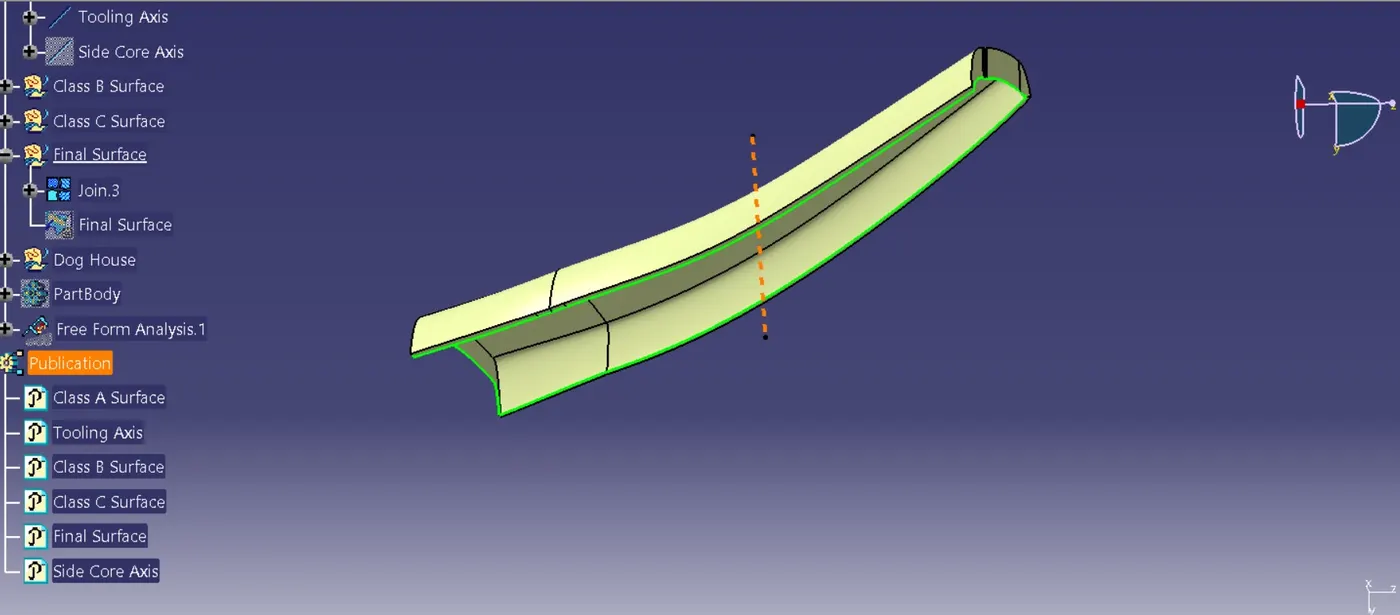
Final Surface is obtained by joining Class A Surface and Class C Surface, then using Trim command with the joined surface and Class B Surface to obtain the closed surface model.
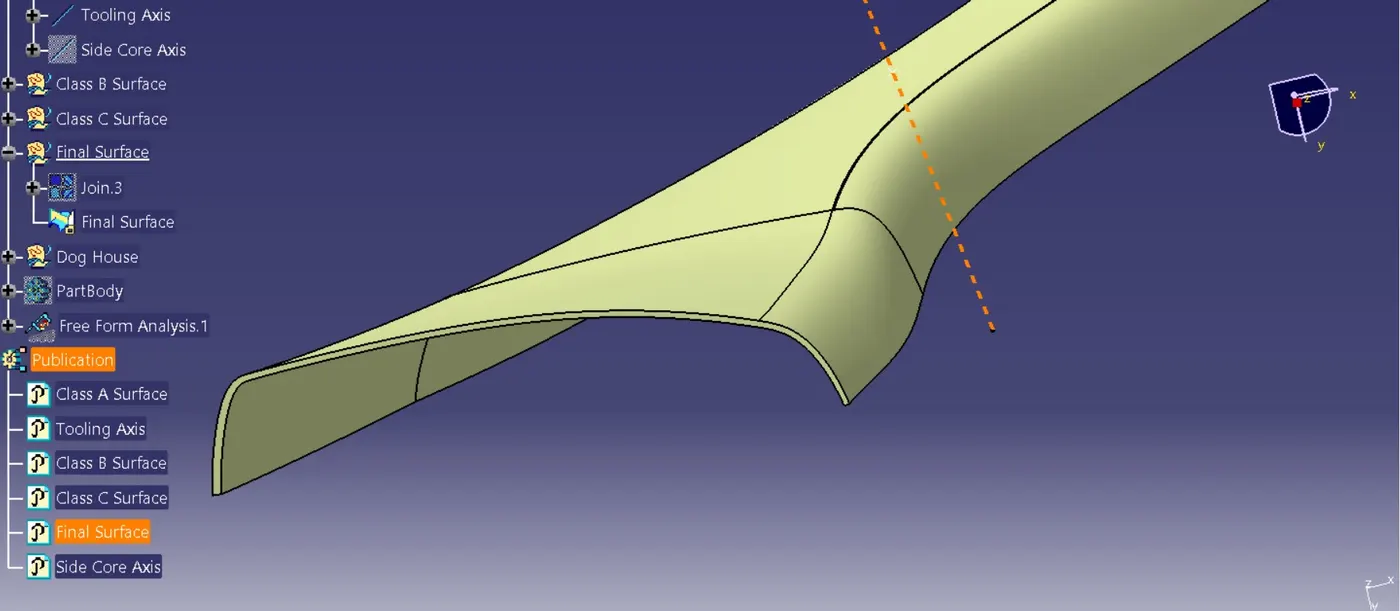
Draft Analysis
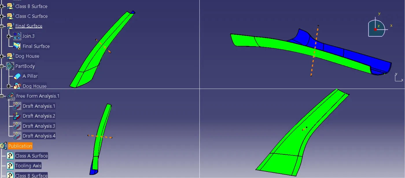
Closed Surface
For the final door handle part model, plastic model can be obtained by going to Part Workbench and using command Close Surface.
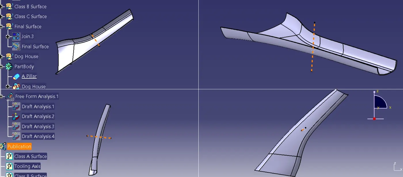
Dog House
Proposed dog house reference model:
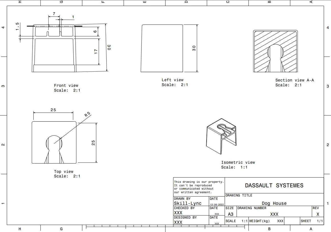
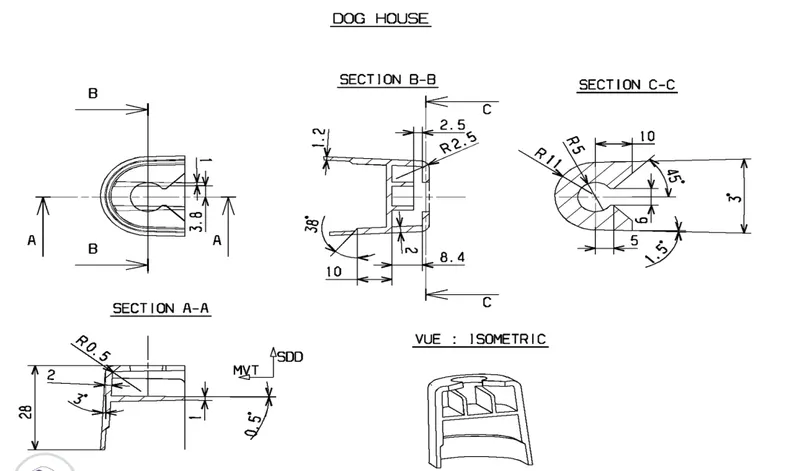
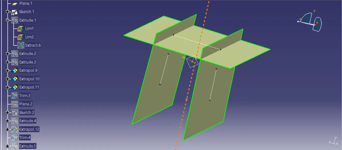
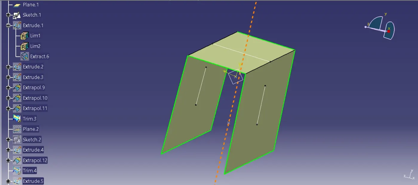
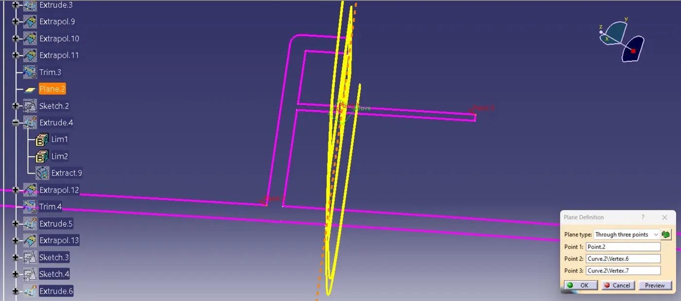
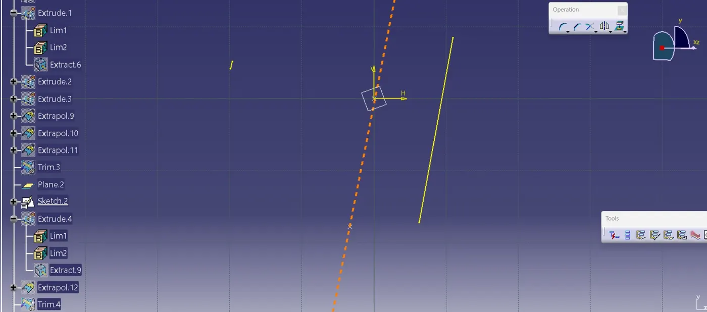
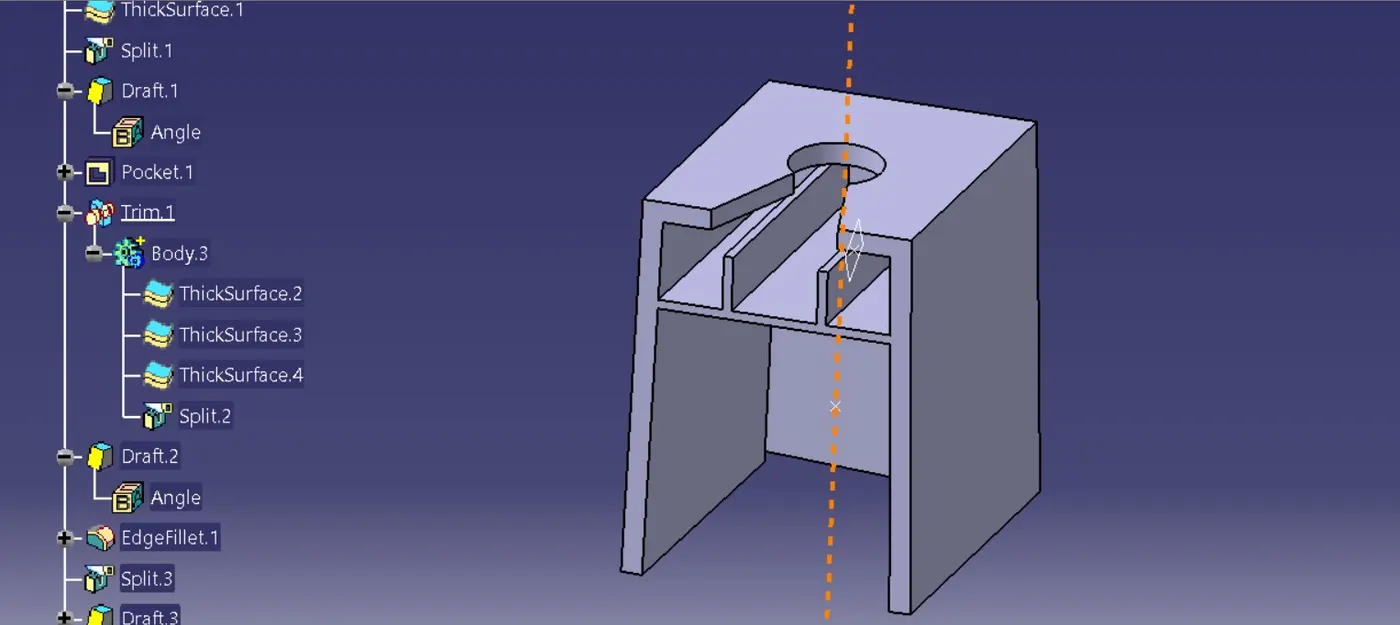
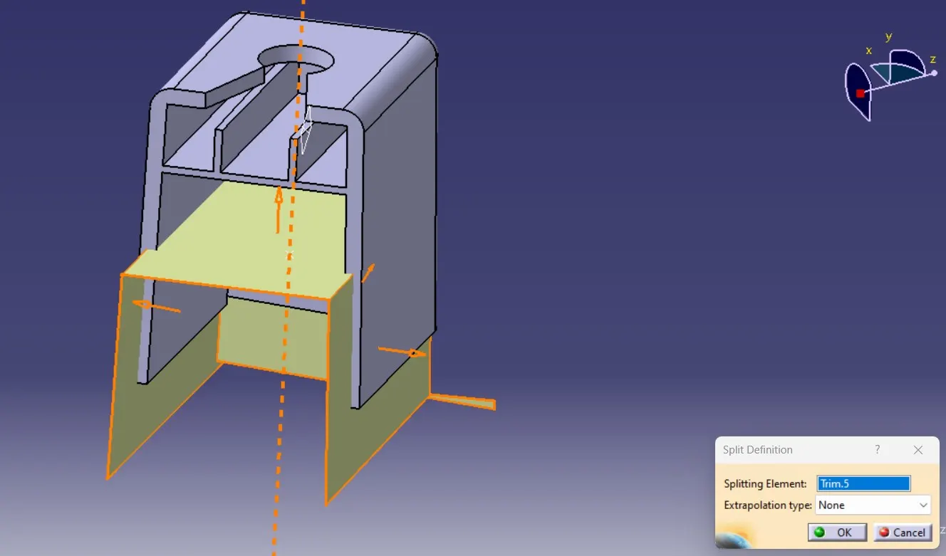
Steps involved in creating Dog house:
- Create a point and plane on the curve from given master section.
- Create a sketch from the projection lines with reference to master section, that can be extruded to create the doghouse's walls.
- Thicken the outer walls of dog house to obtain solid model.
- Provide proper draft of 0.5 degrees to walls of dog house along with side core axis.
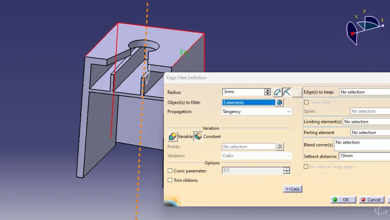
- Edge fillets of 3mm and 0.5mm are provided to obtain the final dog house.
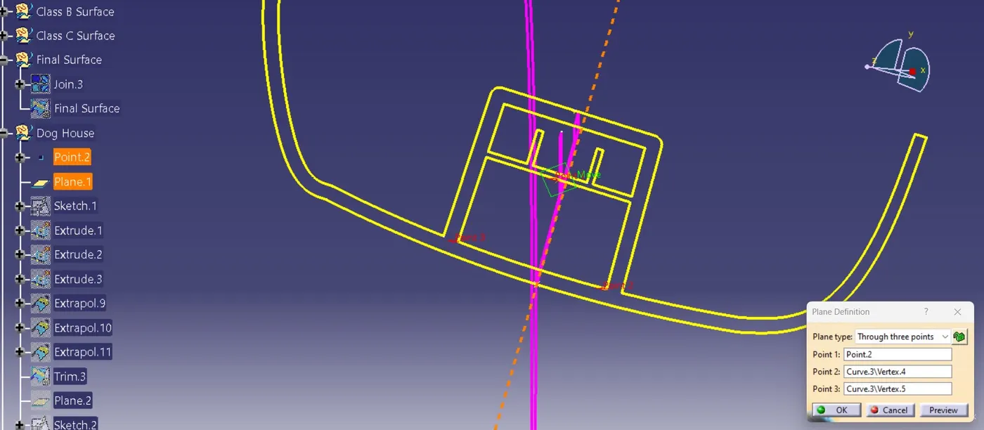
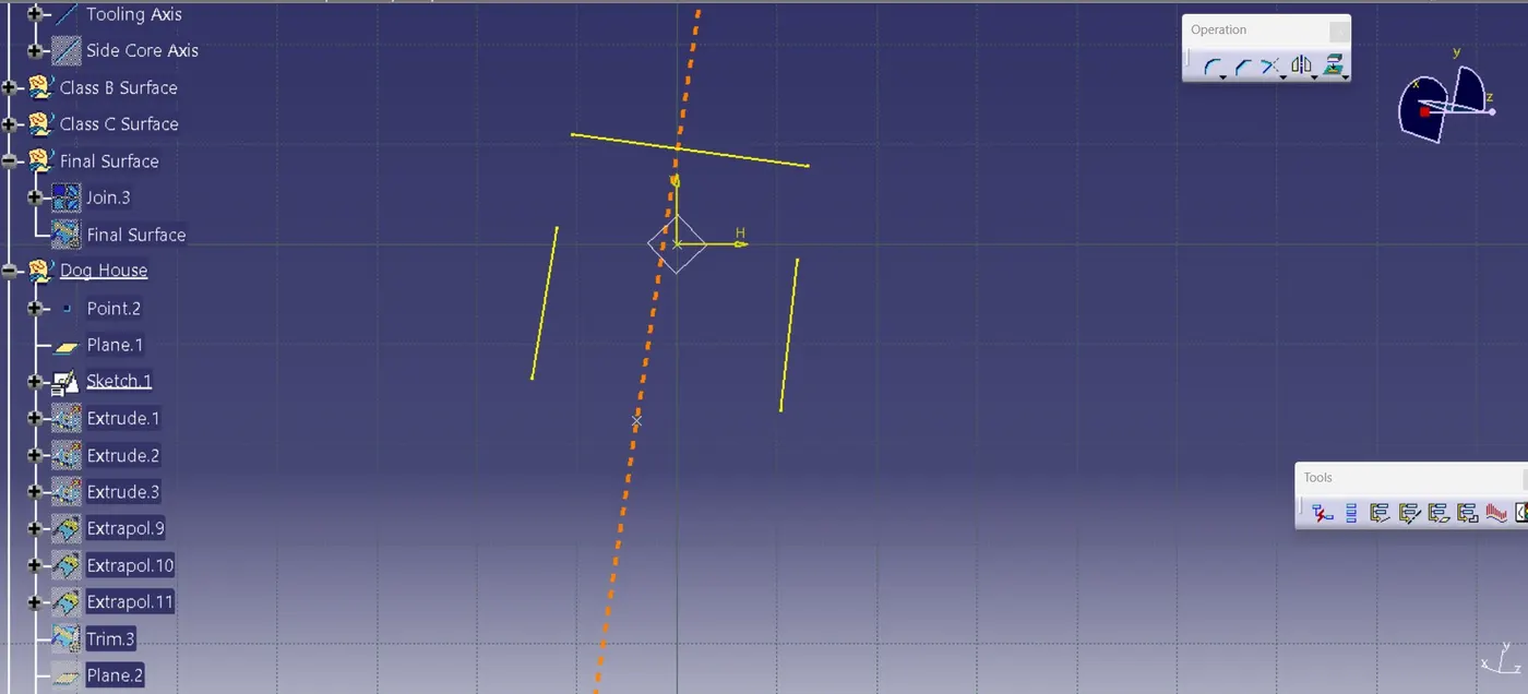
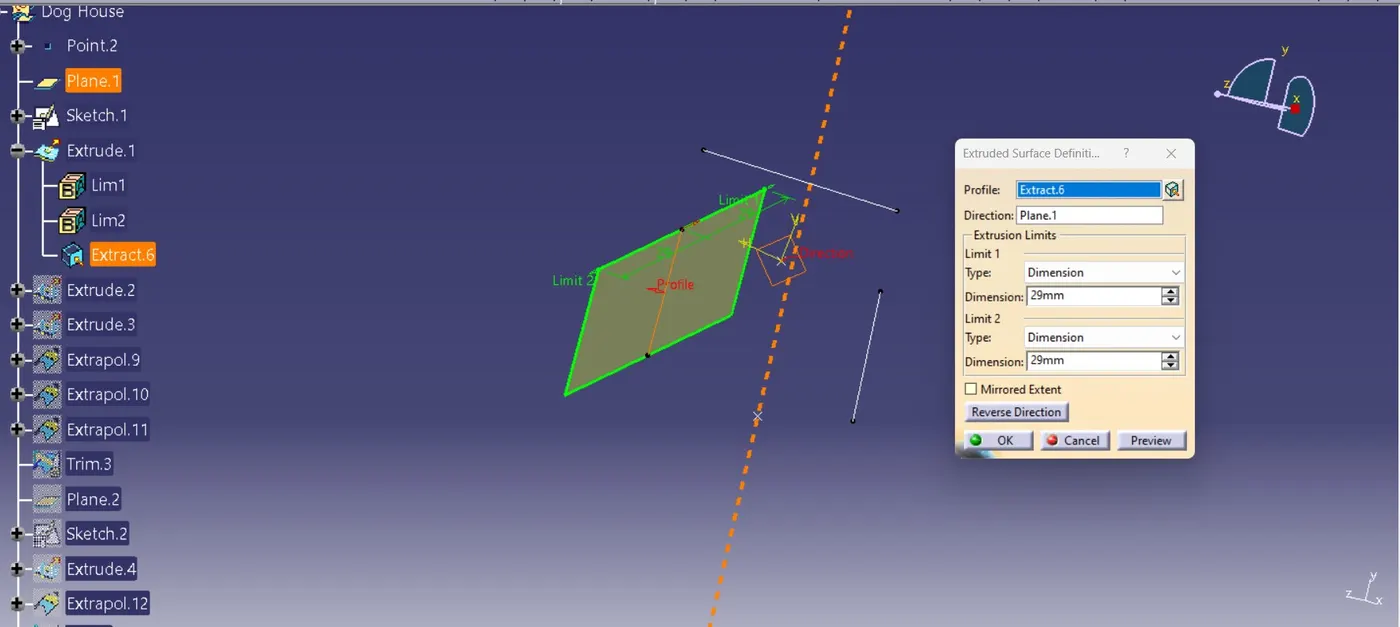
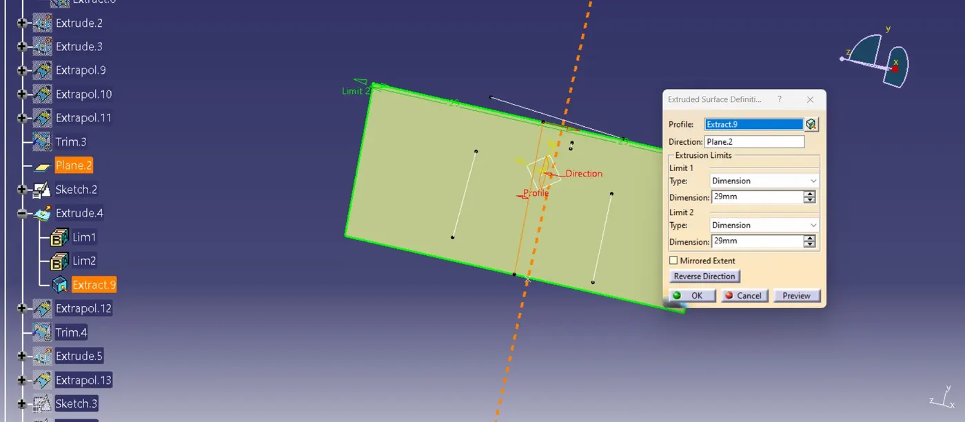
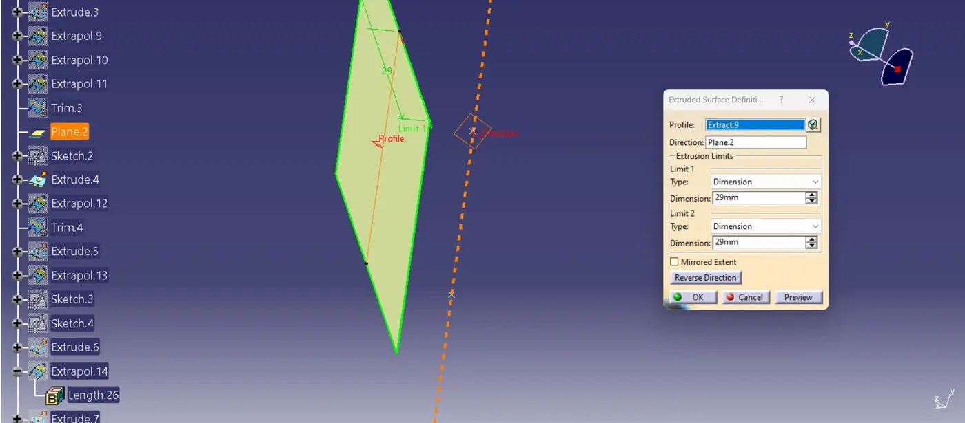
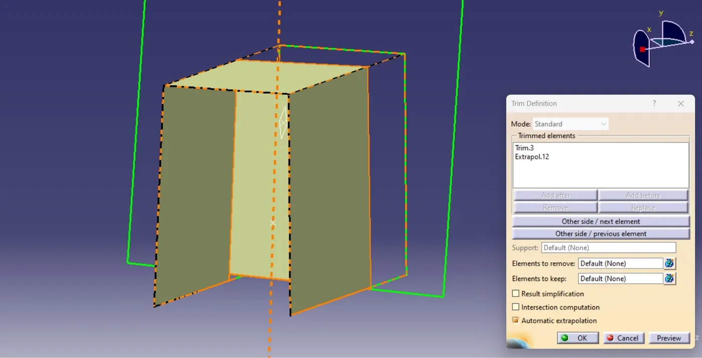
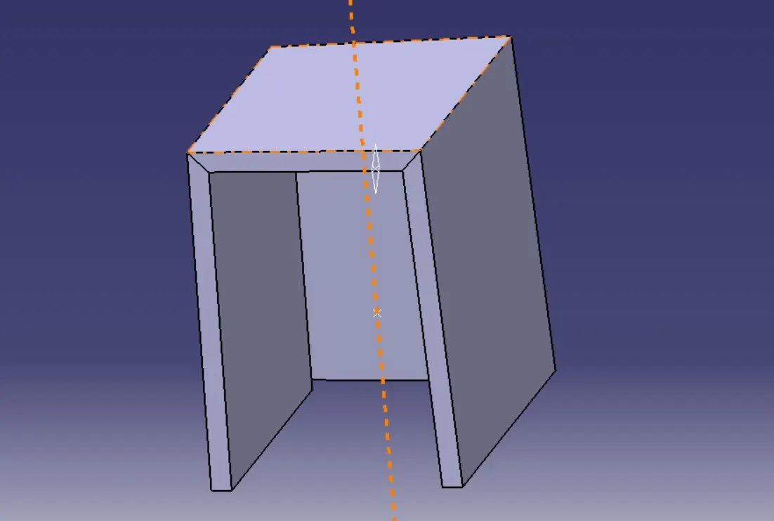
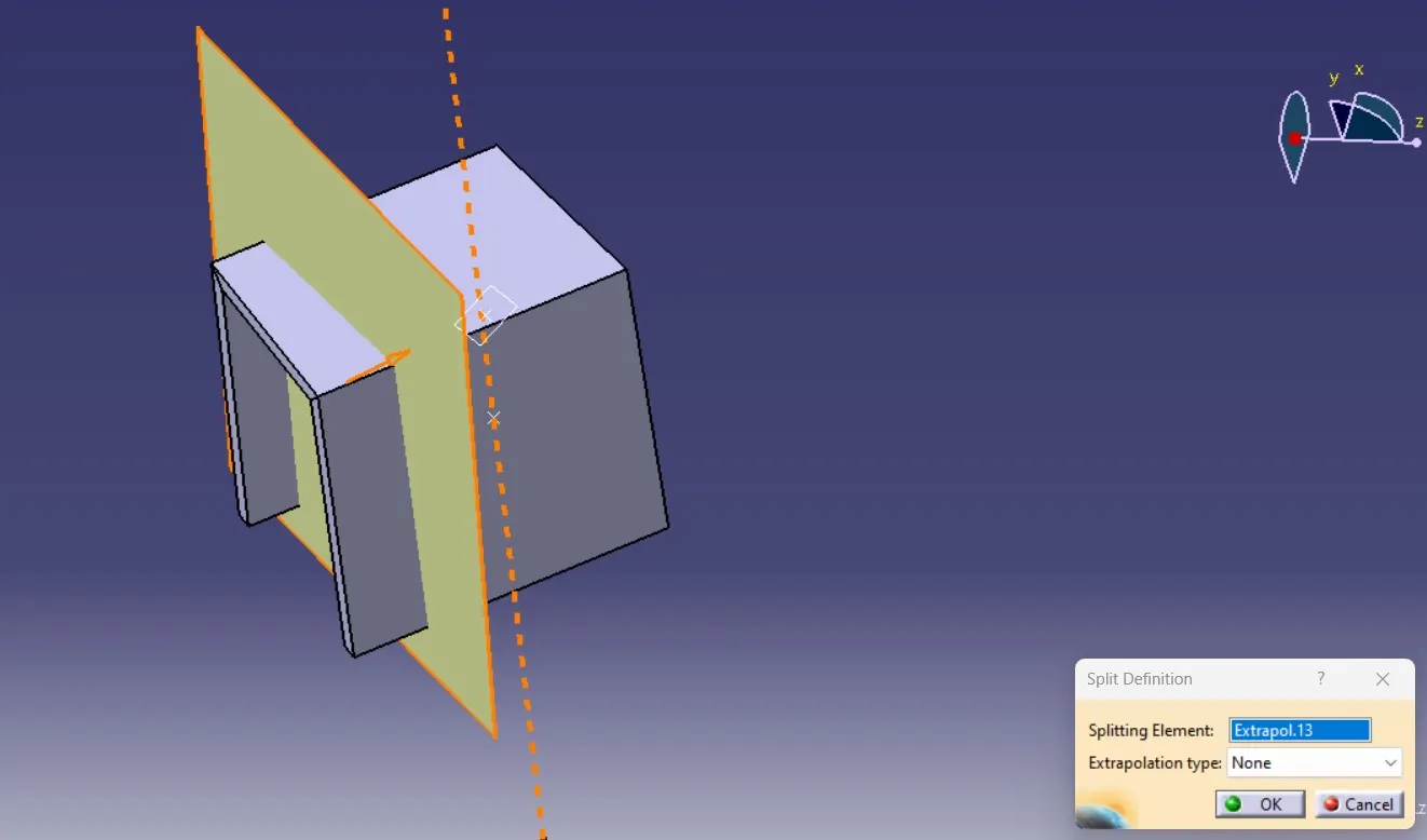
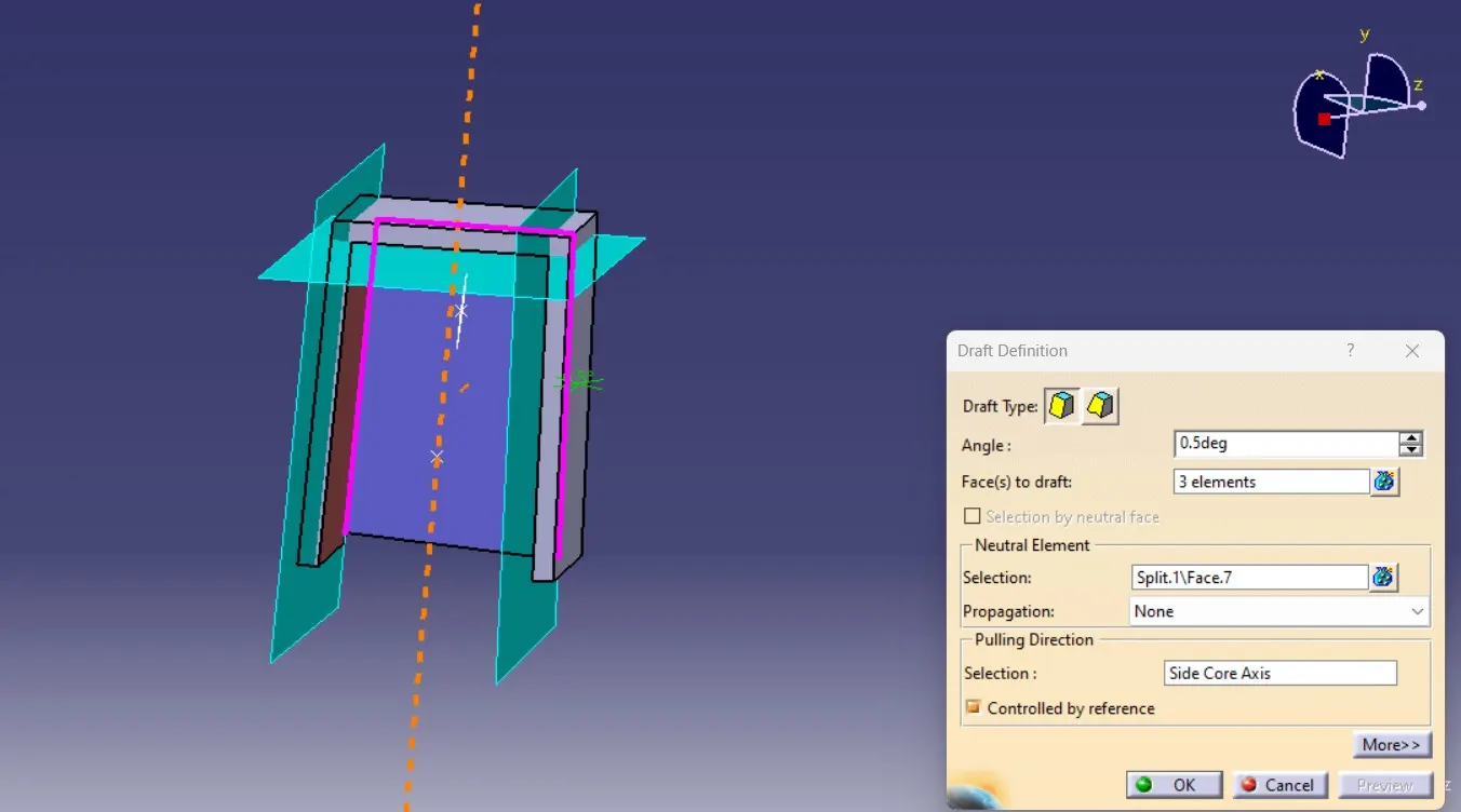
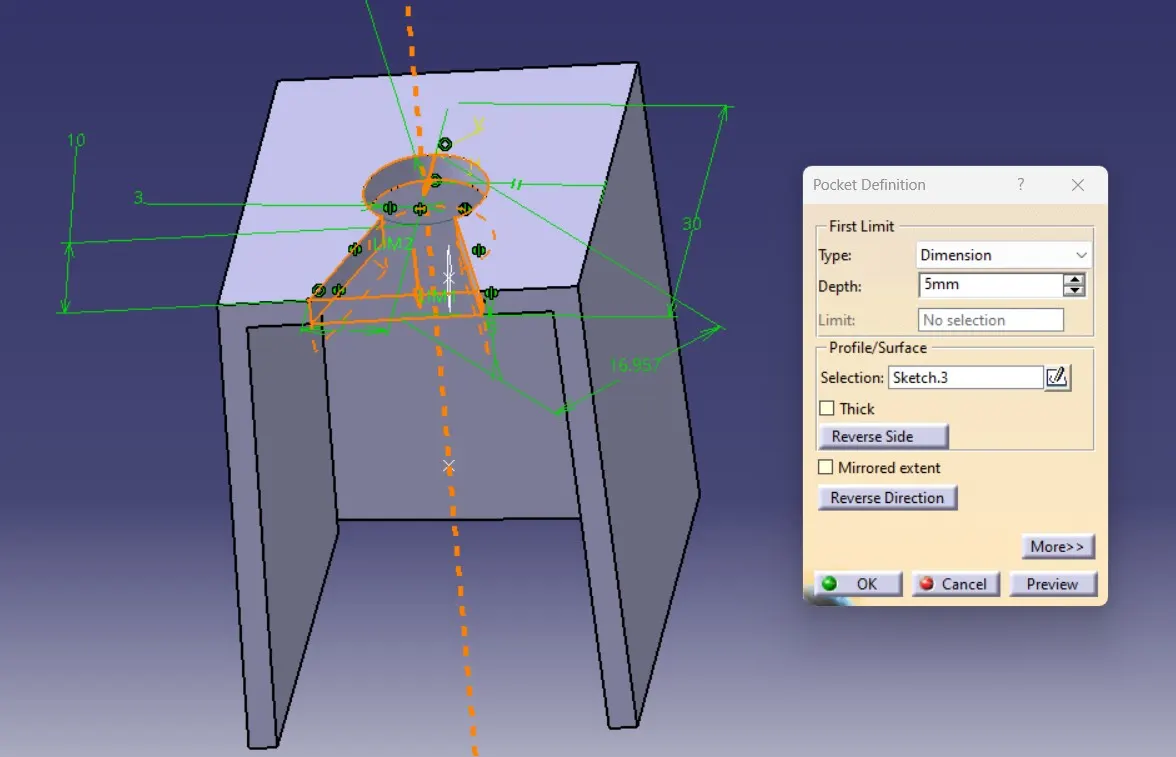
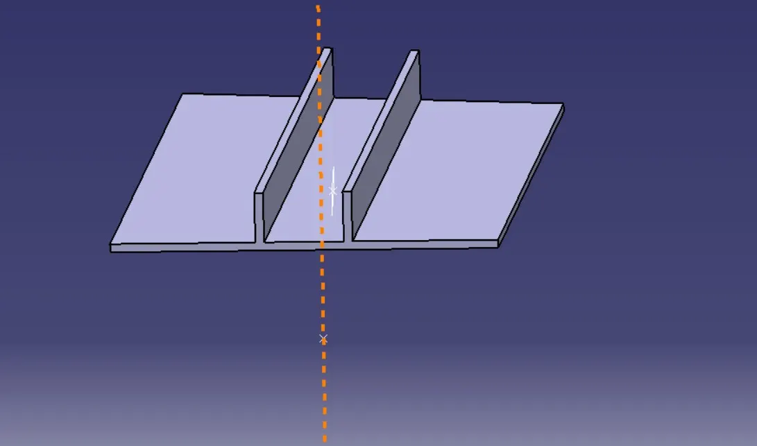
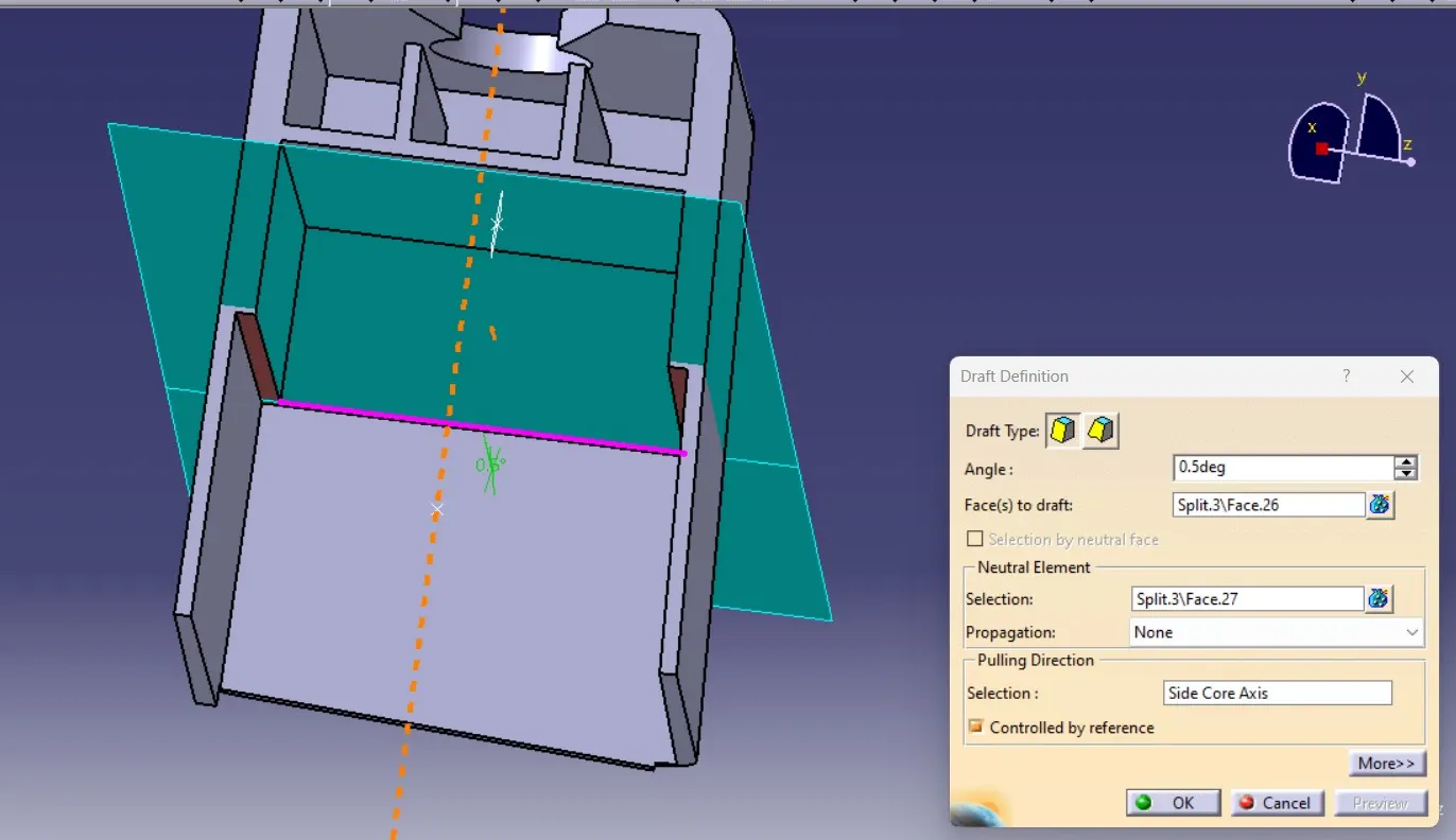
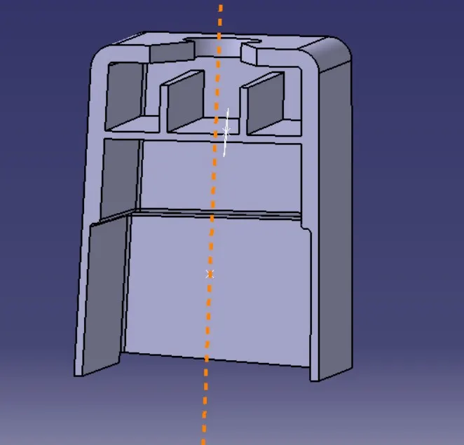
Final dog house created:
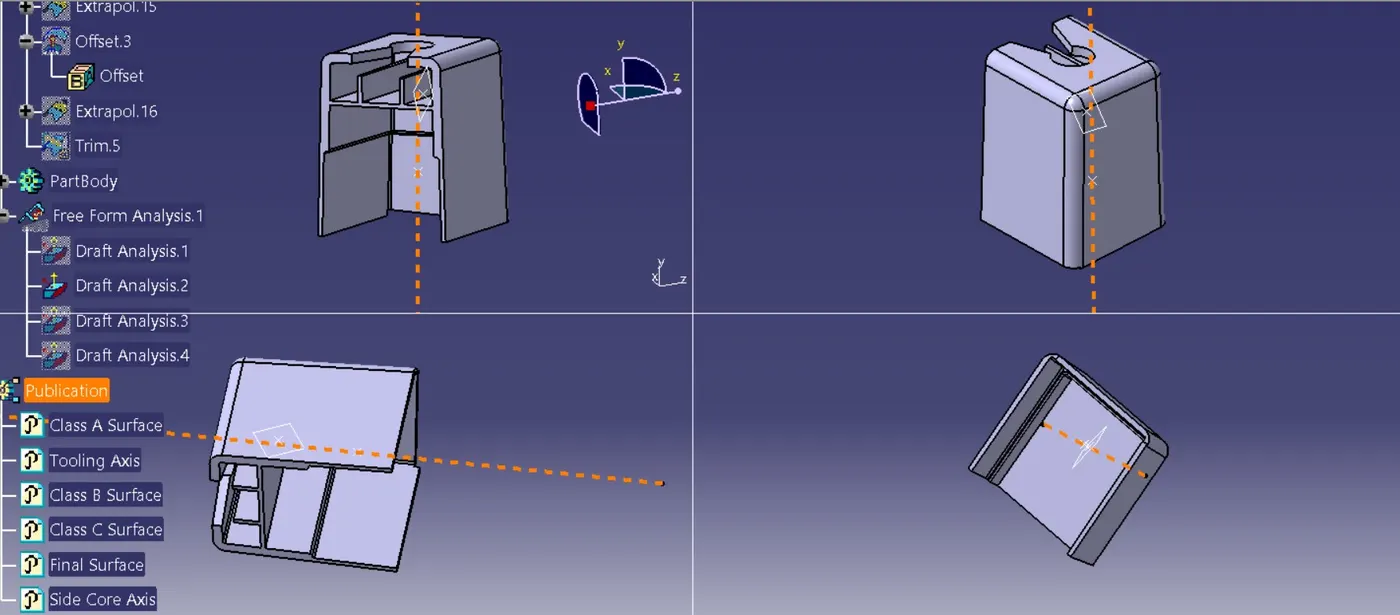
A Pillar with dog house attachment feature:
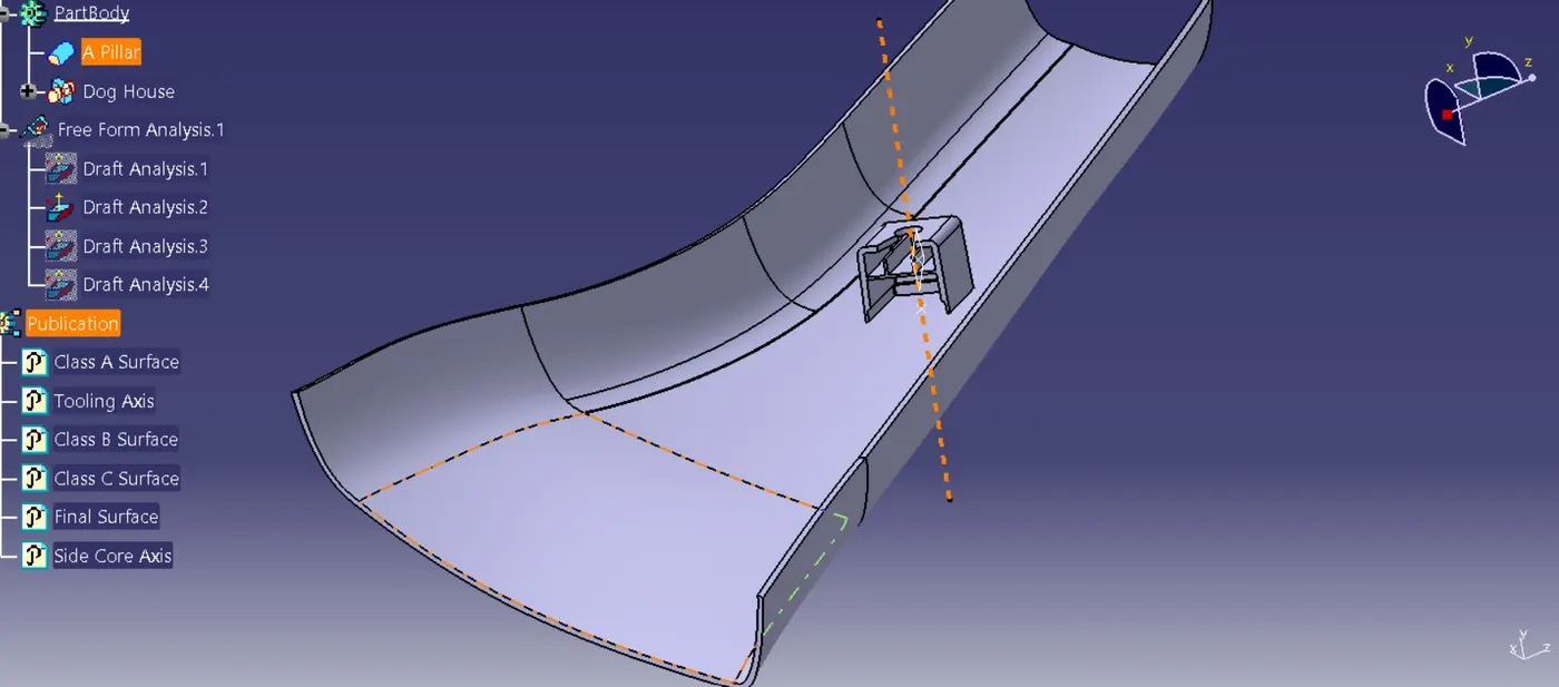
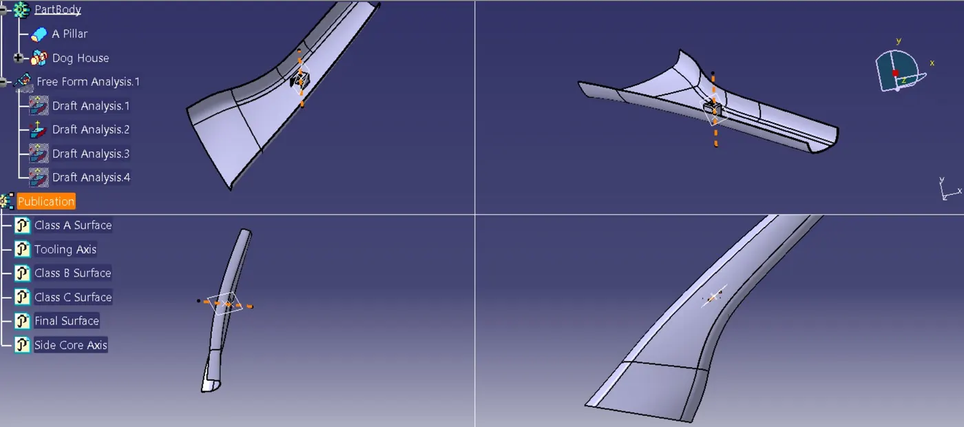
Final Draft Analysis
Draft analysis along the Tooling Axis:
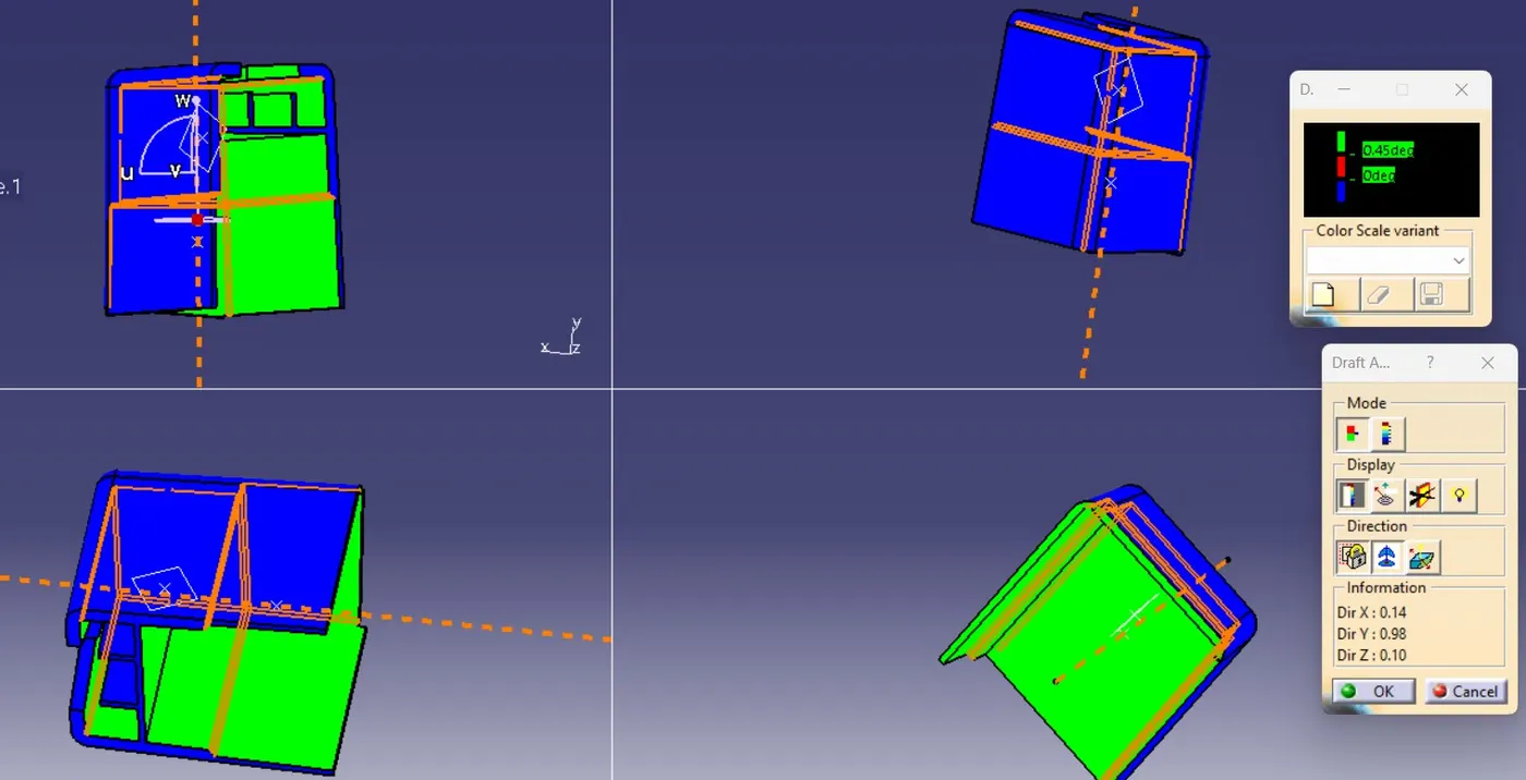
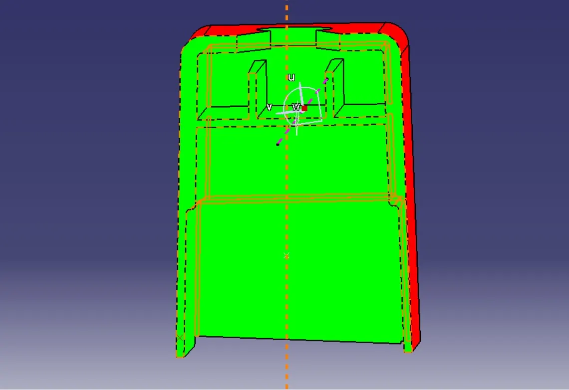
Draft analysis along side core axis:
CONCLUSION
From the given A Pillar master section created solid part model of A pillar with dog house using CATIA. Successfully cleared End draft analysis, conducted along with tooling axis and side core axis to check manufacturability of the A pillar with dog house.