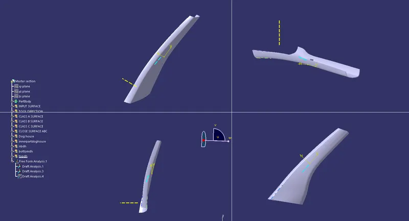
Week 11 - Project - A pillar Design with Master Section
AIM:TO DESIGN A PILLAR WITH GIVEN MASTER SECTION AND ATTACH B SIDE FEATURE (DOG HOUSE)
STEP 1:TO CHECK THE CONNECTIVITY OF GIVEN CLASS A SURFACE
The given CLASS A surface is checked for connectivity using join tool and after joining repair is carried out on the sharp edges that are present in the CLASS A surface and an output wihtout sharp edges is got for the CLASS A sur̥face
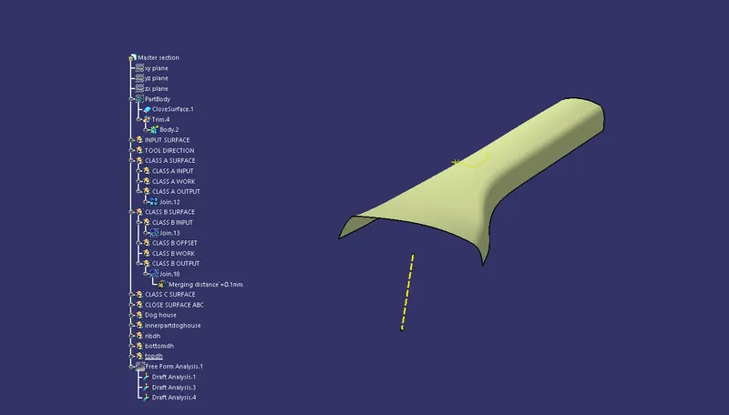
A surface repair is carried out using multi section tool,blend,boundary etc. on every portion with sharp edges .part by part repair is carried out on CLASS A surface
STEP 2:TOOLING DIRECTION CREATION
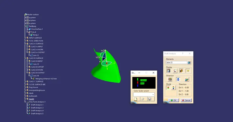
Tooling direction is created on an extracted part of class A surface and method followed is normal to surface method.A point is created on the surface and a line created in point direction in an appropriate direction.Uisng the line a draft analysis is carried out opn the class A surface and line direction is adjusted to compass direction after finding out the best draft direction for the CLASS A surface.
STEP 3:CLASS B SURFACE CREATION
For CLASS B surface creation the input is the output of the CLASS A Surface.The surface is offseted to a desired distance of 2.5mm and the sub elements that can't be offseted is avoided and then proceeded with the offset.Then the side part that went completely missing while offseting had no refrences to create from,so created another offset with automoatic smoothing and global option instead of local and the boundary is extracted from that to create the complete B surface.Tools like multi-section,blend,split and other boundary creating tools.
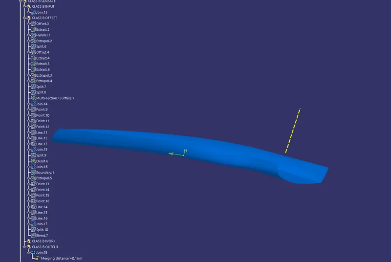
And the whole surface is extrapolated a little bit to ensure proper trimming with CLASS C surface later>
STEP 4:CLASS C SURFACE CREATION
For CLASS C surface creation also the input is CLASS A surface output.CLASS C surface is created part by part using sweep tool by creating boundaries accordingly and in different part different sweep options like with draft direction and with reference surface is used.For C surfacae a sweep angle of 3 is preferably given.
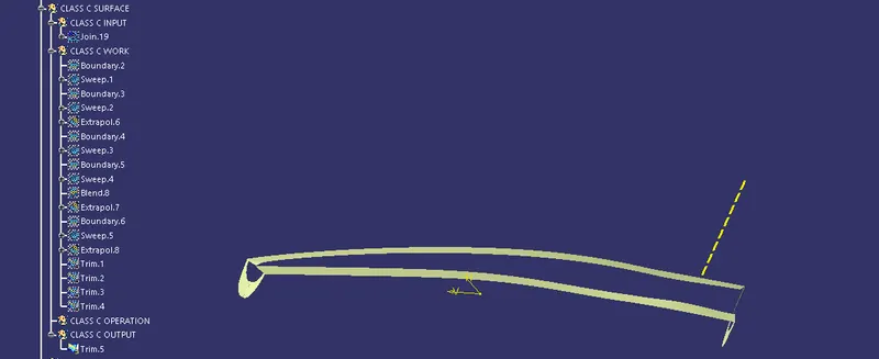
Different parts of C surface is trimmed together to create a single C surface and a small gap that was created between a C surface part is filled using blend tool.After the final trim the final C surface output is obtained.
STEP 5:CLOSURE SURFACE AND SOLID PART CREATION
For closure surface creation CLASS C surface is trimmed with the CLASS B surface and then it is trimmed or joined with CLASS A surface and then we will get the closure surface for the particular part.
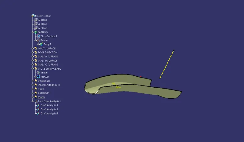
And then using the close surface tool in part design make it into a solid body.
STEP 6:DOG HOUSE CREATION
Dog house is created using the reference of master section and dog house dimesions given.By following just master section the dimensions of the dog house is not proper so we create a plane parallel to a line in the master section and use that plane to create sketches for the parts of dog house.Dog house is created part by part,at first we create the outer part of the Dog house.Then inner smaller cut and then we create the rib in middle portion all created seperately.
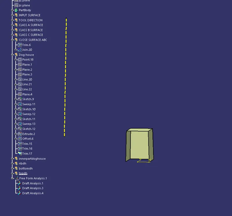
apply thickness of 2.5mm to inside using thick surface tool
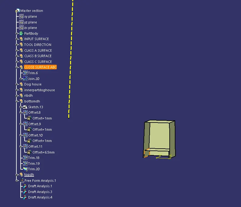
then create the bottom part and apply some thickness and remove it from the top part of the dog house.then create the niddle rib part,
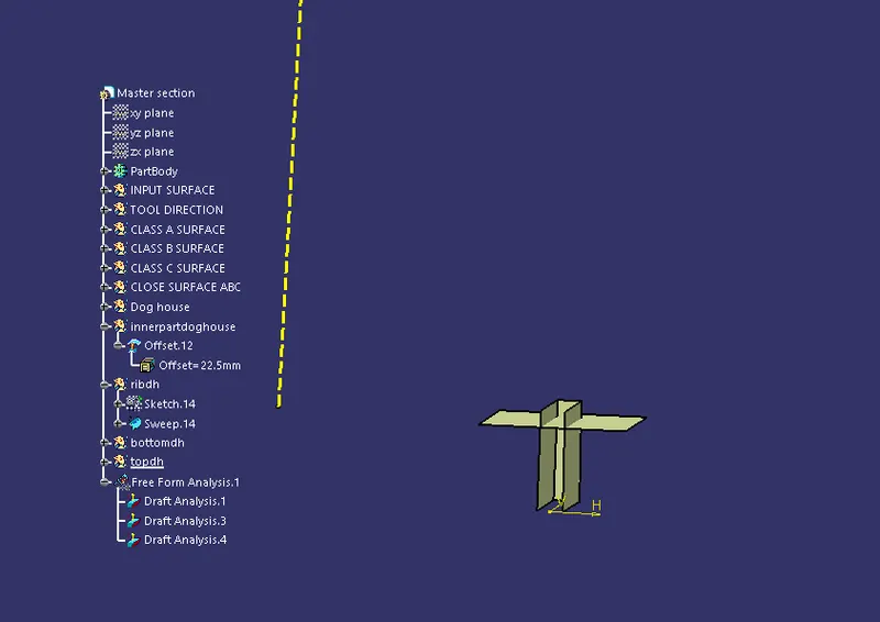
apply thickness for this also and then using union trim remove the unwanted part and obtain the final part of dog house and then union trim it with the partbody.
Before applying union trim eith the partbody carry out draft analysis for the dog house alone.
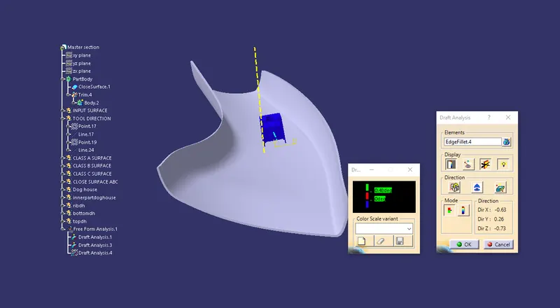
DIFFERENT VIEWS OF THE COMPONENT: