Week 11 - Project - A pillar Design with Master Section
--------------------------------------------- A PILLAR DESIGN WITH MASTER SECTION -------------------------------------------
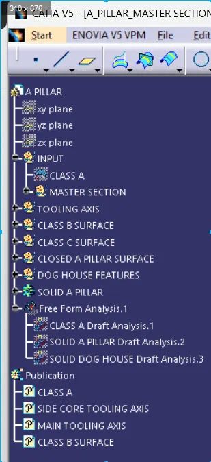
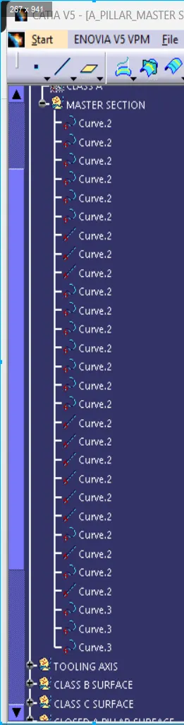
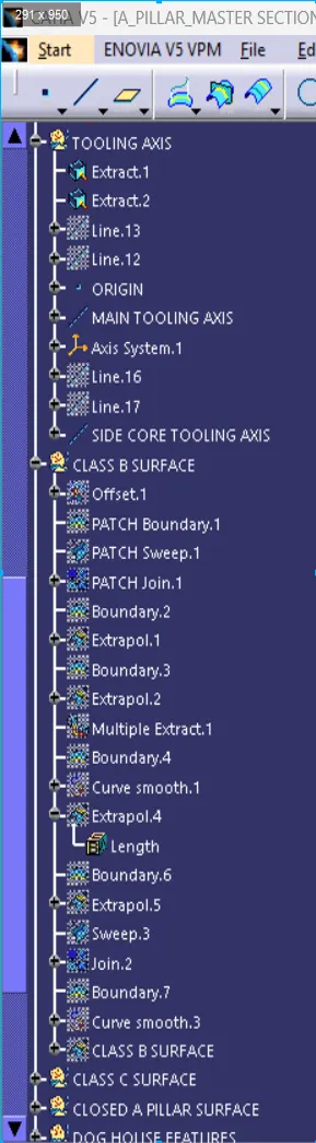
- TREE STRUCTURE
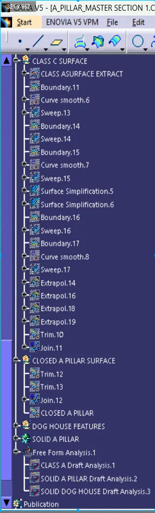
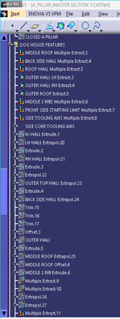
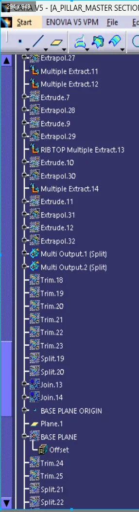
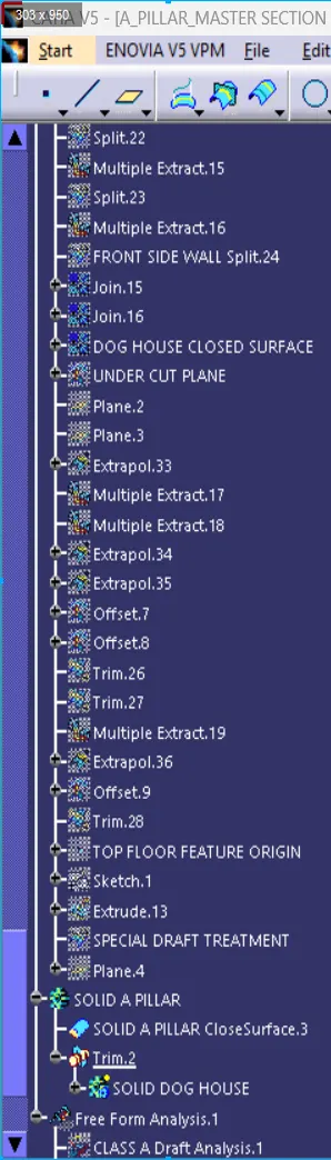
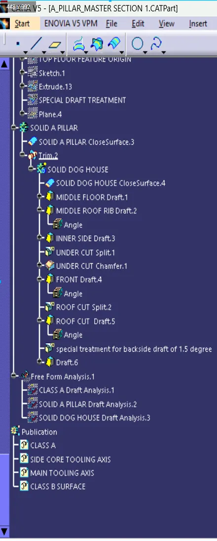
- SCREENSHOT OF SOLID DOOR TRIM IN VARIOUS ORIENTATIONS
FRONT VIEW
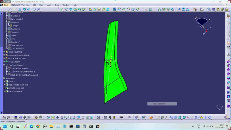
SIDE VIEW
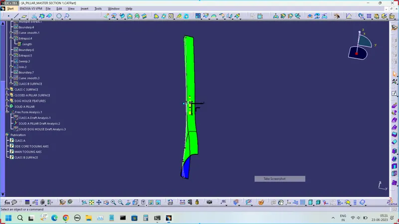
TOP VIEW
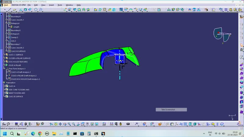
ISOMETRIC VIEW
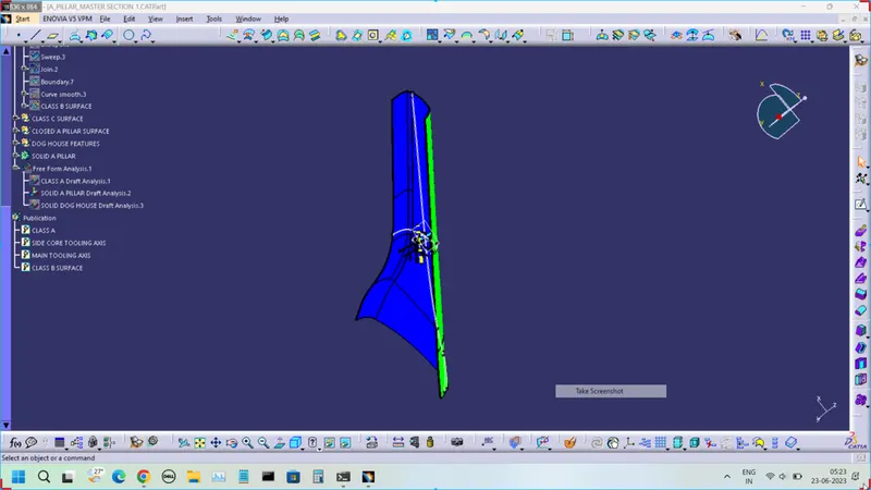
1. CREATION OF TOOLING AXIS
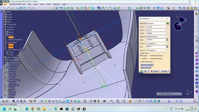
MAIN TOOLING AXIS
- Use the Master section of the A-pillar and especially the section of the dog house which is shown in the below image.
- Insert axis-system at the origin point and the origin point will be the intersection of the back wall and side wall section which will locate on the midpoint.
- Create a line with the bisecting method in which the point will originate and the side wall section of the dog house will bisect the line
- Now this line will be the Main tooling axis, So for proving this line we will test draft analysis on CLASS A surface.
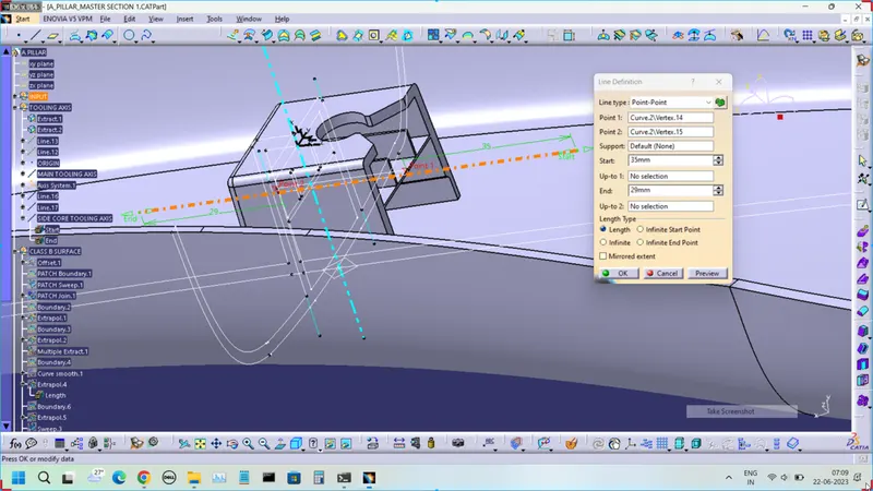
SIDE CORE TOOLING AXIS
- select the point-to-point method in which choose 2 points of the master section (dog house) which will divide the doge house longitudinally.
- This line will be perpendicular to the main tooling axis.
- which will act as the side core tooling direction for Dog House.
2. PERFORMING DRAFT ANALYSIS ON CLASS A SURFACE AND FINAL COMPONENT
- Select the Feature Draft Analysis
- Click the part and define the tooling Direction which is the main core and side core tooling axis one by one.
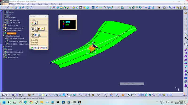
- From the main core tooling axis, Green Side is showing that the part will be made according to the Draft Angle which is 2.9 degrees and there will be no erosion between the Tool and Plastic parts but due to class A surface defect some errors will appear.
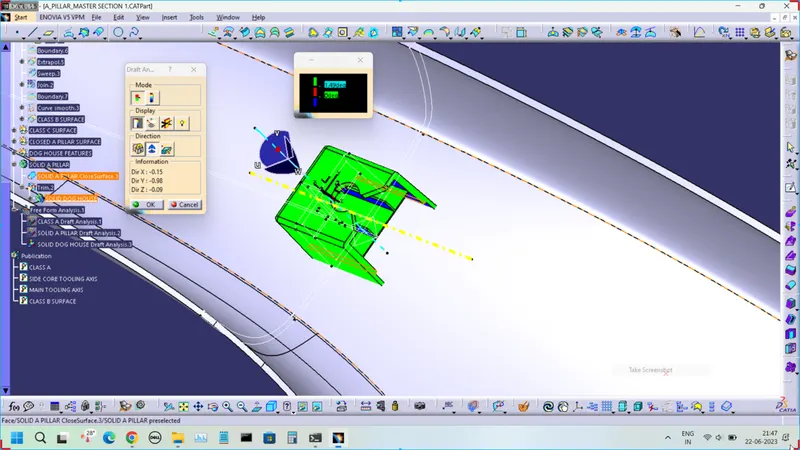
- from the above main tooling axis, we can perform draft analysis by 1.49 degrees because the outer surface of the dog house is drafted by 1.5 degrees per side of the wall.
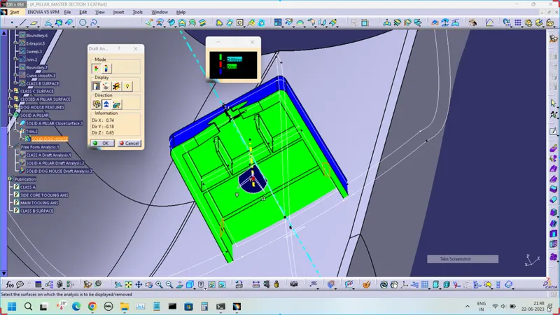
- From the side core tooling axis, Green Side is showing that the part will be made according to the Draft Angle which is 0.49 degrees and there will be no erosion between the Tool and Plastic parts.
- The blue side is showing a negative Draft angle (interference) or it is impossible to draw the part according to the draft angle.
DRAFT ANALYSIS ON CLASS A SURFACE A PILLAR DESIGN WITH RESPECT TO THE MAIN CORE TOOLING AXIS OF 3 DEGREE DRAFT
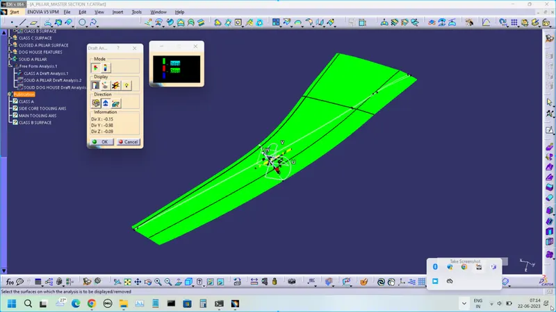
DRAFT ANALYSIS ON SOLID A PILLAR DESIGN WITH RESPECT TO THE MAIN CORE TOOLING AXIS OF 2.9 DEGREE DRAFT
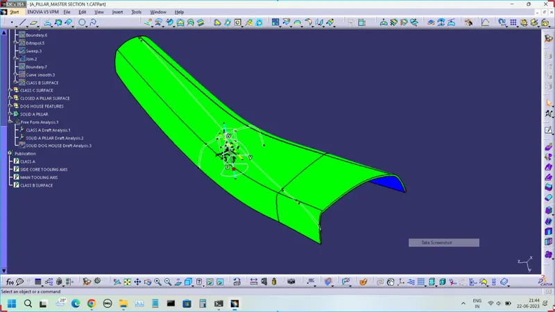
DRAFT ANALYSIS ON SOLID DOG HOUSE DESIGN WITH RESPECT TO THE MAIN CORE TOOLING AXIS OF 1.49 DEGREE DRAFT ON OUTR WALL
DRAFT ANALYSIS ON SOLID DOG HOUSE DESIGN WITH RESPECT TO THE SIDE CORE TOOLING AXIS OF 0.49 DEGREE DRAFT INSIDE
3. CREATION OF CLASS B AND CLASS C SURFACE
Class B surface is taken offset of 2.5mm from class A surface to inside. Then some patches were repaired by fill or multi-section command.
Class C surface is taken at a 3-degree draft angle with a reference surface and from the tooling axis.
CLASS B SURFACE
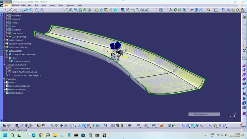
CLASS C SURFACE
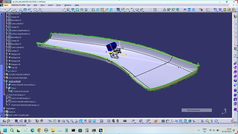
- Create closed body
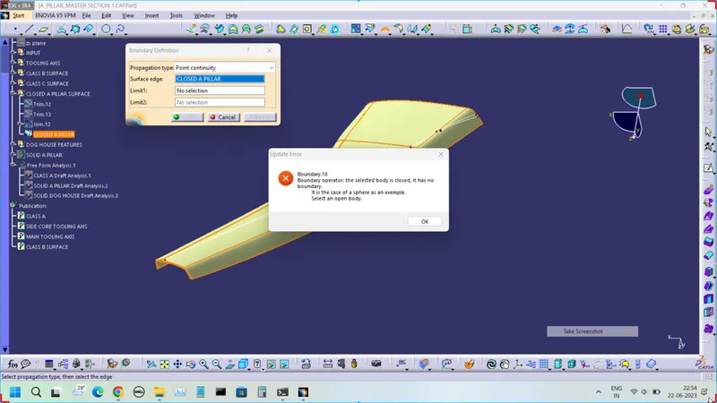
4. CREATION OF ENGINEERING FEATURES (DOG HOUSE)
- Use the dog house master section with a side core axis.
- Extract and extrapolate the side wall surface with the help of extracted all lines of the doghouse master section.
- trim all side surfaces of the dog house and make them closed surfaces and the thickness of the dog house will be according to the master section.
- Use the closed surface command to make a solid dog house.