Week 11: Project 2 - Emission characterization on a CAT3410 engine
AIM: Emission characterization on a CAT3410 engine.
OBJECTIVE:
- To create cut-plan animations showing Soot, Nox and UHC and compare them between the omega and the open-w pistons.
- To compare the imep and power values graphically.
INTRODUCTION
- With respect to the mathematical modelling of pollutant formation in engine simulations ,nitrogen oxides and soot are basically the solitary points of focus.
- The soot formation is being before the presence of polycyclic aromatic hydrocarbons(PAH).
- The first step is the growth of the PAH by conglomeration of molecules.
- When these are arranged in 3-D, referred to as particles.(particle inception or nucleation)
- The particles are subjected to surface growth by addition of mainly acetylene (`C_2H_2`),and they further increase size by coagulation.
- During this process , `H_2`, is continously abstacted such that the resulting soot particles are finally characterized by high carbon fraction.
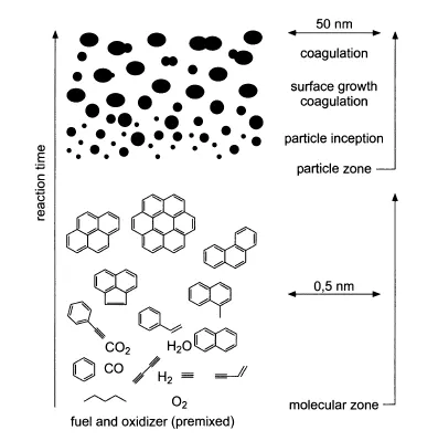
Fig. Schematic reaction path leading soot formation in premixed flames.
Semi-global Soot Models :
- It describes the formation and oxidation of soot particles by two or several global reaction steps.
- Two step model is proposed by Hiroyasu et al. and it describes the change in the soot mass by the equation :
`del/(delt)(m_s)=del/(delt)(m_s,f)-del/(delt)(m_s,o)`
`del/(delt)(m_s,f)=A_f*(m)_(f,v)*P^(0.5)*exp[-E_(s,f)/(barR*T)]` ............soot formation
where `m_(f,v)`= mass of fuel vapourized
`A_f`=pre-exponential constant.
`del/(delt)(m_(s,o))= A_o*m_s*(P_(0_2))/P*P^(1.8)*exp[-E_(o,x)/(barR*T)]`............soot oxidation
where `m_s`= mass of soot
- Soot formation is limited to a temp. range between about 1200 and 2000k .
- It can be explained by the fact, that soot formation is nrrding radical precursors such as `C_3H_3`,that are not present in lower temperature.
- During the expansion stroke ,the oxidation of previously formed soot comes to a stop brcause the concentration of `O`atoms and `OH`radicals that are important in the oxidation process becomes too small to attack the soot particle.
NOx
- The thermal formation of nitric oxide is described by the so called Zeldovich mechanism.
- It describes the breakup of Nitrogen molecule by oxygen atom and the subsequent oxidation of 'N' atoms.
`N_2+O=NO+N` k1= `7.6*10^(3)*exp(-38000/T)`
`N+O_2=NO+O` k2= `6.4*10^9*exp(-3150/T)`
N+OH=NO+H k3=`4.1*10^3`
- The production of N atoms proceeds only at high temperature.This is obvious from high activation energy(38000k).
- As the power stroke initiate ,considerable amount of NO is formed in the hot product region.
CASE SET UP
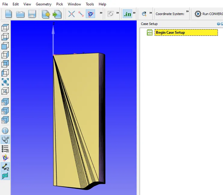
Fig.1 Open-W piston
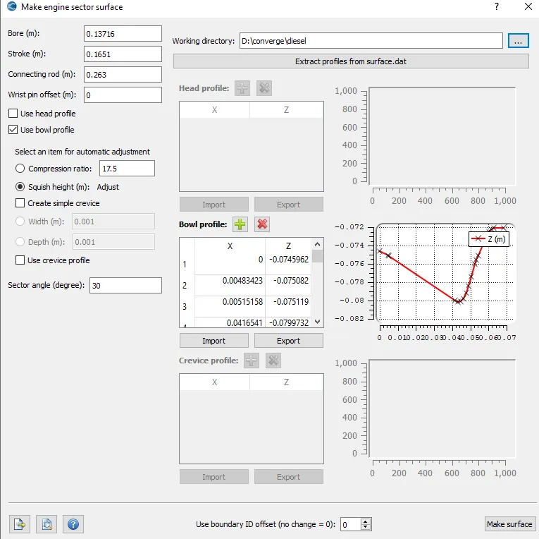
Fig.2 Engine sector surface
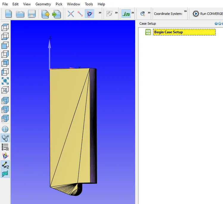
Fig.3 Omega piston
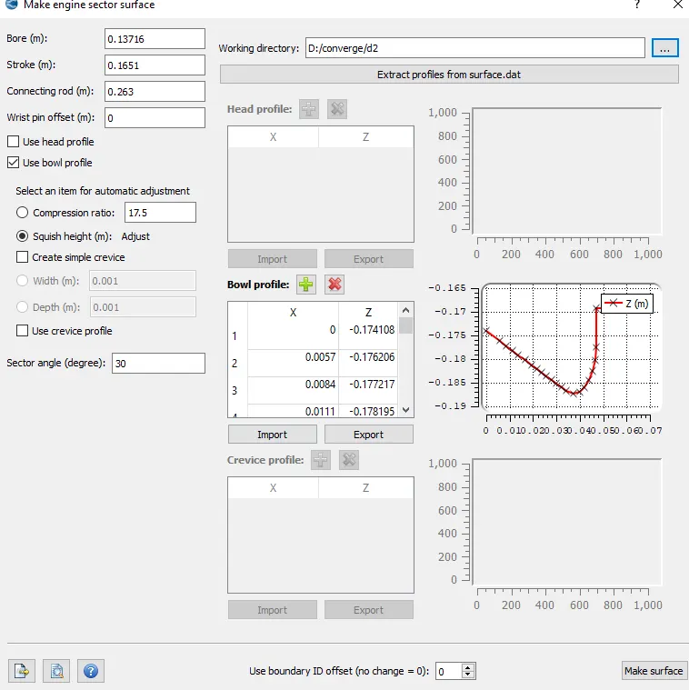
Fig.4
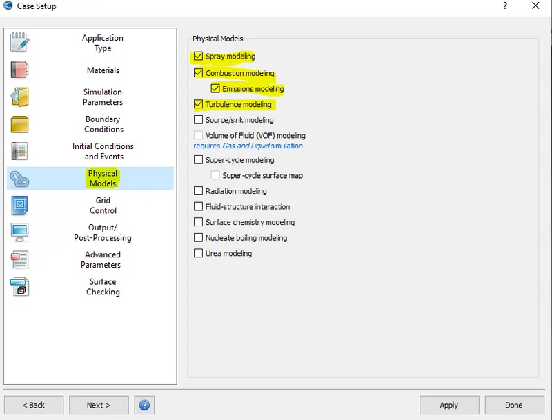
Fig.5 Physical models used in the set up
Fig.6
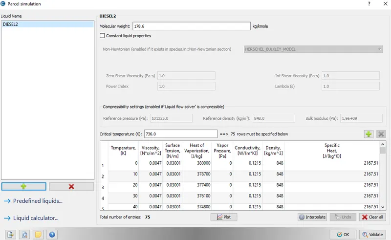
Fig.7 Properties of fuel Diesel2
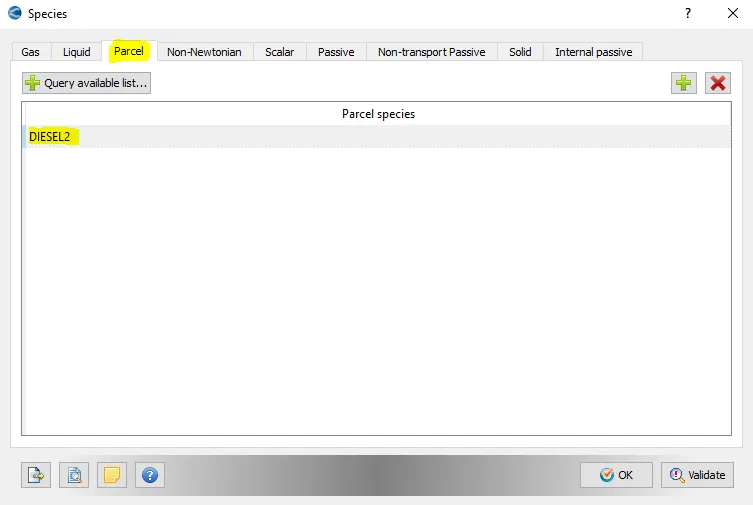
Fig.8
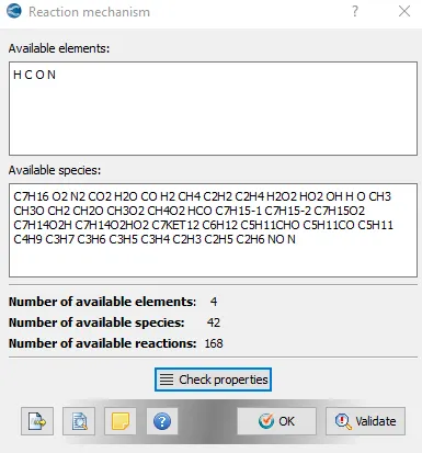
Fig.9 Available elements and species
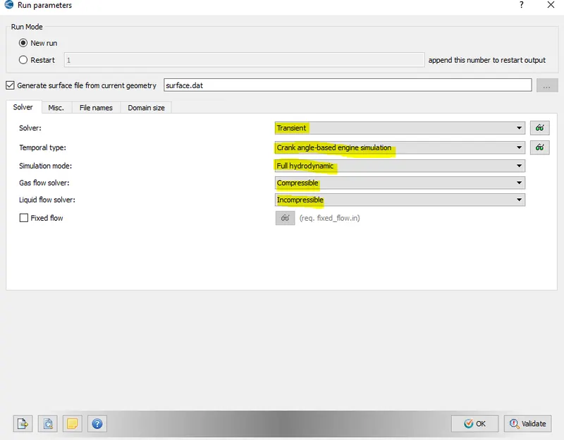
Fig.10
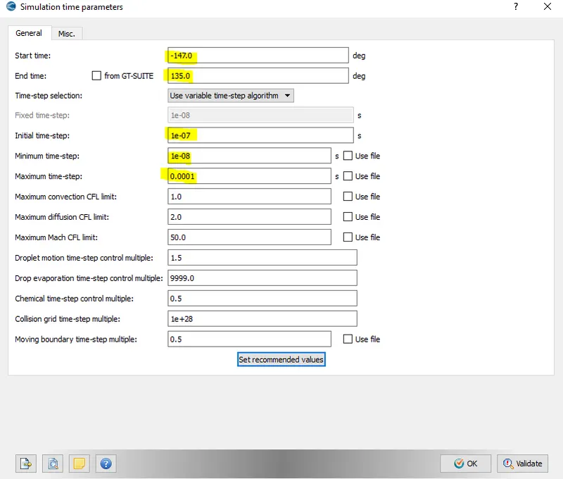
Fig.11 Simulation time parameter
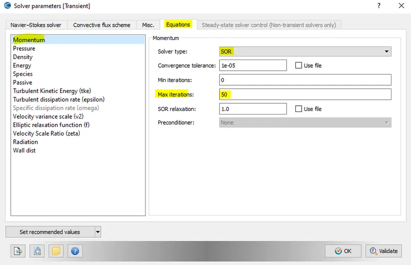
Fig.12 Solver parameter
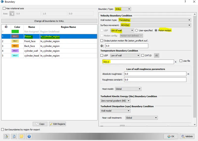
Fig.13 Boundary case set up for piston
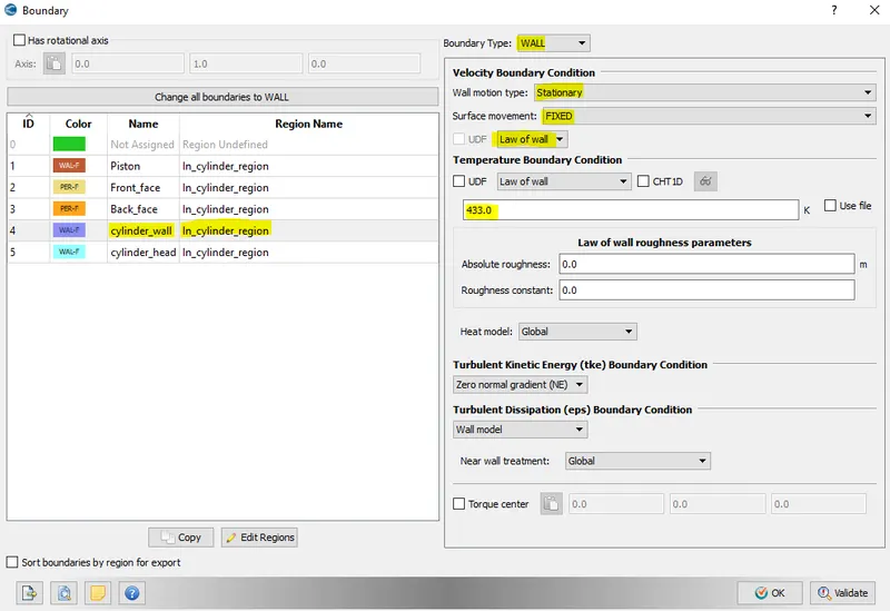
Fig.14 Boundary case set up for cylinder wall
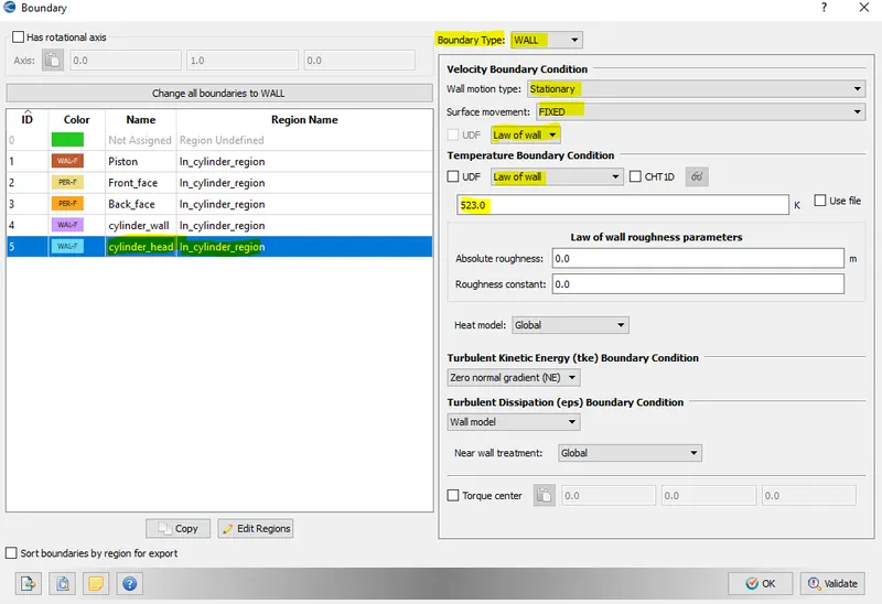
Fig.15 Boundary case set up for cylinder head
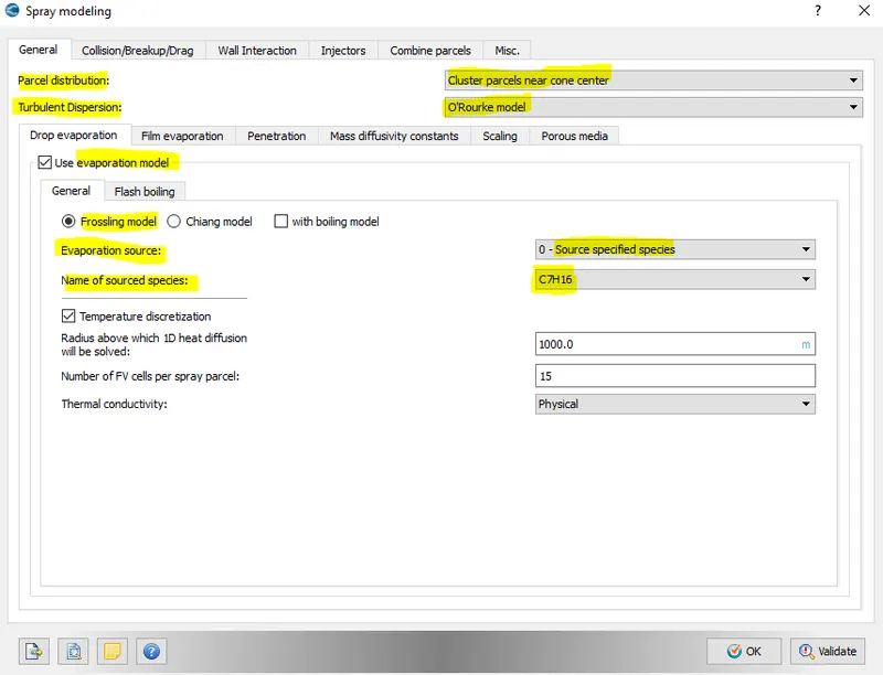
Fig.16 Spray Modelling case set up
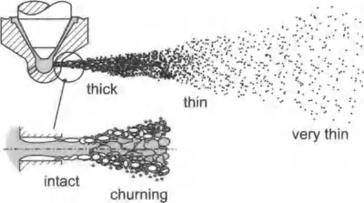
Fig. Schematic illustration of different flow regime
- When the droplet spacing is small the boundary layer around a droplet may be affected by an adjacent droplet.
- In the intermediate thin spray regime, the liquid phase still accounts for a noticeable mass fraction and there is considerable momentum transfer from the droplets to the gas phase , which in turn affects other droplets again.
- This regime is characterized by both volume and mass fractions of the liquid phase that are negligibe compared to ones of the gas phase.
- Generally there are two possible ways of solving the spray equation in addition to gas phase conservation equation :
- CDM ( Continuum droplet model): Imposes high demand on computer memory and power.
- DDM ( Discrete droplet model) : It describes the spray droplets by stocastic particle( predicted by statistics) which are ususlly refered to as parcels.
- These parcels are viewed as identical,non-interacting droplets and they are tracked through physical space in a lagrangian manner.
Spray atomization :
CONVERGE uses sub-grid models for the spray processes that occur on the length scales that are too small to be resolved.
Parcels undergo several physical processes:
- Primary breakup
- Secondary breakup
- Drop drag
- Collision and coalescence
- Turbulent dispersion
- Evaporation
- The primary breakup describes the breakup of the intact liquid phase into first ligaments and droplets.
- Later on,large initial droplets further distorted and sbsequently broken up into smaller secondary droplets.
- The secondary breakup takes place downstream of nozzle i.e, within thick ,thin and very thin spray regimes.
- Primary breakup at nozzle exit caused due to :
(a) Turbulence within iquid phase.
(b) Implosion of cavitation bubbles.
(c) Aerodynamic forces acting on the liquid jet.
- Due to the pressure drop across the injector nozzle the liquid fuel is accelerated within the small nozzle holes.
- High level of turbulence is generated within the liquid phase and has a destabilizing effect on the jet once it exits the nozzle hole.
Droplet collision and coalescence :
- Droplet collision have a strong influence on mean droplet size and spatial distribution and affect further processes such as mass,momentum and energy transfer between gas and droplets.
- The frequency of droplet collision is greatest in the dense spray regions close to the nozzle near spray axis.
Impingement regime
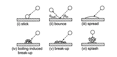
- Depending on the impact condition the outcomes of droplet-wall interaction can be classified as:
- Stick to the wall in nearly spherical form.
- Rebound:Either due to gas trapped between the drop and liquid wall film or due to fuel vappor layer present on wall.
- Spread out to form liquid wall film (or) break up into smaller droplets due to boiling induced or kinetic energy of incoming droplet.
- splash
Evaporation Modelling
- Poor evaporation will typically cause increased soot and unburned hydrocarbon emissions.
- Rapid evaporation,especialy during the ignition delay in CI engine will cause an increase in NOx because of rapid premixed combustion associated with high temperature.
Modelling aspproaches for droplet:
- Infinite diffussion model( assumes a well mixed droplet interior without spatial gradients at any time).
- Diffusion limit model ( assumes one dimensional temp.)
- Vortex model ( It considers an inviscid flow region inside the droplet)
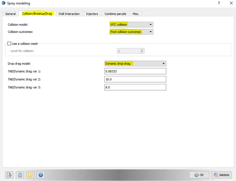
Fig.17 Spray modelling set up
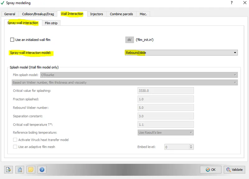
Fig.18 Spray modelling set up
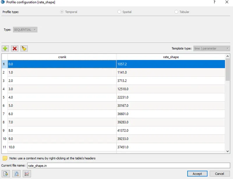
Fig.19
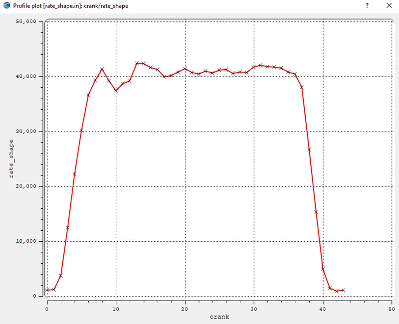
Fig.20 Rate shape
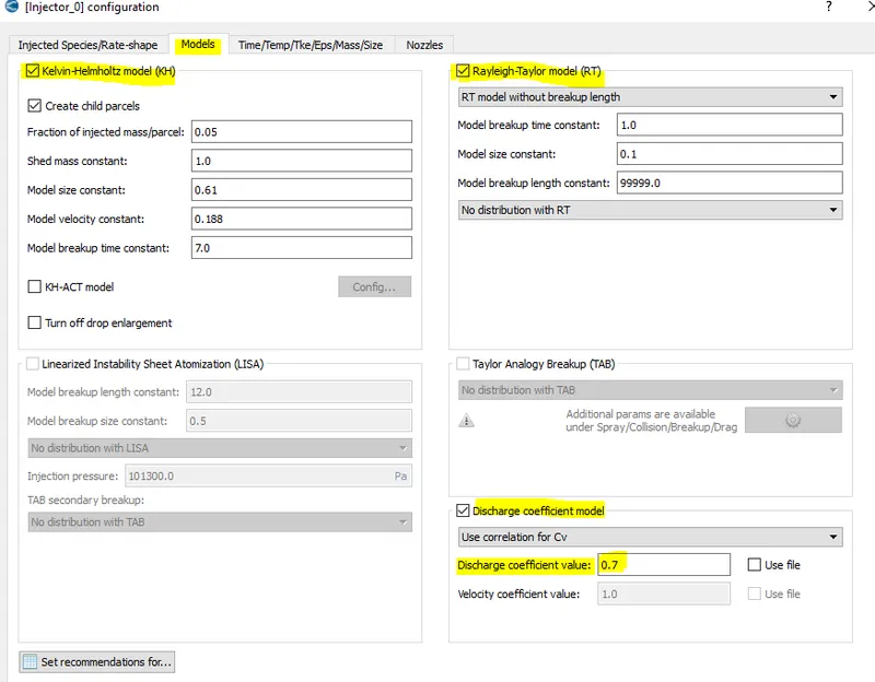
Fig.21 Breakup model set up
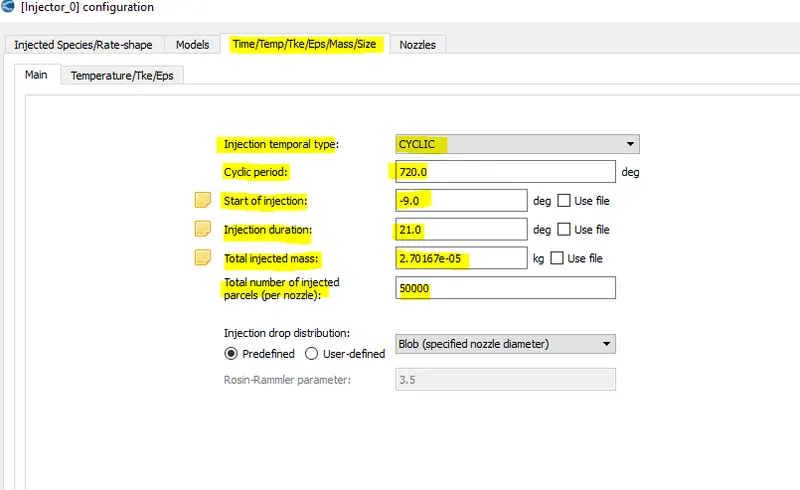
Fig.22 Injection timing set up
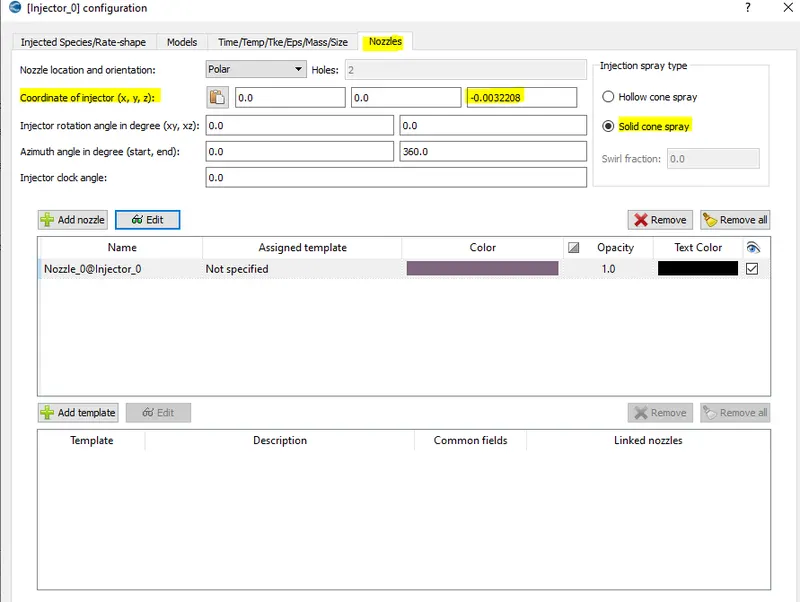
Fig.23 Nozzle configuration set up
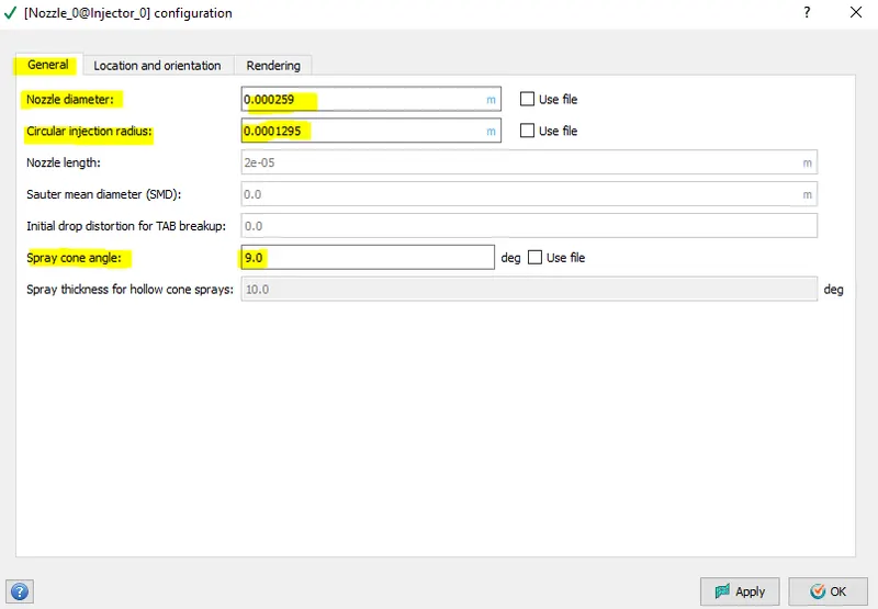
Fig.24
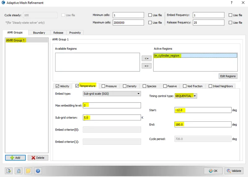
Fig. Temperature AMR
- Adaptive mesh refinement is necessary to capture the temperature variation during the combustion process and to figure out where the max. temperature is occuring so that it is convienient for analysis.
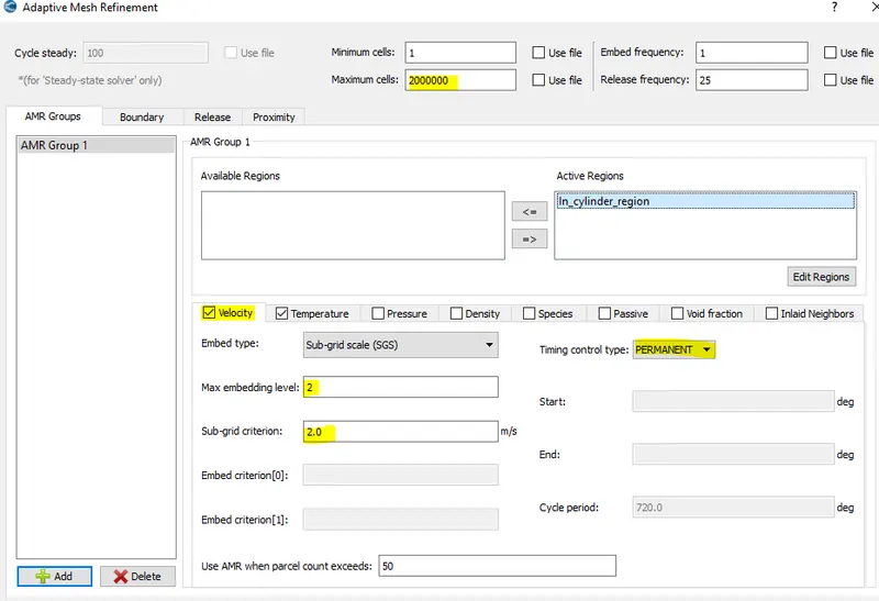
Fig. Velocity AMR
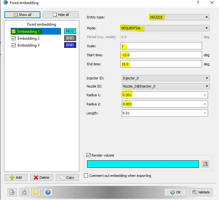
Fig. Fixed embedding
- Here the region near nozzle is refined through embedding to capture the spray behaviour.
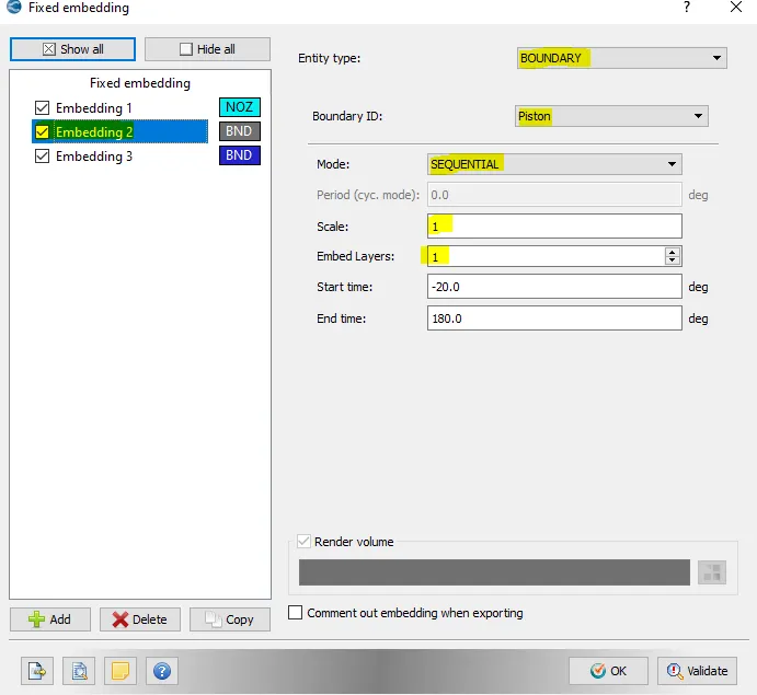
Fig. Fixed embedding
RESULTS
PLOTS
|
|
|
 |
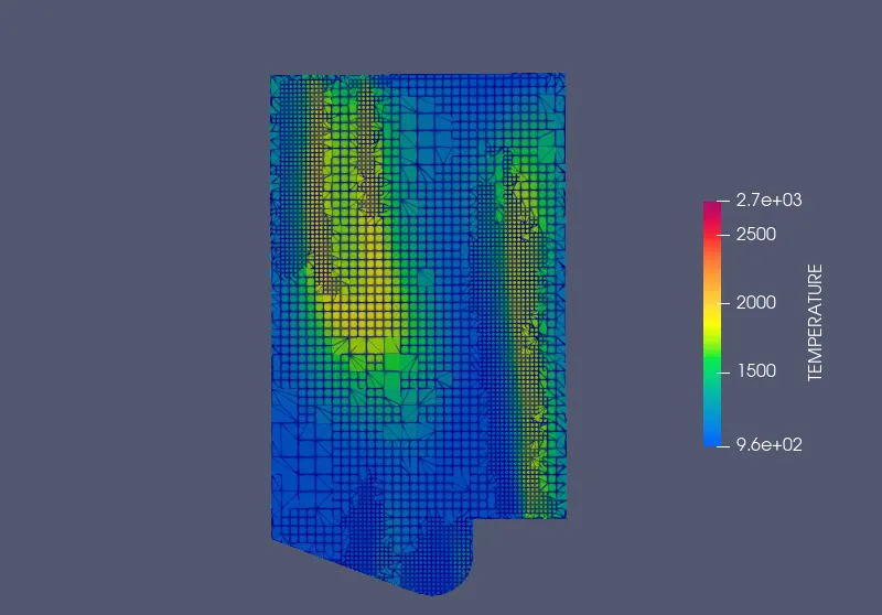 |
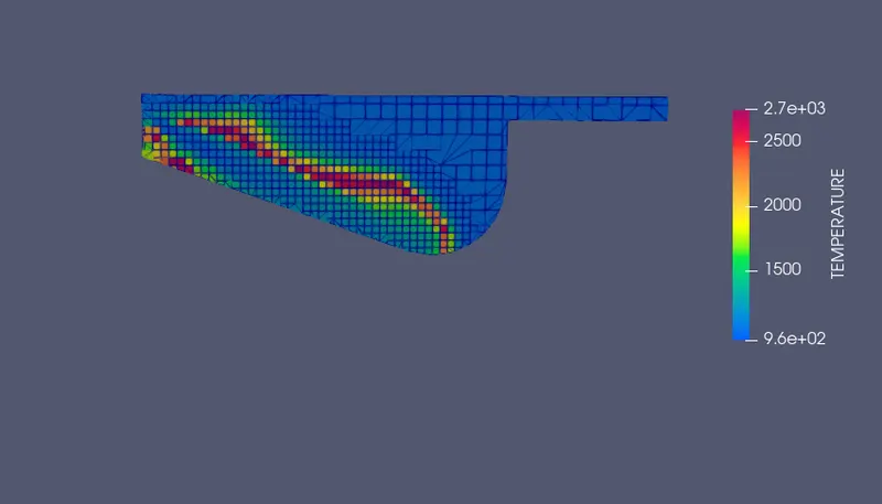
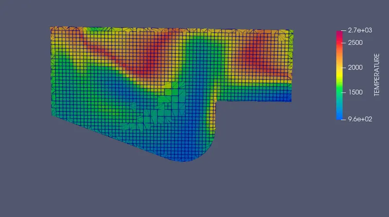
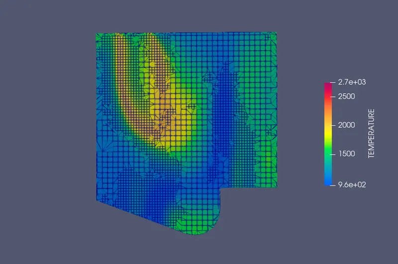
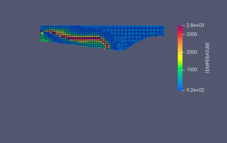
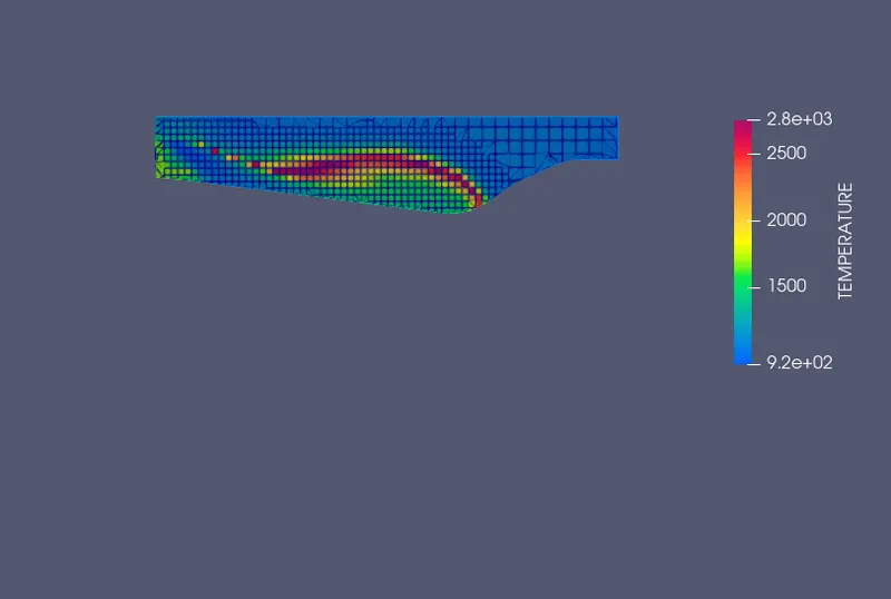
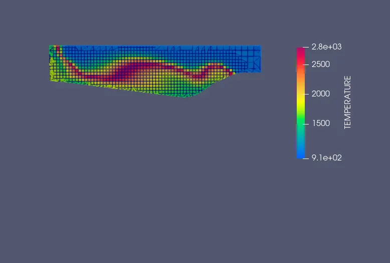
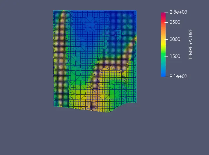
Fig.25 Omega piston Temperature distribution inside the cylinder
- As far as omega piston is concerned the above figure depicts the temperature variation inside the cylinder domain after the ignition has started.
- We figure out that the the spray has greater penetration length as compared to Open-W piston.The most of liquid spray mass gets atomized and more heat is released after the ignition.
- It is expected to have more NOx emissions as compared to Open-W piston.
- At mid of expansion stroke we have sufficient temperature(2000-2500 K) for unburned hydrocarbon to oxidize, therby reducing soot and hydrocarbons.
 |
 |
 |
 |
 |
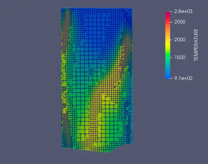 |
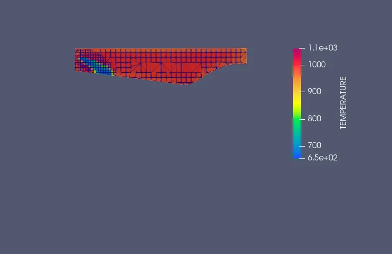
Fig.26 Open W piston Temperature distribution inside the cylinder
- In this piston type we are finding that the fuel spray is directly hitting to the piston surface so that some fuel spray mass is not actively participating in the combustion process,rather after some crank angle.
- For this reason the temperature is lower as compared to omega piston.
- NOx is getting low as compared to omega piston, so it is best choice for emission point of view if the requirement is to reduce the NOx emission.
- As NOx reduces there is significant soot formation as compared to omega piston. It can be minimized by after treatment process.
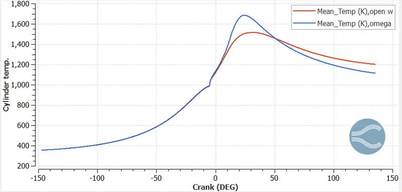
Fig.27 Cylinder temp. vs crank angle
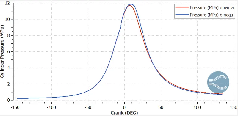
Fig.28 Cylinder Pressure vs crank angle
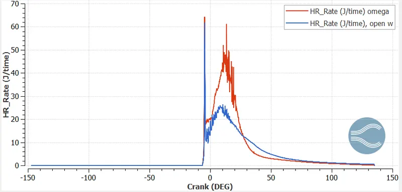
Fig.29 HRR vs crank angle
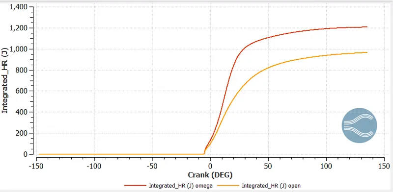
Fig.30 Integrated Heat release vs crank angle
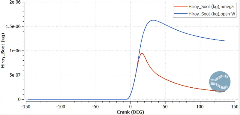
Fig.31 Hiroy soot
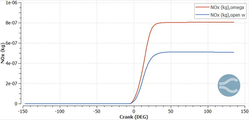
Fig.32 NOx emissions vs crank angle
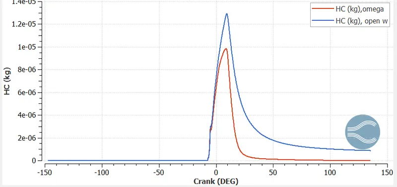
Fig.33 HC emissions vs crank angle
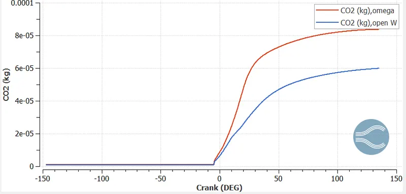
Fig.34 CO2 emissions vs crank angle
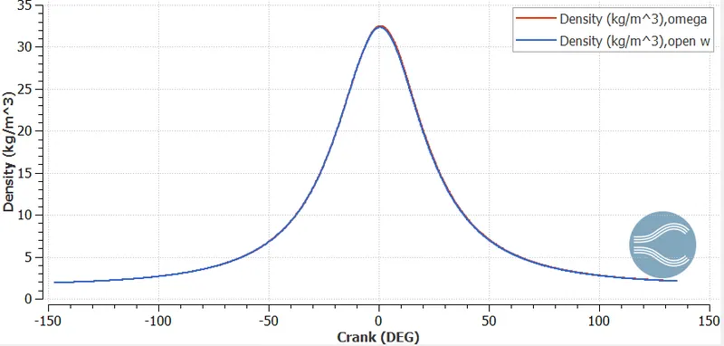
Fig.35 Density vs crank angle
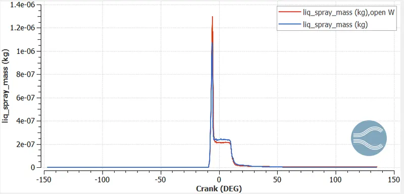
Fig.36 Liquid spray mass vs crank angle
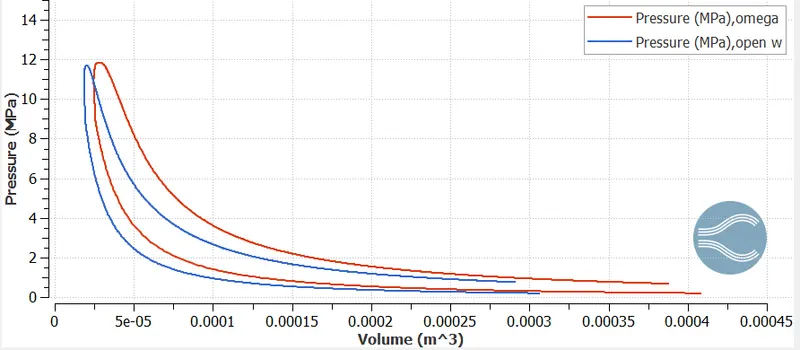
Fig.37 P-V diagram for omega and open-W piston
- We are getting more area under the curve for omega piston,therby producing more workdone.
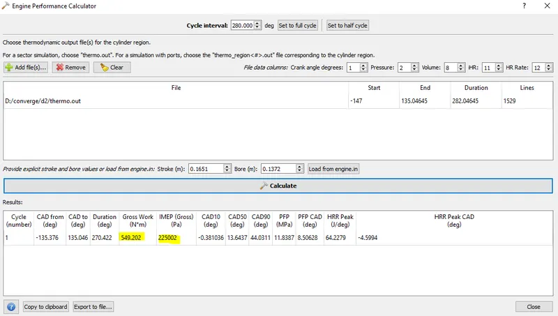
Fig.38 Engine performance of omega piston
Area under PV diagram=Work done(J)
Power= work done*RPM
so,we have rpm=1600 and rps=1600/60
N=1600 rotation/min
=(1600*360)deg/(60 sec)
and we have time in deg. = 270
so, Total time= (270*60)/(1600*360) sec
Now, power= 549.202/(0.028125)= 19.5 KW
If we want to calculate Torque , then `P=(2*pi*N*T)/(60)`
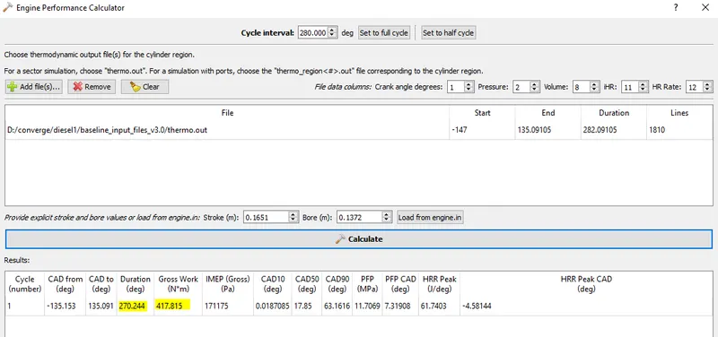
Fig.39 Engine performance of Open W piston
Area under PV diagram=Work done(J)
Power= work done*RPM
so,we have rpm=1600 and rps=1600/60
N=1600 rotation/min
=(1600*360)deg/(60 sec)
and we have time in deg. = 270
so, Total time= (270*60)/(1600*360) sec
Now, power= 417.815/(0.028125)= 14.85 KW
- Soot formation animation omega piston
- NOx formation animation omega piston
- CO2 formation animation omega piston
CONCLUSION
- Emission analysis is being studied by taking two piston profile namely omega and openW.
- Both the pistons are showing results as a tradeoff between performance and emission.
- Omega piston is best suited for performance while openW is best opted for minimizing NOx emissions.
- OpenW piston is somewhat operating in LTC regime. The max. temp. is being in the range of 1200-1800K.
- We are getting max. soot in openW piston ,but it can be minimized in after treatment process.
REFERENCE
- Modelling engine spray and combustion process by Gunnar Stiesch.
- Fundamentals of combustion process by Sara McAllister