Week 11: Project 2 - Emission characterization on a CAT3410 engine
Aim:
- To perform close cycle simulations of CAT3410 engine with two different bowl profiles.
- To study the emissions characteristics of the aforementioned engines.
Objectives:
- Generate the engine sector surfaces by using the 'open w' and 'omega' bowl profiles.
- Provide a brief theoritical introduction to Caterpillar Engine and and close cycle analysis
- Setup the input files for both the engine surfaces.
- Post process the simulation results using CONVERGE Studio and Paraview
Surface Preparation:
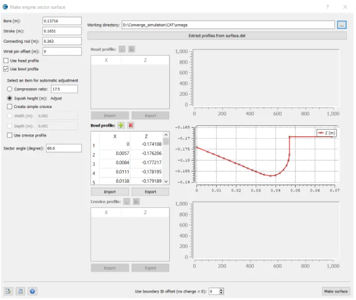
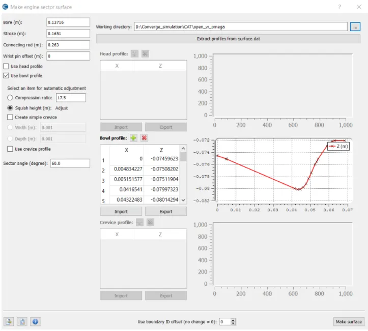
For the current study to generate the engine profiles, we use the inbuilt feature "Make Engine Sector Surface" of the CONVERGE Studio. By providing the inputs for the bore, stroke, conneting rod, compression ratio, sector angle and the custom bore profile we generate the engine surface for both the cases. For the 'open w' engine we extract the bore profile from the available surface.dat file while for the 'omega' engine custom bore profile is used. The settings and their corresponding values for the engine sector surface is depicted in the following figures
Omega bore profile:
Open w bore profile:
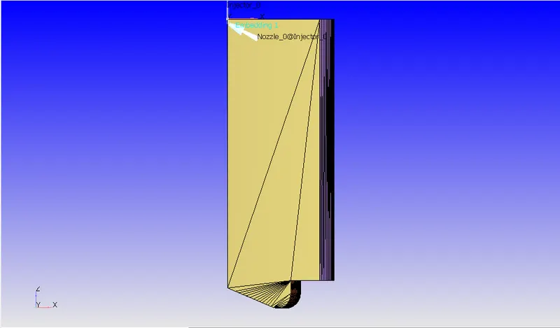
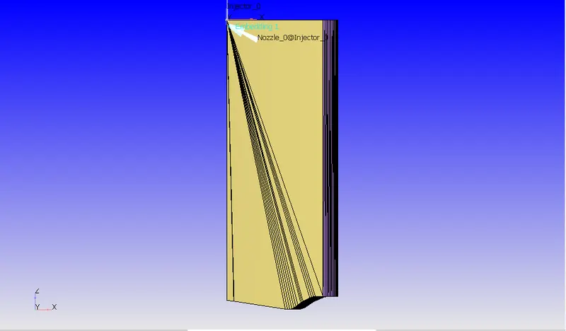
The images for the surface generated from the above settings are as follows
Omega bore profile:
Open w bore profile:
Theory:
Caterpillar 3410 engine is used in the industry because of its large power producing capacity. Simulation of such engines is generally infeasible as large amounts of computational power and long computational times required. To mitigate this, we perform close cycle analysis. In such analysis, we just study the combustion stroke of the IC Engine with the valves of the cylinder head closed. We can also exploit the symmetry of the IC engine and thus simulate just a sector of the engine with appropriate periodic boundary conditions. These simplifications helps us to perform performance and emissions metrics study using only limited computational resources.
In the current study, all the above mentioned symmetry exploiting techniques are exploited.
Case Setup:
To understand and compare the effects of the emissions due to the bowl profile of the piston, both the surfaces are provided with identical boundary and initial conditions. Thus, we will just cover the case setup for the 'open w' engine and provide the same settings for the 'omega engine'.
The case setup tree is provided the following settings:
- Application type: A crank angle based application was chosen for this study due to the nature of the geometry
- Materials:
- The gas simulation of air is used with the default settings for the nature of the gas.
- The diesel fuel is simulated using the parcel simulation and the thermodynamic and physical data for the fuel is used from the default data from CONVERGE.
- The global transport parameters are set to default values.
- The reaction mechanism is set by using custom mech.dat file.
- The gas species are already mentioned in the mech.dat file and only the parcel species and internal passive species (emission products) are tracked.
- Simulation parameters:
- The solver is transient in which the temporal terms are based on crank angle based engine simulation and the simulation mode is full hydrodynamic. The gas flow solver is compressible while the liquid flow solver is incompressible.
- The start time of the simulation is -147 deg and the end time is 135 deg. The time steppping is set to variable which is dependent on the convection CFL number which is set to 1 based on the CFL criteria.
- The Navier Stokes solver is a PISO density based solver with the default settings.
- Boundary
- Piston: Translating, moving wall and law of the wall for velocity and law of the wall with wall temperature as 553K. The tke is set to zero normal gradient and the eps is solved using a wall model.
- Front face: Periodic, stationary and rotational with the angle as 60 degrees. The matching boudnary is set to back face
- Back face: Perodic boundary condition matched with the front face.
- Cylinder wall: Stationary, fixed wall and law of the wall for velocity and law of the wall with wall temperature as 433K. The tke is set to zero normal gradient and the eps is solved using a wall model.
- Cylinder head: Stationary, fixed wall and law of the wall for velocity and law of the wall with wall temperature as 523K. The tke is set to zero normal gradient and the eps is solved using a wall model.
- Initial Conditions and events
- The engine sector is initialized with temperature at 355K and pressure value of 197000 Pa. The species of CO2, H2O, N2, O2 are initialized with the their proportions in the standard air and are stationary in the region
- Physical Models
- Spray Modelling
- The particles are clustered near the center of the cone and the turbulent dispersion is set to O'Rourke Model. The evaporation model is chosen as the Frossling Model. Default settings are used for the penetration and Mass diffusivity constant.
- The collision model is the NTC Collisionand the drop drag model is the dynamic drop drag model with default settings
- We have a single nozzle injector as we are only simulating the sector of the engine. The Kelvin-Hlemholtz and Rayleigh Taylor models are used to mimic the instability in the spray. The rate profile of the provided by the rate_shape.in file is as follows:
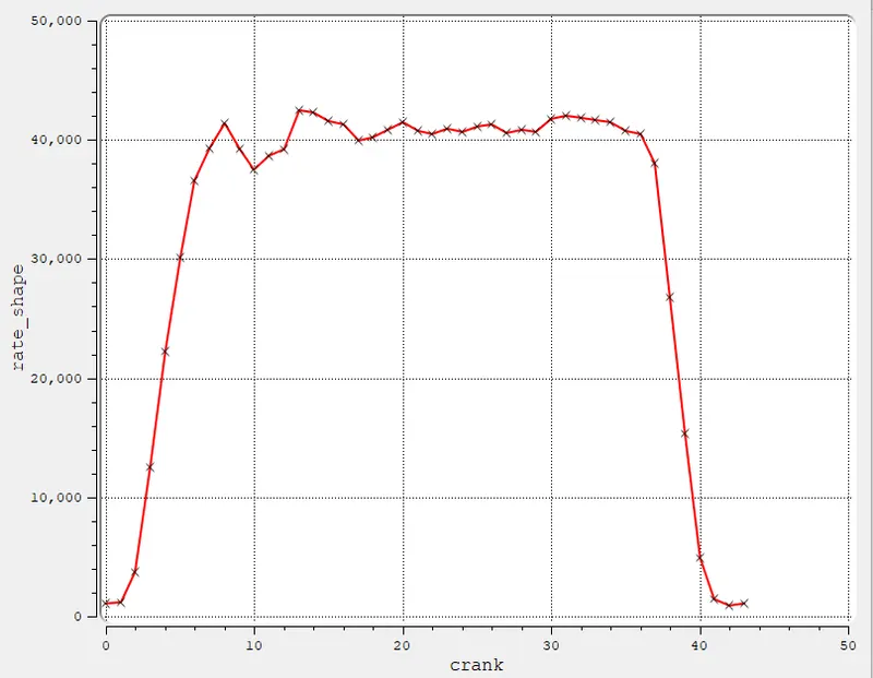
- The injection of the spray starts from -9.0 deg and lasts for 21 deg. The total mass injected in the domain is ~ 27 microkilograms of the fuel. The temperature of the fuel is 341K.
- The nozzle diameter is 0.000259 m and the circular injection radius is half of the nozzle diameter. The spray cone angle is 9.0 deg.
- Combustion Modelling
- The combustion model is active from -10 degrees (before the spray is injected) and is active for the rest of the close cycle analysis
- SAGE detailed chemistry solver is used with the default settings for the current study
- Extended Zeldovich model for NOx is used with equilibrium assumptions and Hiroyasu-NSC soot model with default setting is used.
- For the turbulence modelling, we use the standard RNG k-eps model with wall heat transfer model as O'Rourke and Amsden and near wall treatment as Standard wall function
- Spray Modelling
- Grid Control
- Base Grid is set 0.004 m in all the principal directions
- An adaptive mesh refinement is done in the the engine sector region based on the velocity and temperature. the maximum embedding level is set to 2
- Two fixed boundary embedding at the cylinder head and the piston is provided such that the during the combustion the AMR can be done with sufficient accuracy. One fixed embedding is provided at the nozzle for the same reason and it starts just before the combustion and ends after the spraying of the fuel is completed.
Simulation Results:
Before diving into the results, we will observe the mesh generation animation for both the engines : Animation Link
Volume Average Mean Pressure for open w and omega engines with respect to crank angle:
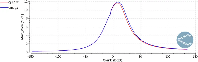
From the above graph, we observe that pressure variation before the spary and combustion is identical but omega engine performs slightly better with a peak pressure of 11.8 MPa compared to the peak pressure of 11.6 MPa of the open w engine
Volume Average Mean temperature for open w and omega engines with respect to crank angle:
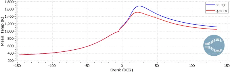
Similar to the pressure curve, the open w and omega piston have identical behavior before combustion. After combustion, the mean temperature of the omega piston engine is significantly higher than that of the open w piston engine. The max mean temperature of the omega piston is ~1680 K while the open w piston is ~1510 K
Integrated Heat Release for open w and omega engines with respect to crank angle:
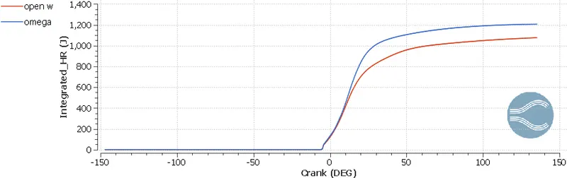
Because of the better fuel consumption by the omega engine, the integrated heat release rate is consequently higher than its counterpart. After the end of the simulation, the integrated heat release from the omega piston is ~1206 J while the value for the open w piston engine is ~1076 J. The difference of the integrated heat release between them is ~130 J.
Using the formula of the combustion efficiency which is represented mathematically as follows
`eta_c = {I.H.R}/{m_f times C.V}`
the `m_f` is the mass of the fuel = `2.70167 times 10^{-5}\ kg` and the calorific value of C7H16 = `48.06\ {MJ}/{kg}`
Substituting these values in the above equation, we get
`eta_c = 0.9288` for the omega engine and `eta_c = 0.8287` for the open w engine
Engine Parameters for the omega and open w engine
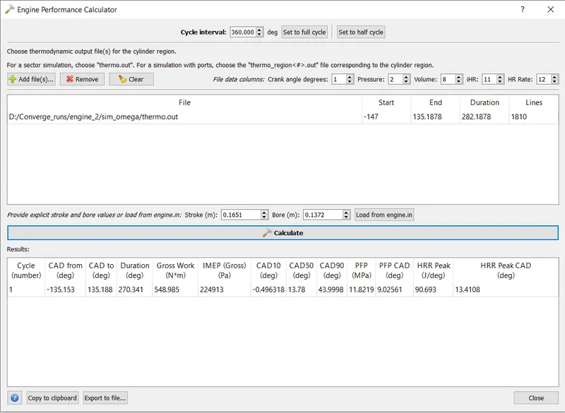
Omega Piston
Open w piston
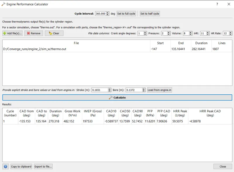
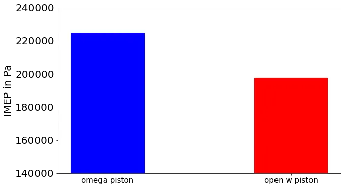
The indicated mean effective pressure is a constant pressure acts on the piston head. It is a measure of the work output we get for displacing the volume of engine. It is an important parameter for determining the efficiency of an engine.Comparing them visually in the following bar plot we get
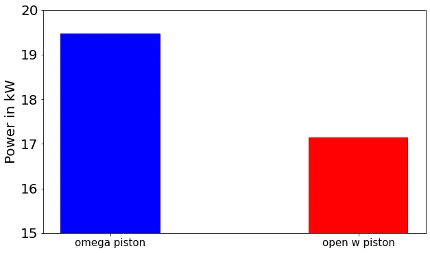
The mathematical formula for the power generation is as follows
`P = W/t`
For the omega piston engine,
`W = 548.985\ Nm` and `t = {60 times 270.349 }/{1600 times 360} = 0.0282\ s`
`P = 548.985/0.0282 = 19.47\ kW`
For the open w piston engine,
`W = 482.152\ Nm` and `t = {60 times 270.318 }/{1600 times 360} = 0.0282\ s`
`P = 482.152/0.0282 = 17.14\ kW`
Emissions of omega and open w engine with respect to crank angle
- CO
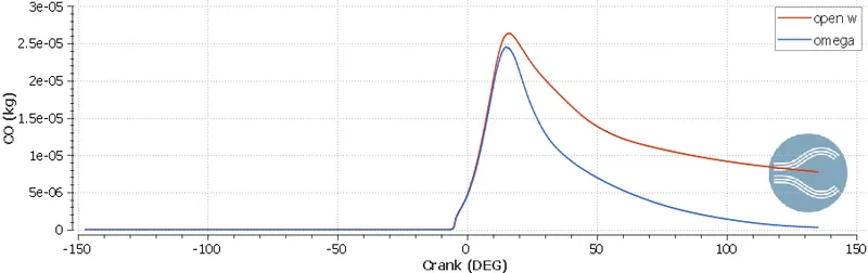
We can observe that the CO emissions are significantly higher (almost by order of magnitude) in the open w piston engine compared to omega piston engine. This is expected because of the delayed combustion of the fuel
- CO2
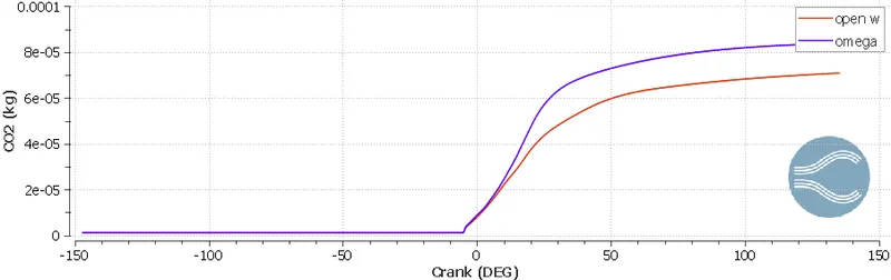
The CO2 emissions are higher in the omega piston engine compared to the open w engine because of the higher amount of consumption of the fuel by the omega piston engine
- NOX
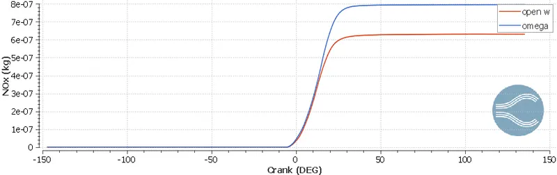
Similar to CO2, the NOX emissions are higher in the omega piston engine because of them higher temperature in the region due to better consumption of the fuel during consumption
Animation of the cut plane of NOX emissions for both the geometries: Animation Link
- Hiroy soot
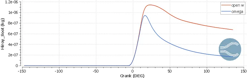
The amount of soot is three times higher in the open w piston engine compared to the omega piston engine at the end of the simulation.
- HC
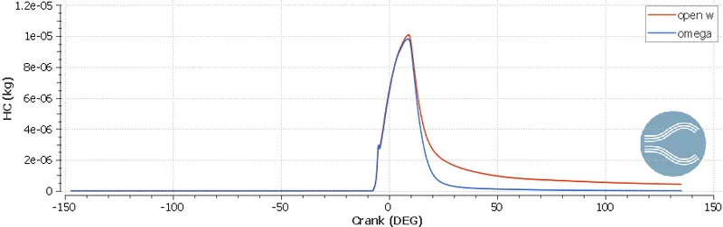
The amount of HC emissions are slightly higher because of the incomplete combustion of the fuel in the open w piston engine.
Conclusions:
We have successfully simulated engine sector with two different bore profiles namely 'open w' and 'omega'. The case setup for both of the surfaces are explained in detail. The simulation results are post processed in CONVERGE Studio and Paraview. From the analysis we can conclude that for current configuration, the omega piston engine has superior performance metrics but has higher emissions of NOX and CO2.