week-11 Joint creation and Demonstration
Aim:demonstrate spherical, revolute, cylindrical, and translational joints between two rigid bodies and two deformable bodies.
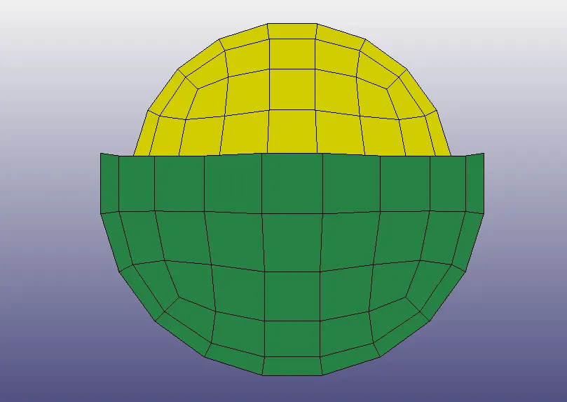
2. Revolute joint
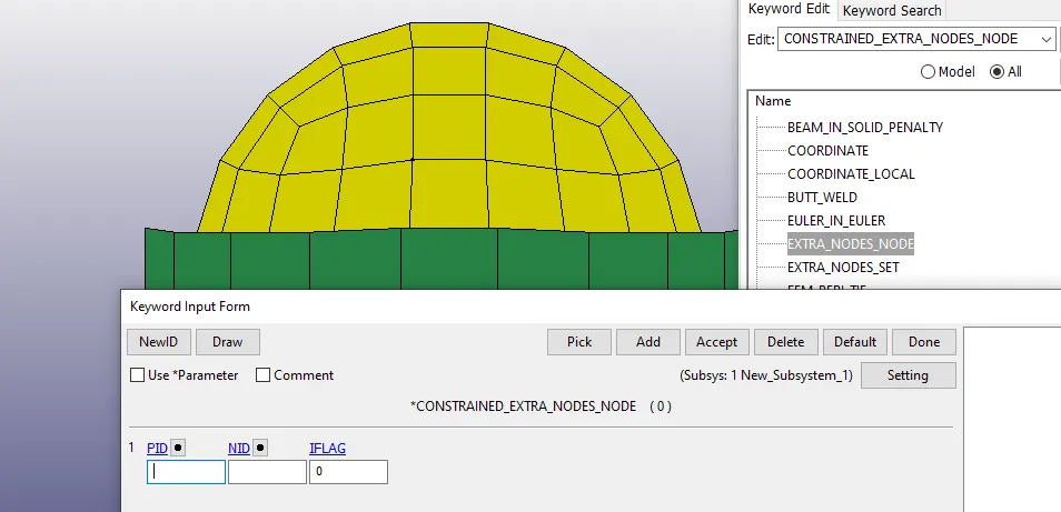
- Two pairs of nodes are created for constraining, using Node edit option under Element Tools. The nodes 101, 102 are constrained to part 1 and 103,104 to part 2 respectively, using CONSTRAINED_EXTRA_NODES card. as shown below.
- A revolute joint is then created between them, using the CONSTRAINED_JOINT menu, using nodes 101 and 102 of part 1 and103,104 of part 2.
- The material and section properties are the same as that of the spherical joint.
- Now here Part 1 (red) is fixed, and part 2 (blue) is the moving part. The part 1 is fixed with SPC's at all nodes, in order to prevent motion, and a prescribed motion is given to part 2, as shown below.
- Here we have defined the curve for motion set from define curve option.
3. Cylindrical Joint.
- The material and section properties are the same as that of the spherical joint.
- Now two pairs of nodes are created for constraining, using Node edit option under Element Tools. The nodes 321, 323 are constrained to part 1 and 322,324 to part 2 respectively, using CONSTRAINED_EXTRA_NODES card, as shown below.
- A cylindrical joint is then created between them, using the CONSTRAINED_JOINT menu, using nodes N1 and N3 of part 1 and N2,N4 of part 2.
4. Translational Joint
- Now we will check the model for errors and run the simulation.
B. Joints between deformable bodies
2. Revolute joint
3. Cylindrical Joint
4.Translational Joint