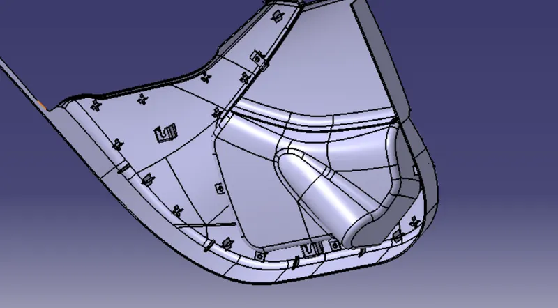
Week 11 - Final project
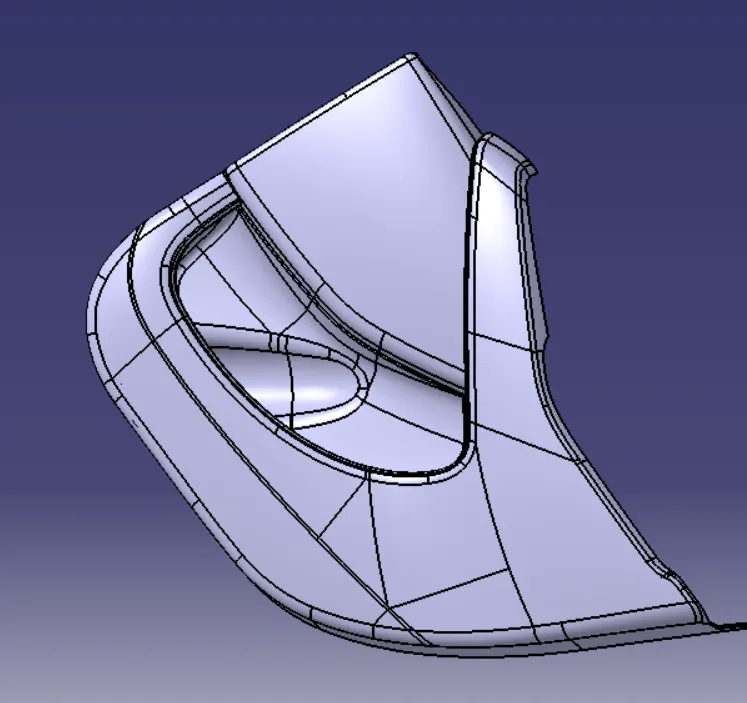
Aim:- To design car door inner plastic trim along with engineering features with respect to provided class-A surface and according to design standards.
Procedure:- There are four different parts included in door inner trim, namely
- Lower substrate
- Map pocket
- Bottle holder
- Arm rest
Same procedure is follow to design plastic trim for all four components. Which as follows:-
- Check for continuity of given class-A
- Analyse class-A by draft analysis of minimum 3degree of angle
- Offset class-A to create class-B according to master section provided. All parts has 2.5mm of thickness.
- C surface is created by sweep command by using boundary of class-A
- Class-A and C surfaces are join togther
- Then joined surfaces trim with extrapolated class-B
- Obtained hollow trim converted into solid
- Then engineering features and flanges are created over solid bodies
- All the engoineering features are provided with minimum draft requirement
- Again draft analysis is done for solid body created
Following are 4 different parts:-
1. Lower Substrate:-
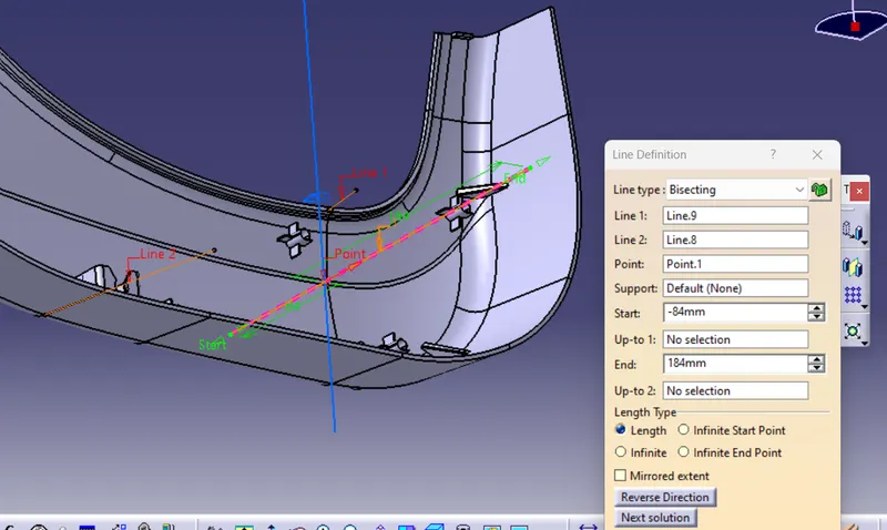
Tooling axis creation
It is created by bisecting slant edges of class-A
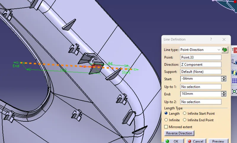
Side core axis
It is created along the open face of dog house
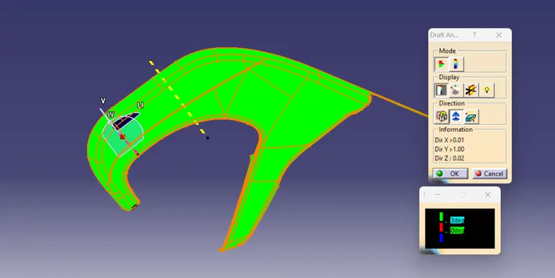
Draft analysis of class-A (3 degree of draft)
Draft analysis of solid body (3 degree of draft)
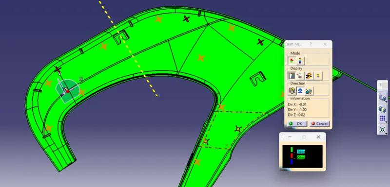
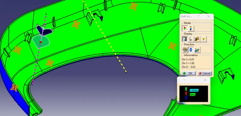
Draft analysis of solid body (1.5 degrees draft for engineering features)
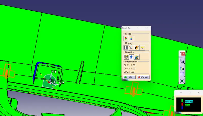
Draft analysis of solid body (0.5 degrees draft for dog house according to side core axis)
Different view of solid
Side view
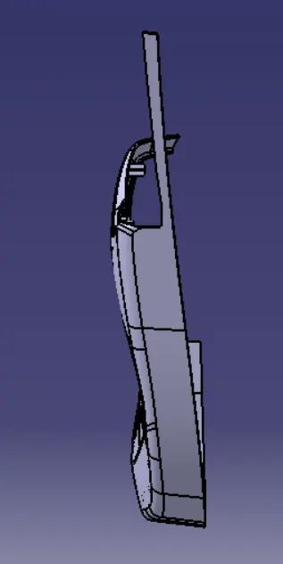
FRont view
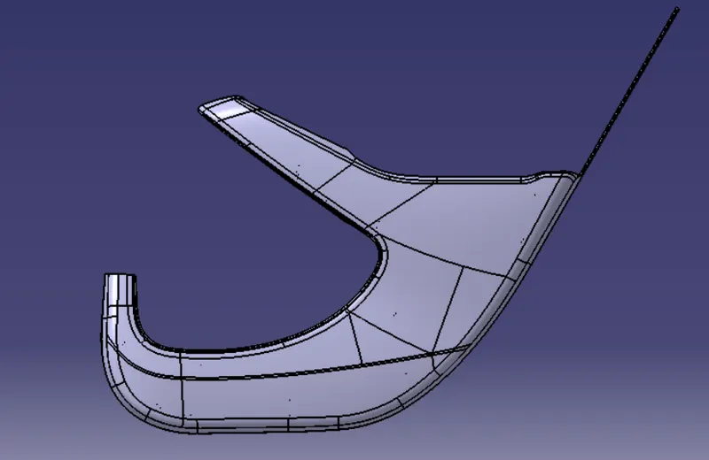
Rear view
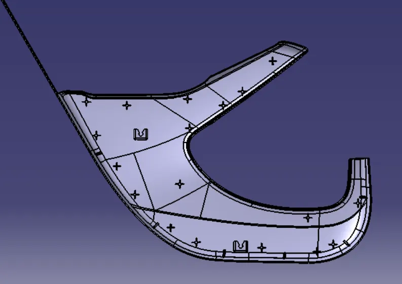
Top view
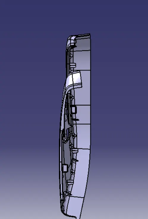
Iso view
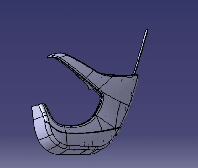
2. Map Pocket
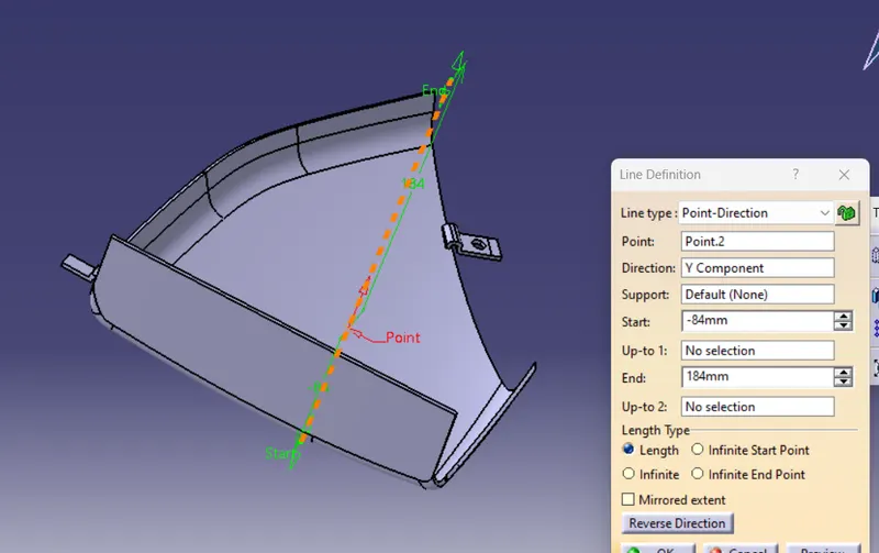
Tooling axis creation
It is created perpendicular to surface of map pocket
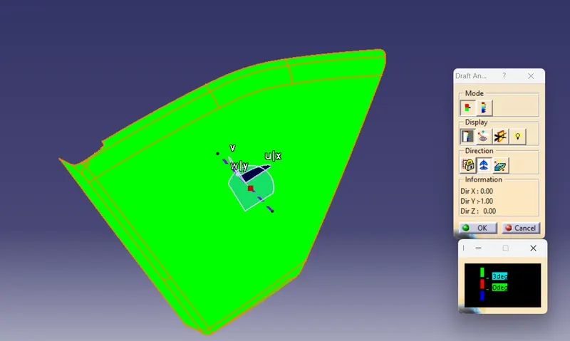
Draft analysis of class-A (3 degree of draft)
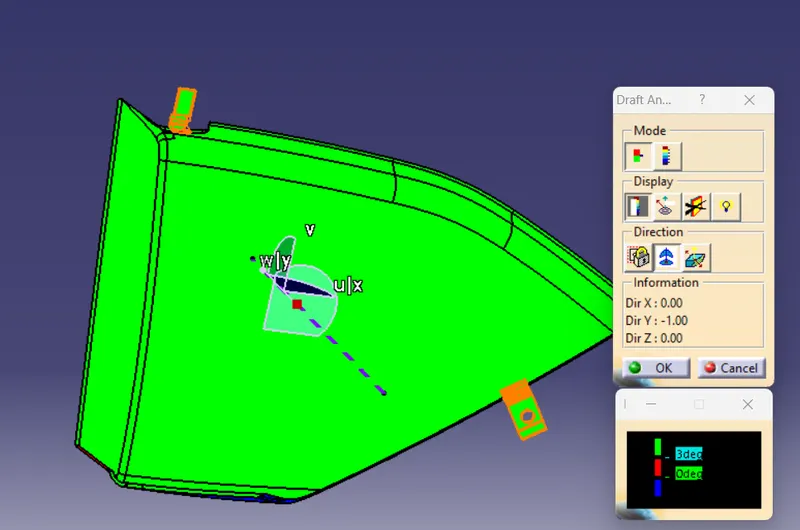
Draft analysis of solid body (3 degree of draft)
Different view of solid
Side view
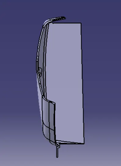
Front view
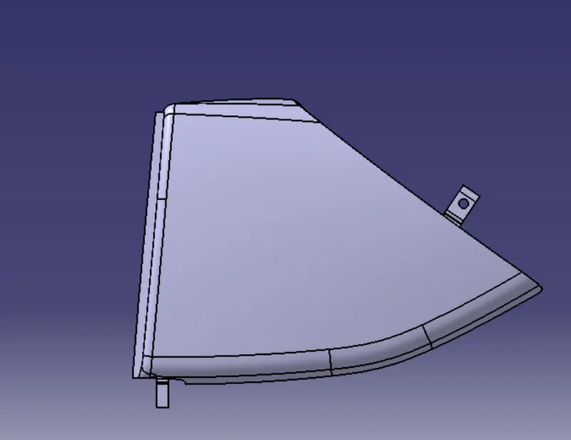
Top view
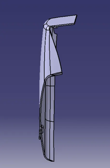
Iso view
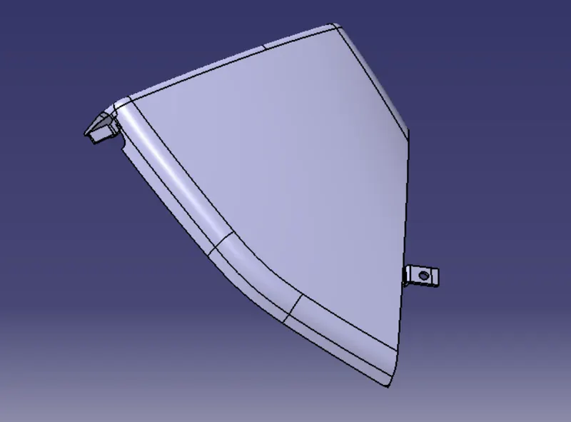
3. Bottle Holder
Tooling axis creation
It is created by bisecting method. All four faces are use for creation of tooling axis.
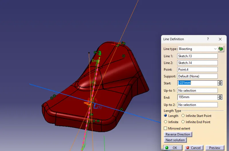
Draft analysis of class-A (3 degree of draft)
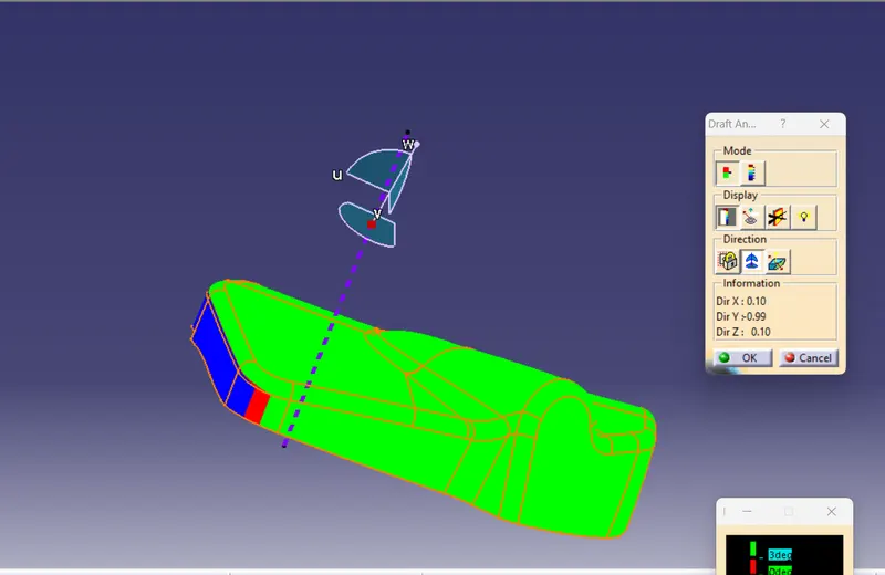
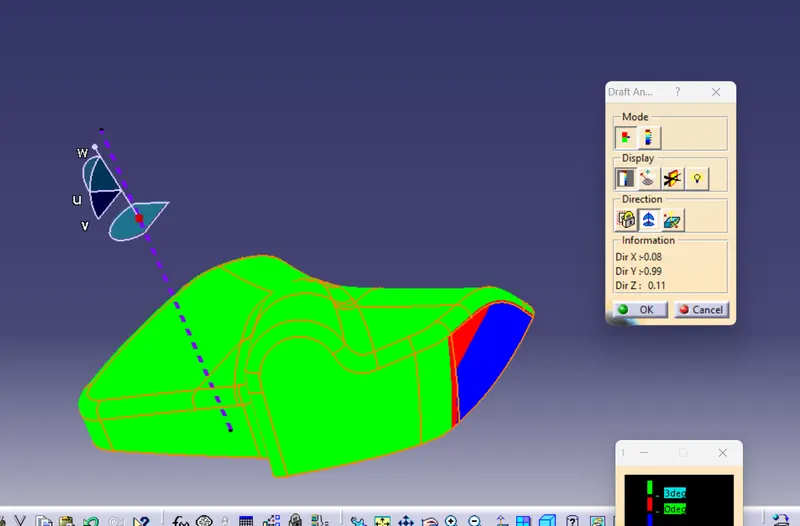
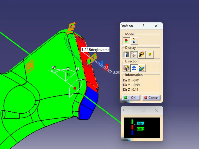
Given class-A does not pass the draft analysis of minimum 3degrees. Some part of the given class -A does not shows green. Hence diffrent positions of axis is taken by rotating co-ordinate system to check for any possibility of passing whole class-A in draft analysis.
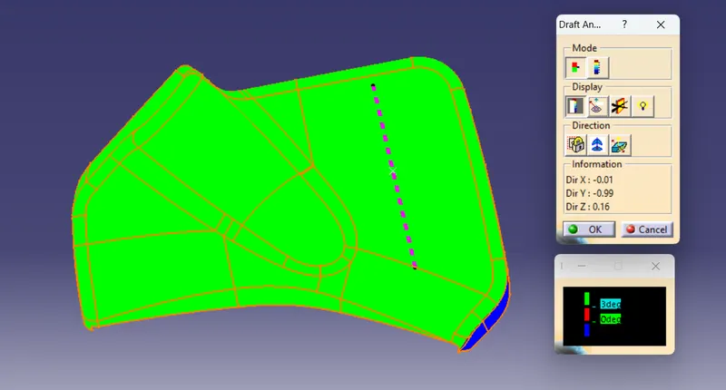
But even by checking for another tooling axis, some or other surface of class-A fails during draft analysis.
Following are different tried positions of co-ordinate system while draft analysis
Draft analysis of solid body (3 degree of draft)
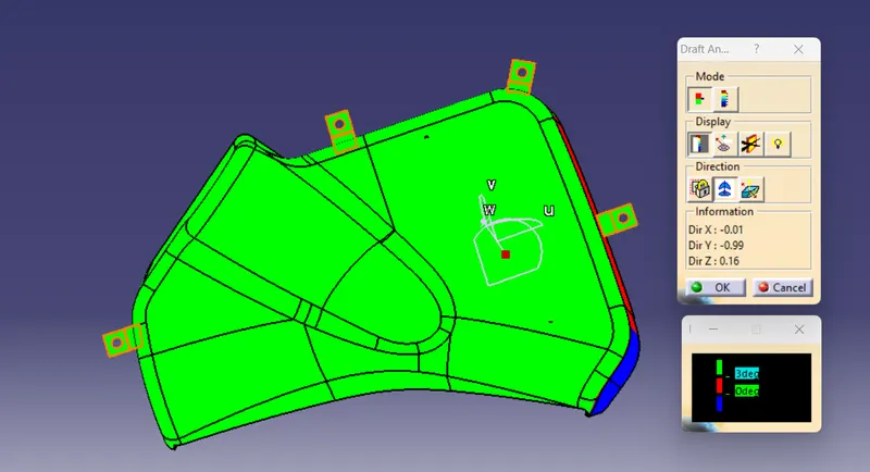
Same error occured during draft analysis of solid body
Different view of solid
Side view
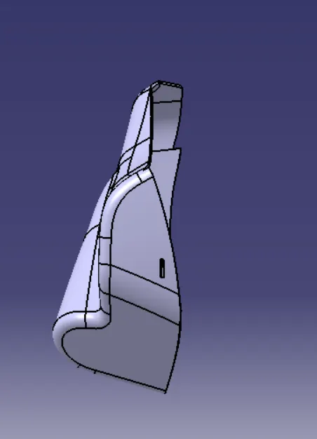
Front view
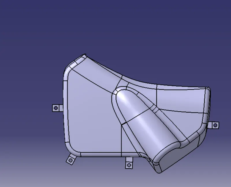
Rear view
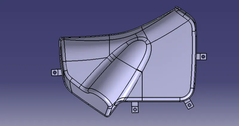
Top view
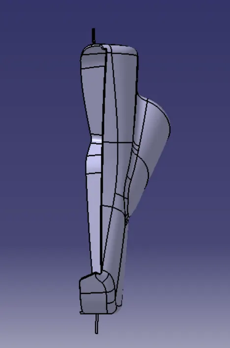
Iso view
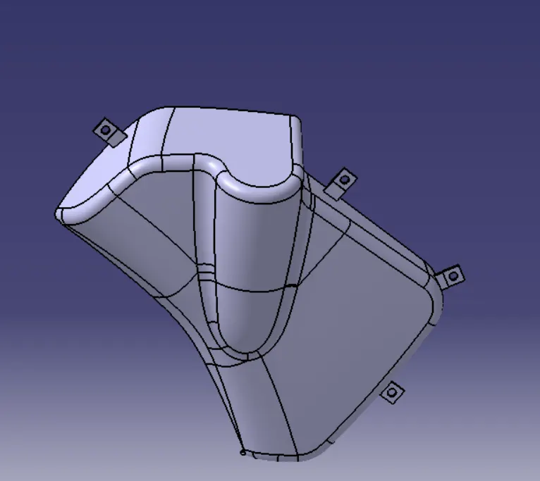
4. Arm Rest
Continuity of class-A
Given class-A was having some dicontinuity. So styling engineering must correct that. Corrected class-A is used for further operations
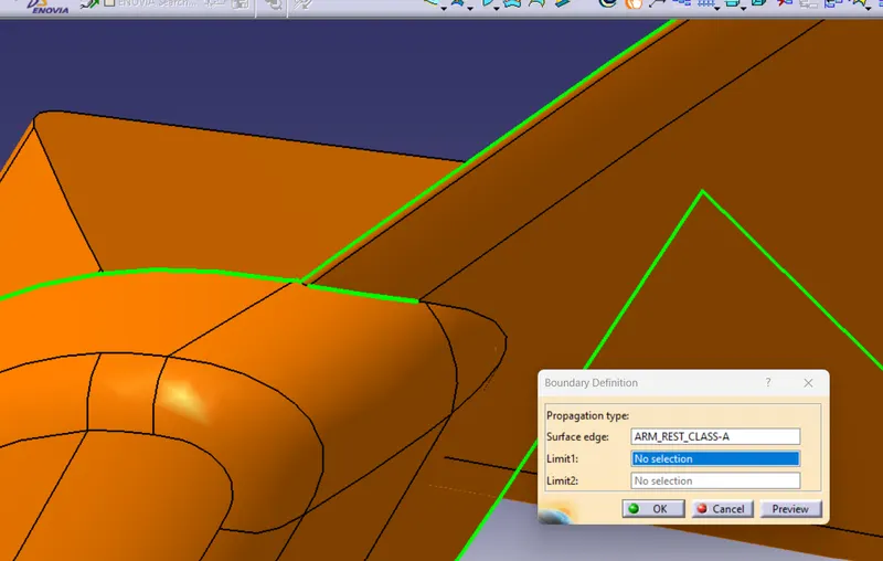
Tooling axis creation
There was undercut like surface which was facing problem in passing draft analysis. So Tolling axis is created by ensuring minimum 3 degree of draft to that surface.
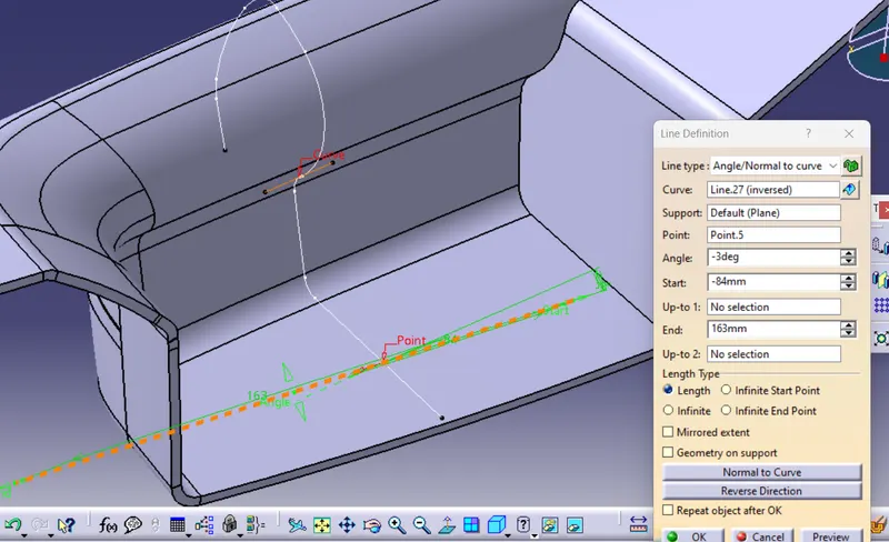
Side core axis
Some part of arm rest was difficult to pass in draft analysis with main tooling axis. So Side coring axis is created

Draft analysis of class-A (3 degree of draft)
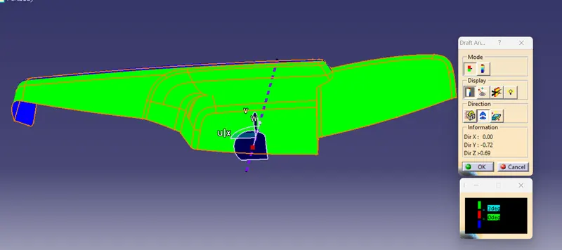
Draft analysis of class-A with respect to side core axis (3 degree of draft)
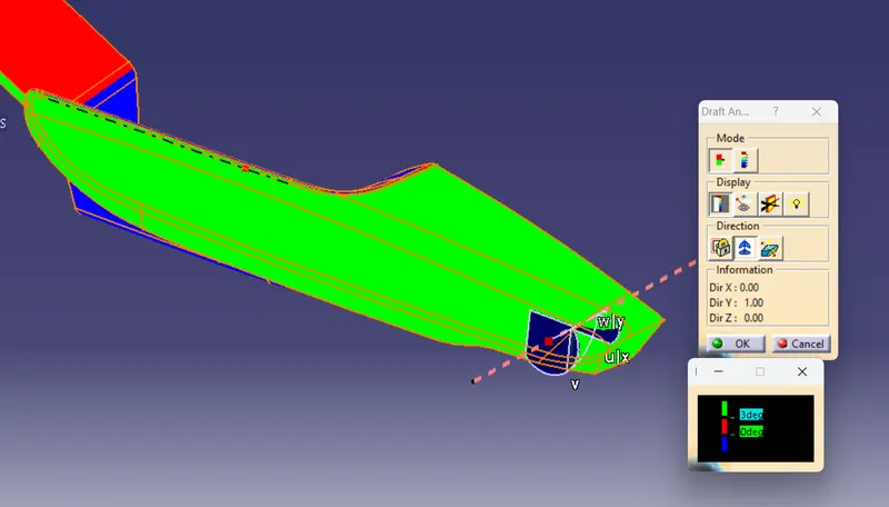
Draft analysis of solid body (3 degree of draft)
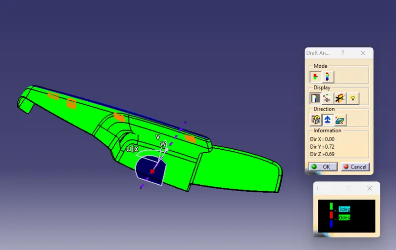
Draft analysis of solid with respect to side core axis (3 degree of draft)
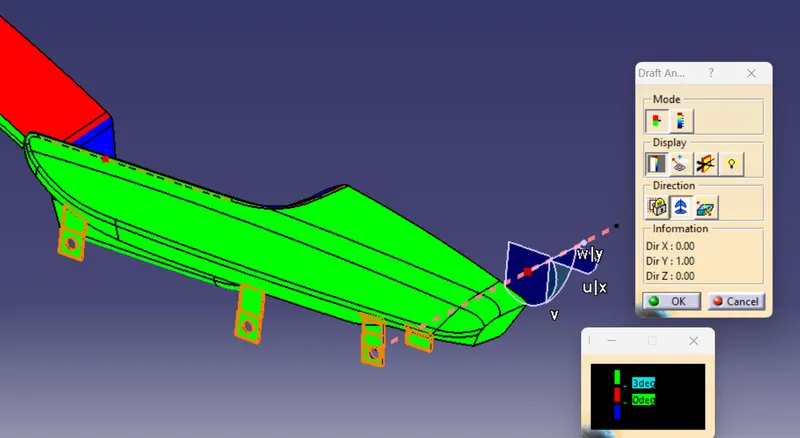
Different view of solid
Side view
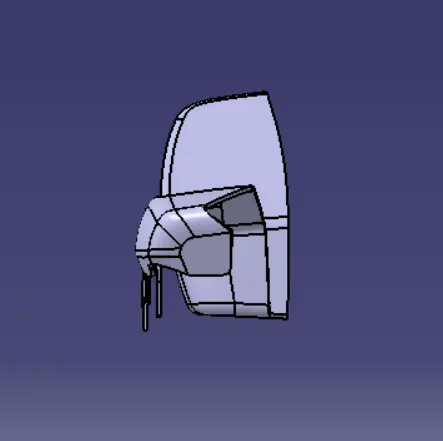
Front view

Rear view
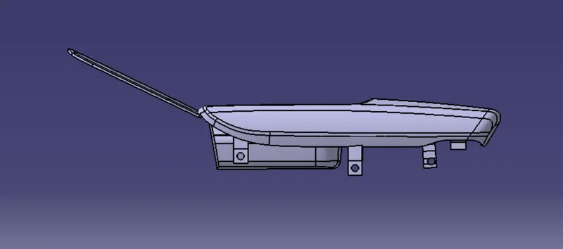
Top view
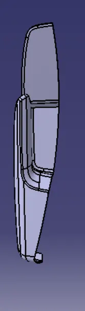
Iso view
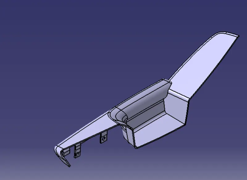
Overall views of Door Inner sold
Side view
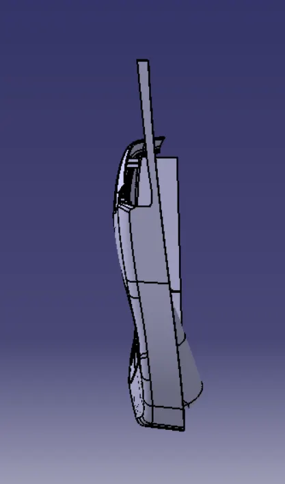
Front view
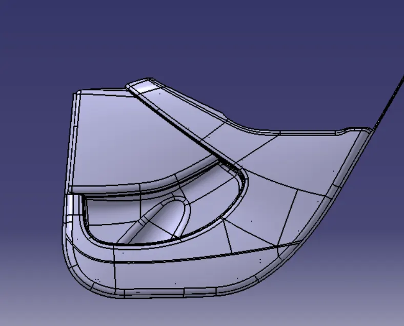
Rear view
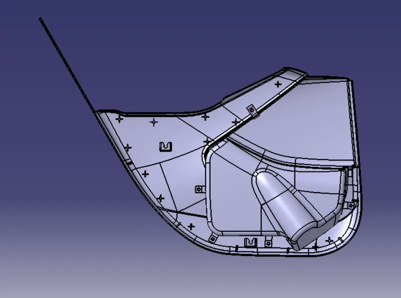
Top view
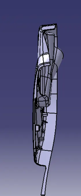
Iso view
Engineering Features