Week 11 - Final project
Week 11-Final Project (Development of a door trim panel)
Objective
The main objective of this project is to design a door trim panel using Catia v5 with given Class A surface along with mastersection.
1)To create individual tooling axis.
2)Creating of Class B and C surface.
3)Closen body and thicken part.
4)Perform draft analysis.
5)Creating of B side engineering features.
6)Assembling of push pin.
Tooling Axis
It is the direction in which mould opens and closes,usually parts are drafted along the tooling direction.
Class A surface
In automotive design a Class-A surface in any of a set of from surface of high efficiency and quality.Class-A surface is creating by using computer Aided digital applications. Class-A surface modellers are also called digital sculptors in the industry.
Class B surface
Class B surface are Engineering Surfaces which are invisible to the eyes or often on the back side of the Class A surface. It is mainly the thickness of the component or Class A.
These surfaces need to be designed as per the Class A surface i.e., the continuity, thickness of the component, functionality etc should be maintained.
These surfaces include the main engineering features such as Screw bosses, Ribs, Snaps, Stiffeners and fixations.
Class C surface
Class C surfaces are connectors between Class A and Class B surfaces. This surface connects both A and B surfaces along the tooling Axis.
It is basically the thickened surface between both A and B surface.
Draft analysis
The Draft Analysis allows the user to easily analyze a part for proper draft angle. A Draft Angle describes the amount of taper for molded or cast parts perpendicular to the parting line.Draft Analysis is applicable for 3D part models.
Components of door trim panel
1)Lower substrate.
2)Door arm rest.
3)Bottle holder.
4)Map pocket.
Lower substrate
Pre-checks
Before starting the creation of the class B surface we must ensure that the given class A surface is properly closed and the surface continuity is proper. This can be done either with the help of the join operation or by using the boundary feature.
Tooling axis
1)In this case extracted surface and created a point.
2)Later on created a line along the Y axis direction.
3)Further created a line along the X axis direction.
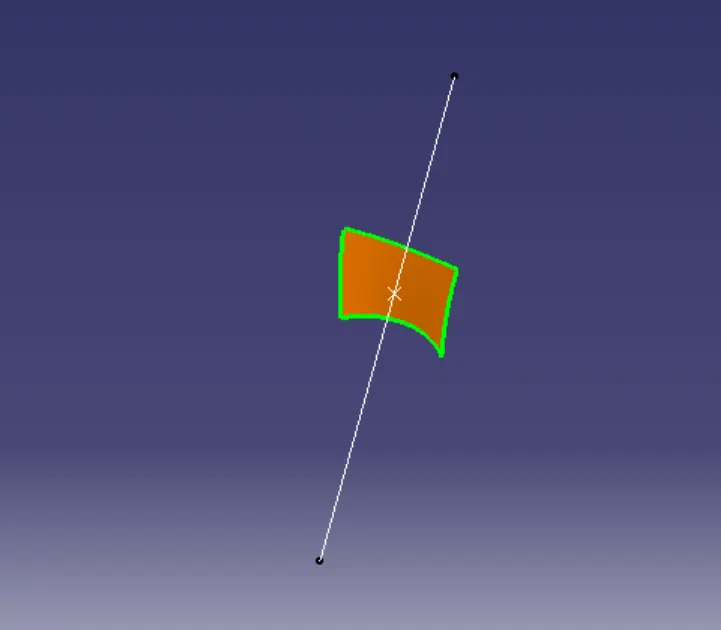
Lifter axis
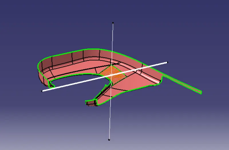
Class B surface
The creation of Class-B surface can be done by smiply offsetting the class-A surface to the required distance, required direction and extrapolated the few edges in it.
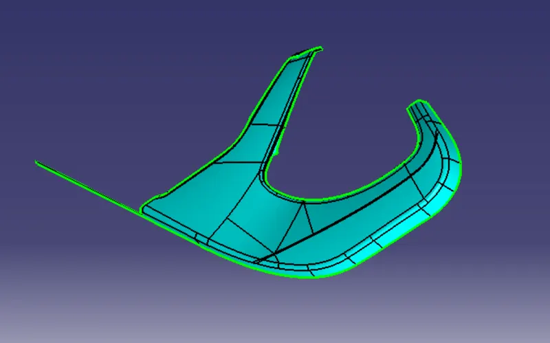
Class C surface
Extracted the edges of Class A using multiple extract and performed sweep operation to the required dimensions.
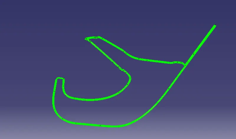
Final part
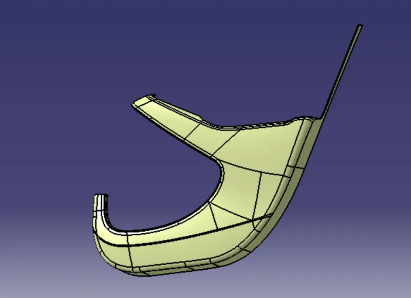
The final trim is created by joining the Class A and C surface and finally trimming it with the Class B surface.
B side features
Dog house
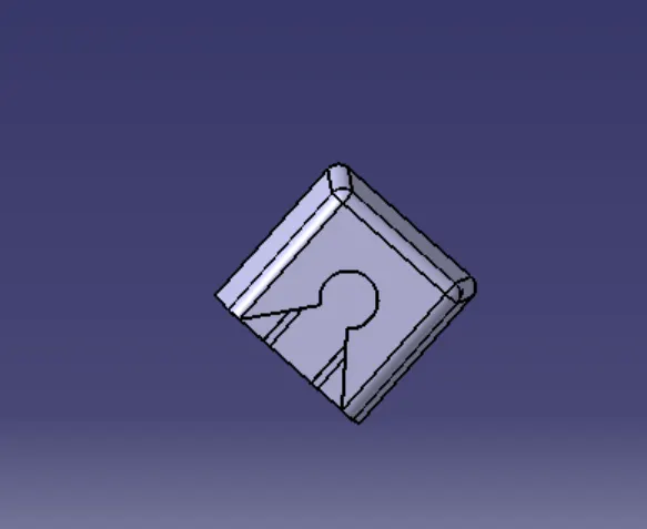
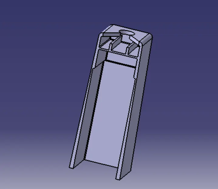
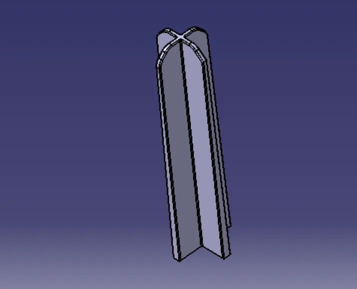
The purpose of a dog house are to avoid sink marks and to house various other engineering features like screw boss, locators, push clips etc.In this case,the dog house is designed to house the push clips.
The dog house designed for the push clip features a slot on the top face to accommodate the push clip.
Design rules
Height should be between 3.0-6.0mm.
Dog house wall thickness should be 40% less than main component.
Draft angle for inner is 0.5 degrees and outer is 3degrees.
Heat stakes
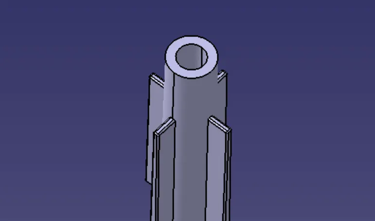
Heat stakes are used in thermoplastics to assemble two parts together by locally heating and cooling the plastic material and allowing it to reform itself and act as a joint for the two materials.
We have placed 8 heat stakes in the model based on the reference points created by estimation.
Locators
1)The main purpose of locators is to facilitate proper locking of two components together while assembling and arrest the maximum degrees of freedom possible.
2)These locators are similar to guide pins provided in mould.
3)We have positioned two 4 way locators in our model which meet the design criteria.
Draft analysis
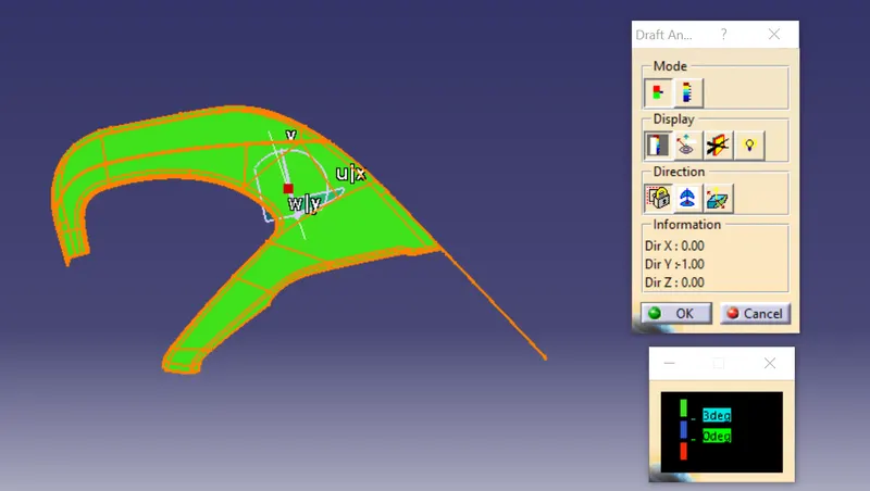
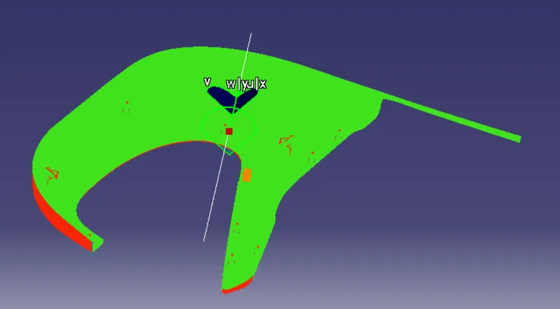
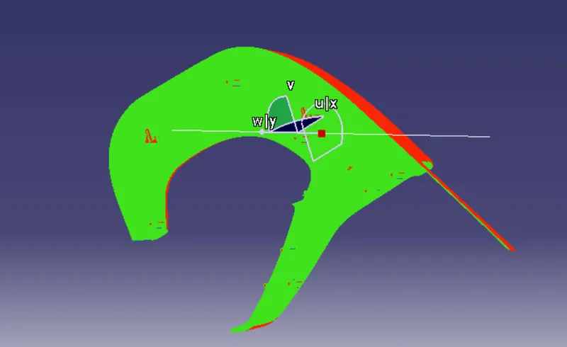
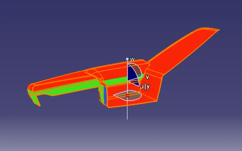
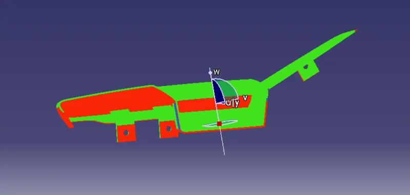
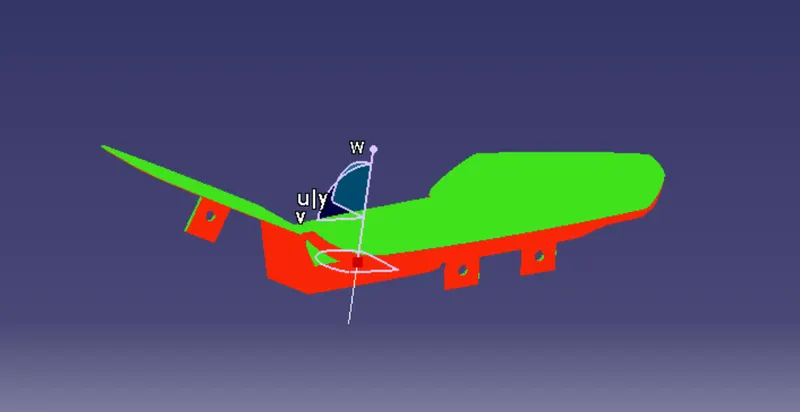
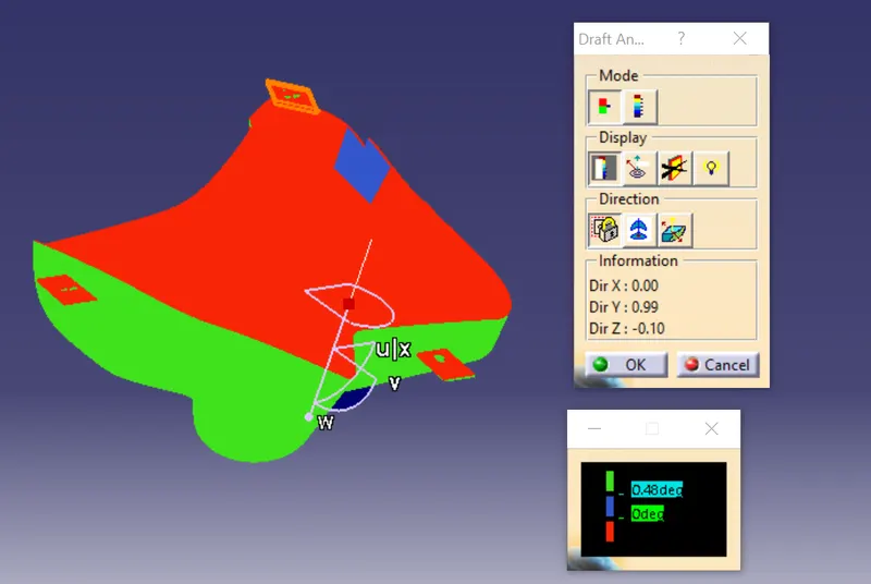
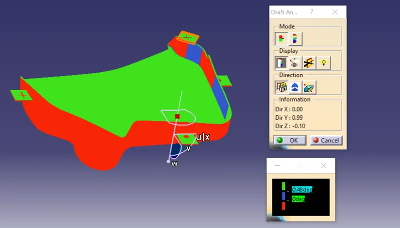
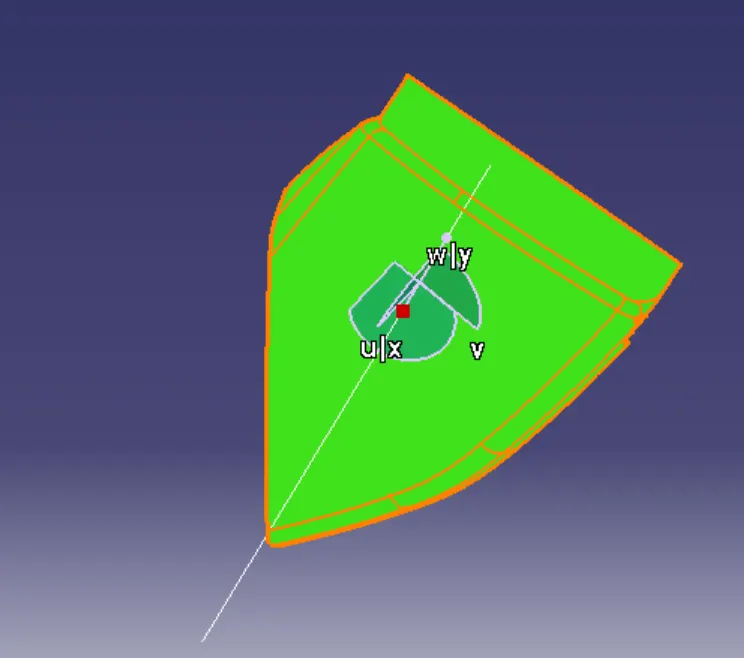
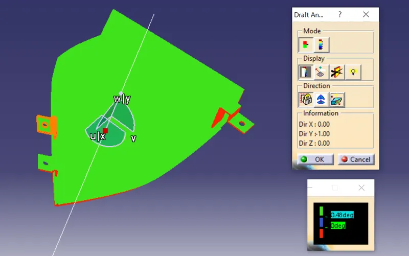
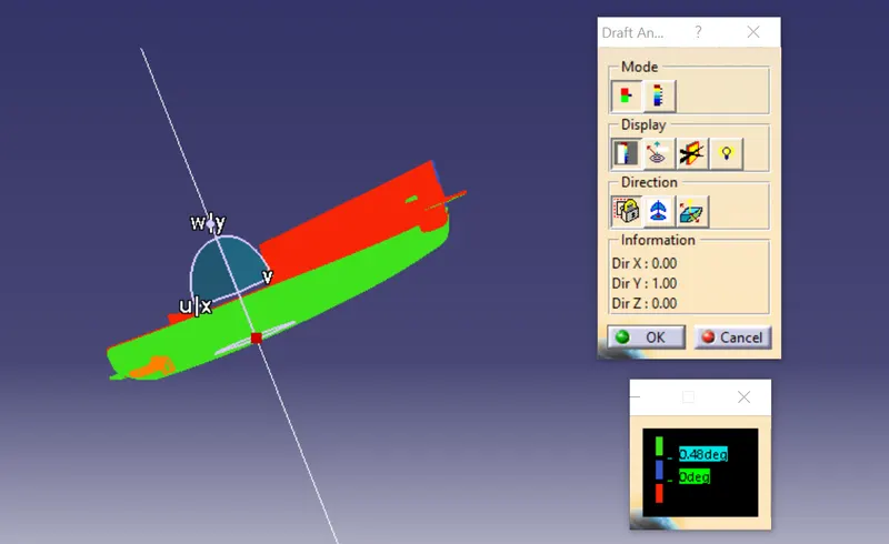
Draft analysis is done on the final part with the tooling axis as reference.Green surface indicates the areas where the draft is more than 0.5 degrees.Red surface indicates the areas having negative draft.
Lifter axis for clearing the dog house inner surfaces are provided for dog house.
Class A
Final model
Lower arm rest
Pre-checks
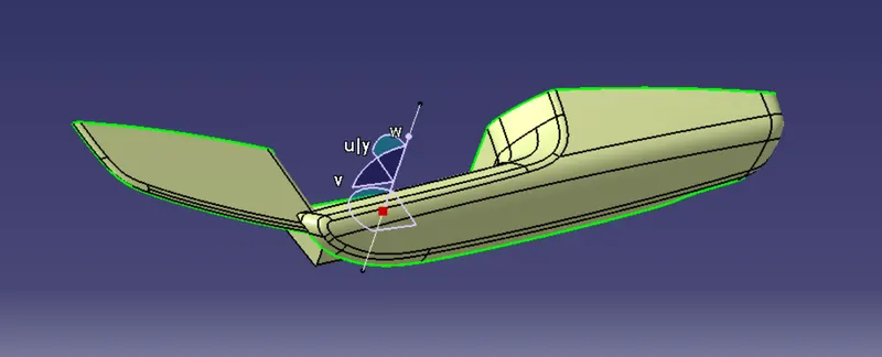
The class A surface of the arm rest received had a small opening near the edges and it is solved by extracting the edges and splitting it.
Tooling axis
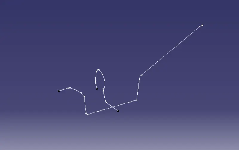
1)Created a point and inserted axis system in it.
2)Created intersection on YZ and XZ planes.
3)Created line along YZ and XZ planes and created tooling axis by bisecting it.
Bisecting method
Class B
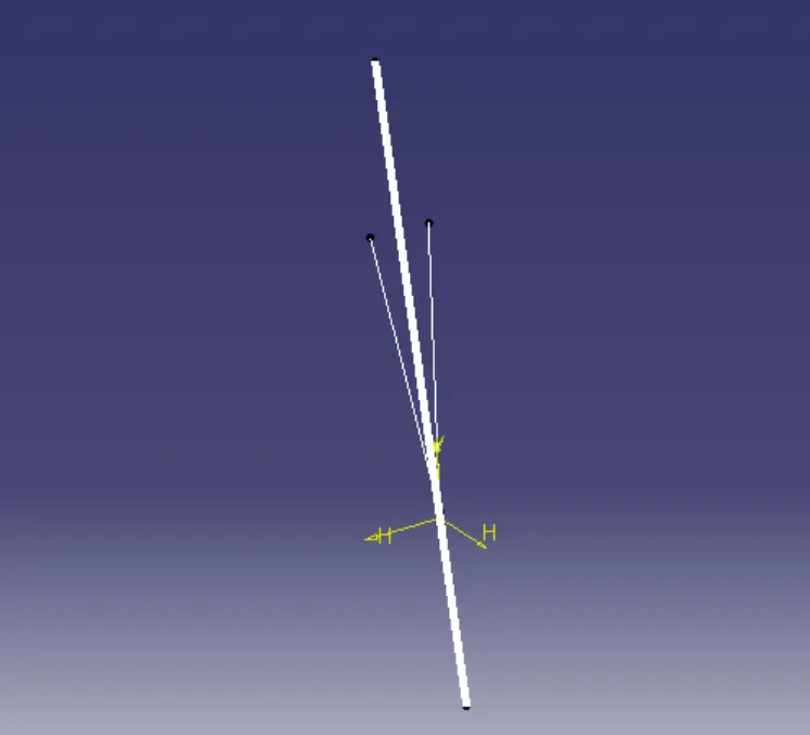
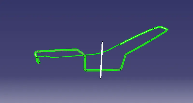
Offsetted the Class A for around 2.5mm and the Class B is created.
Class C
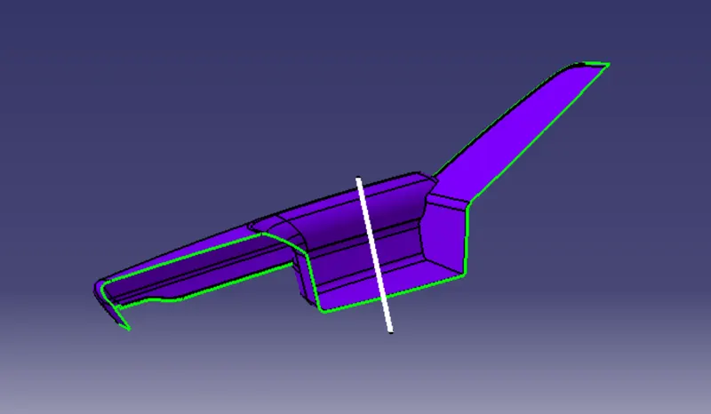
Extract the edges of Class A using multiple extract and sweeped it to the required length,thus Class C is created.
Final
Class A and C is joined,further trimmed with Class B surface.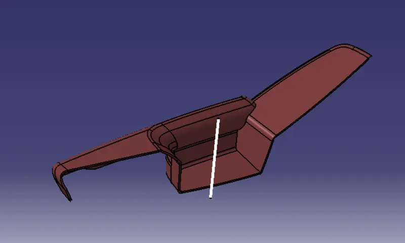
B side engineering features
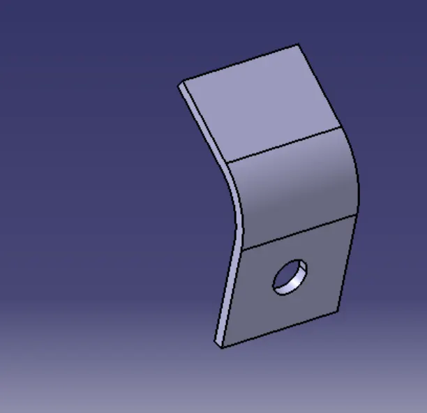
The purpose of the flange was to provide slots for the heat stakes which are required to assemble the two components together and constraint the motion between them.
Draft analysis
Class A
Final
Bottle holder
Pre-checks
The class A surface provided for the map pocket bottle holder was checked for openings with the aid of boundary feature. There were no openings found in the class A surface.
Tooling axis
1)Extracted the surface and created a point.
2)Created a intersections on XY and YZ planes.
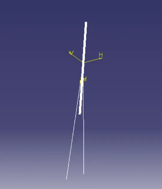
3)Created tooling axis by bisecting the two lines which is created by using two planes.
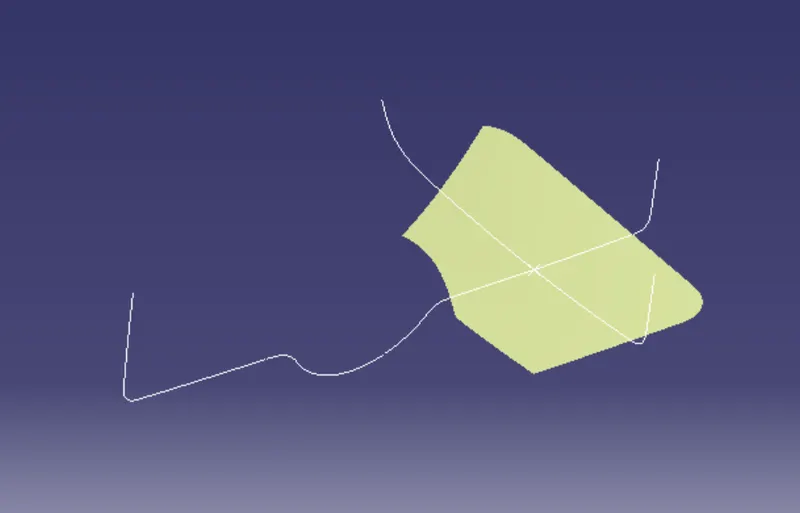
Bisecting method
Class B
The creation of class-B surface can be done by smiply offsetting the class-A surface to the required distance and required direction.
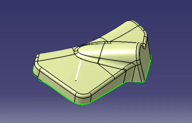
Class C
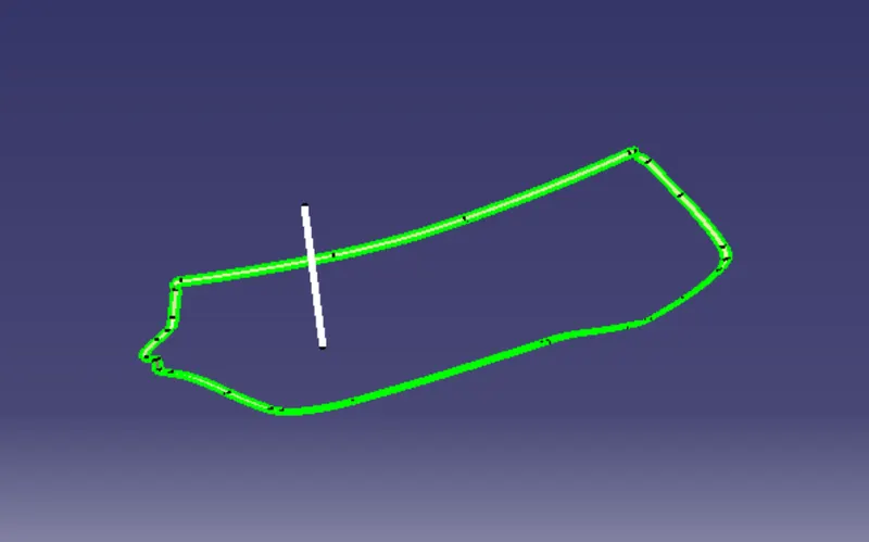
Extract Class A boundary and convert to Smooth Curve.Sweep value should be greater than the Thickness required for part.
Final
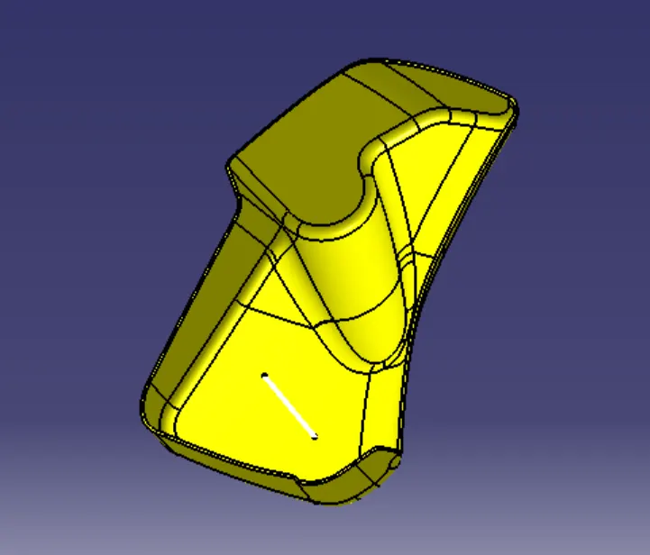
Class A and C is joined,further trimmed with Class B surface.
Engineering features
Flange
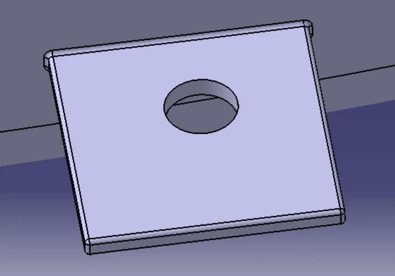
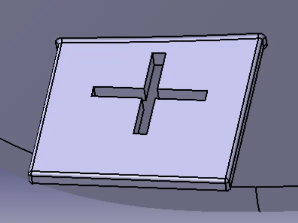
Flanges were creted along the surface of the map pocket bottom holder. The purpose of the flange was to provide slots for the heat stakes and locator which are required to assemble the two components together and constraint the motion between them.
Draft analysis
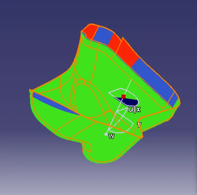
Class A
Final
Map pocket
Pre-checks
The class A surface provided for the map pocket bottle holder was checked for openings with the aid of boundary feature. There were no openings found in the class A surface.
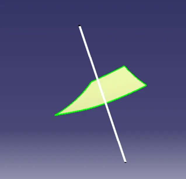
Tooling axis
1)Extracted the surface and created a point.
2)Created a line along the Y axis direction and tooling axis is formed.
Class B
The creation of class-B surface can be done by smiply offsetting the class-A surface to the required distance and required direction.
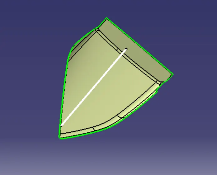
Class C
1)Extract Class A boundary.
2)Sweep the curve to the Class A.
3)Sweep value should be greater than the Thickness required for part.
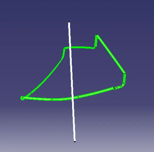
Final
Class A and C is joined,further trimmed with Class B surface.
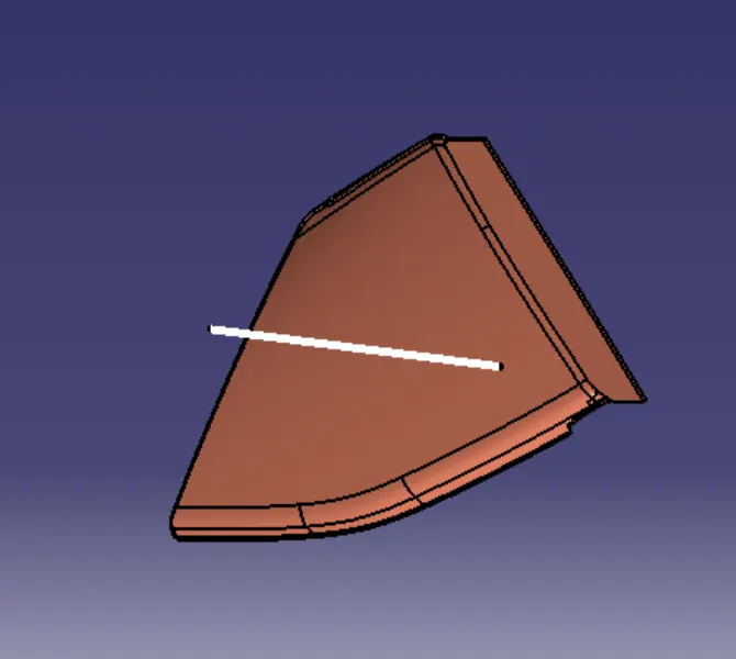
Engineering features
Flange
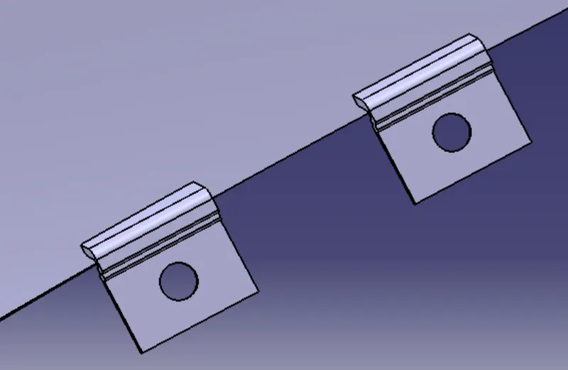
Flanges were created on the arm rest with the reference dimensions from the master sketch provided. The purpose of the flange was to provide slots for the heat stakes and locator which are required to assemble the two components together and constraint the motion between them.
Draft analysis
Class A
Final
Final assembly
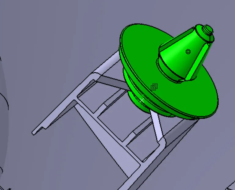
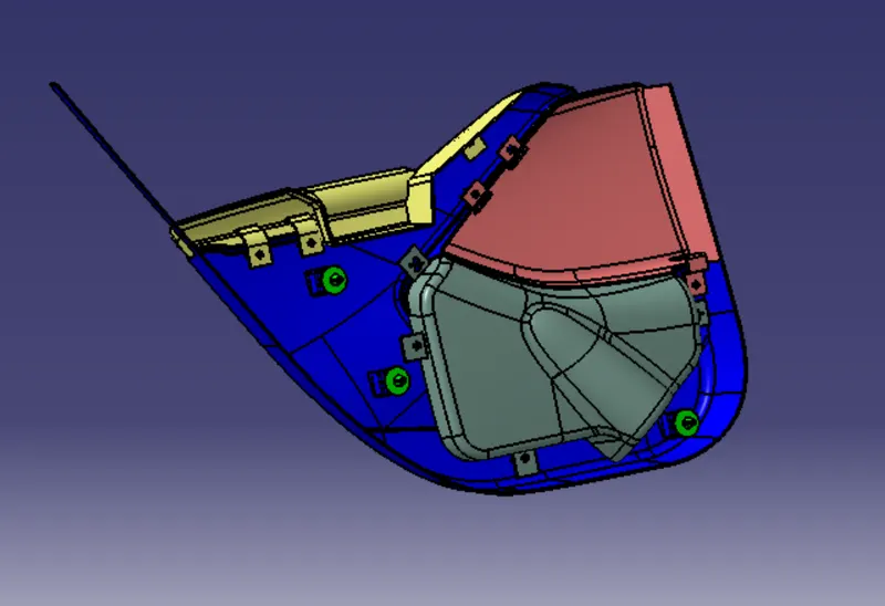
The final assembly of the door trim involved the insertion of the push clips into the respective dog house slots. Using the dog house central axis and the axis of the push pin coincident relation was given. After which, using contact constraint the push clips were made to sit in the dog house slot as required.
Final assembly
Conclusion,
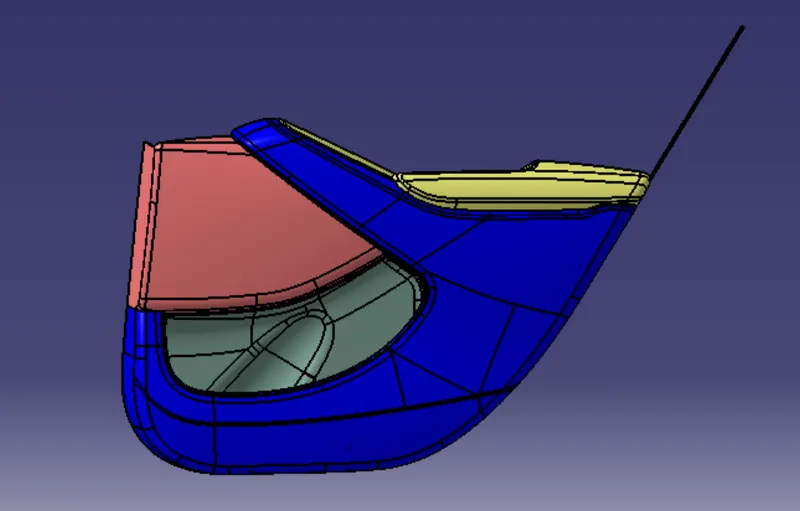
Thus the designing of side door panel is created and all components are assembled successfully.