Week 11 - Final project
Week 11 - Final project
AIM:- To design the car door inner panel with reference to given Class-A surface by using given mastersection, creating attachment features and performing draft analysis to check the manufacturing feasibility of the component by using software CATIA V5.
Objective:- The project deals with the explanation of method followed to develop door trim inner panel. In this with the given Class-A surface, Class-B surface and Class-C surface were created along with the tooling axis. Other attachment features were also created for assembly of the different components of door trim.
Methodology:-
The methodology of the project is explained here:
1. Class-A suface was extracted from the given surface.
2. Tooling Axis were created of the individual component.
3. Class-B and Class-C surface were created with the OEM guidelines.
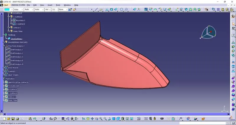
4. Formed Solid body from the closed surface.
5. Engineering features were created for attachment.
6. Draft analyses of each component was performed to check the manufacturing feasibility.
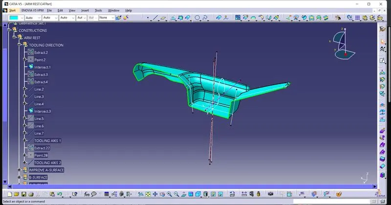
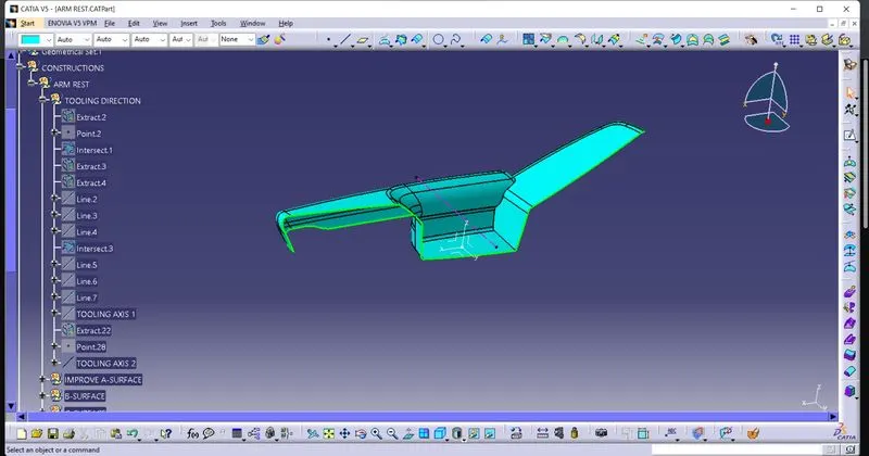
TOOLING AXIS:- The tooling axis is defined as the direction in which the mold or core and cavity opens is the tooling axis.
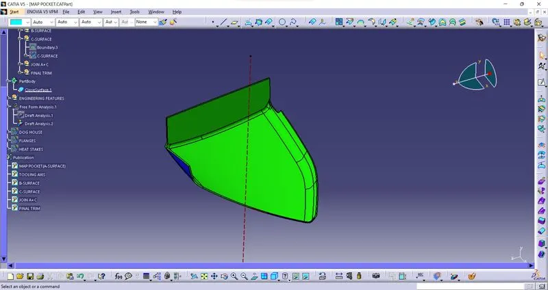
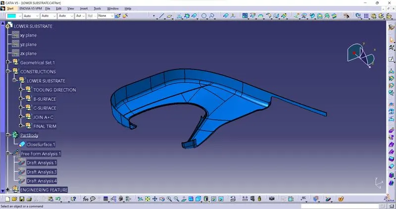
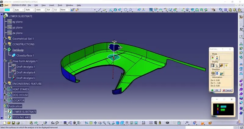
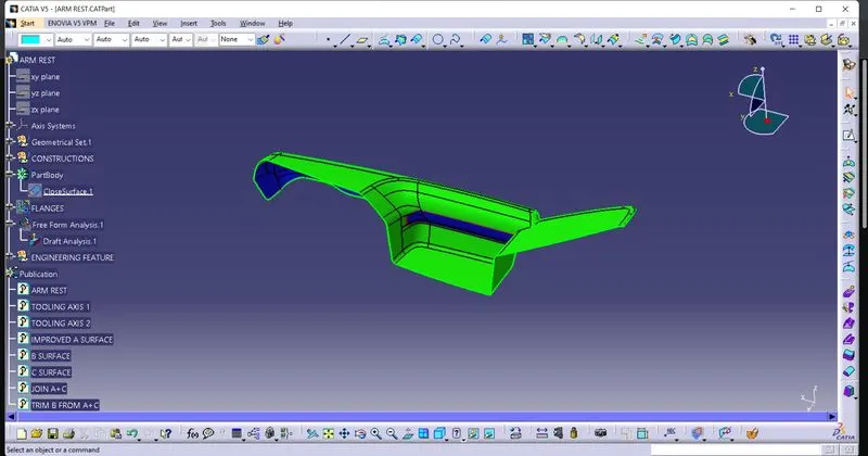
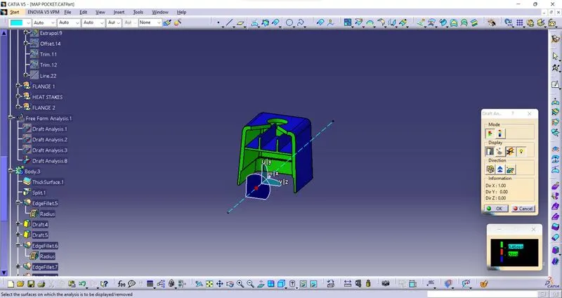
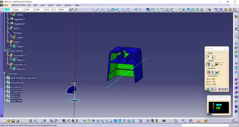
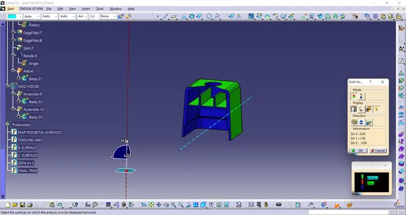
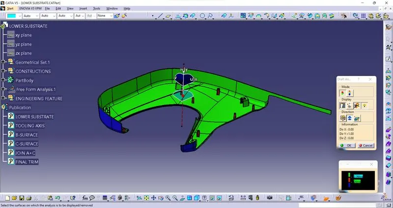
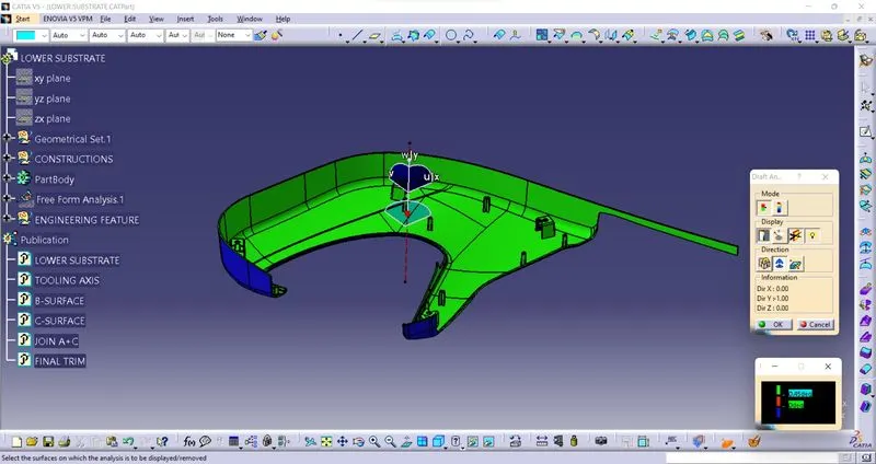
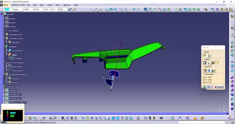
DRAFT ANALYSIS:- The Draft Analysis command enables you to detect if the part you drafted will be easily removed. This type of analysis is performed based on color ranges identifying zones on the analyzed element where the deviation from the draft direction at any point, corresponds to specified values.
CLASS A SURFACE:- A class A surface is any of a set of freeform surfaces of high efficiency and quality. Although, strictly, it is nothing more than saying the surfaces have curvature and tangency alignment – to ideal aesthetical reflection quality,
CLASS B SURFACE:- B surface is the thick wall of the component. The B surface is created by Class A surface reference of an offset of 2.5mm is used to create a Class B surface.
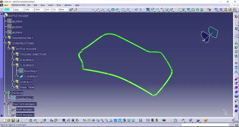
CLASS C SURFACE :- The C surface is the boundary of the component and it also joins the class A & B Surfaces.
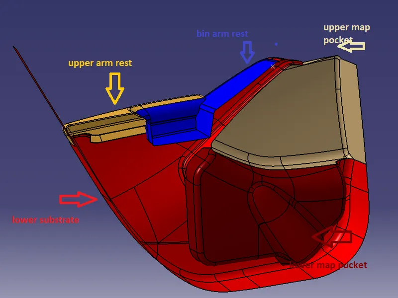
INTERIOR DOOR TRIM CONSISTS OF FOUR PARTS –
- Lower substrate
- Door armrest
- Upper map pocket
- Lower map pocket
1. MAP POCKET:-
CLASS A-SURFACE:-
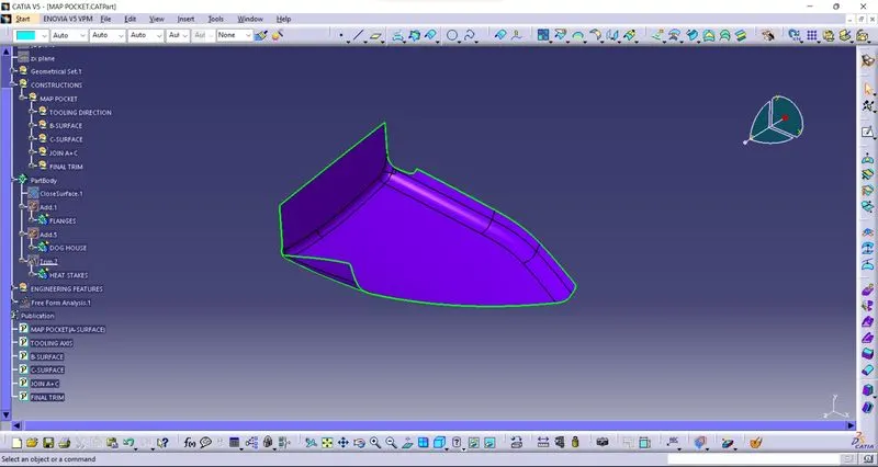
Analysis the A-surface and thens create the tooling axis.
TOOLING AXIS:-
- Since the component is visible from the Y direction, so that will be the tooling axis for the upper map pocket.
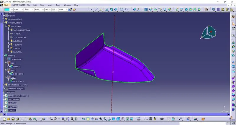
DRAFT ANALYSIS OF CLASS A-SURFACE:-
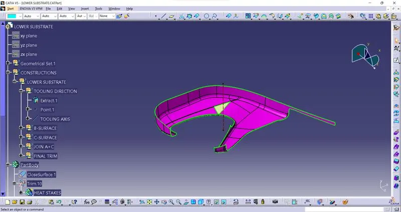
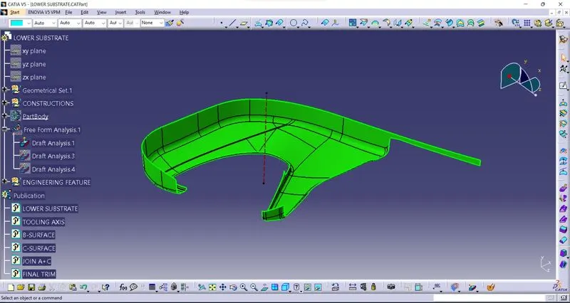
It is performed to check the manufacturing feasibilty of a component or part, in plastic manufacturing process we generally provide 3 degrees draft and 0.5 degree draft in critical conditions. To perform draft analysis first tooling axis was created by taking a point on surface and line was created in the direction in which part will form easily with provided draft.
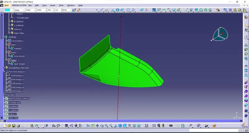
B-SURFACE:-
To create Class-B surface of map pocket, class-A surface was offset at a distance of 2.5mm and fill the gap with tlhe help of multisection tool.
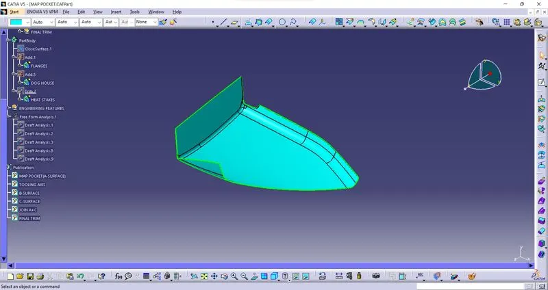
C-SURFACE:-
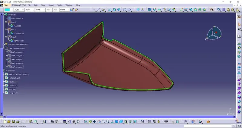
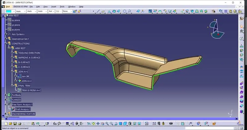
Class-C surface was swept from the boundary of the Class-A surface. Class-C surface was swept along with tooling direction.Then join the A+C surface and Trim the B-surface from join A+C.
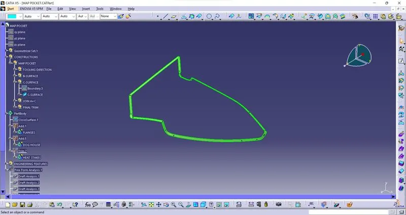
JOIN A+C SURFACE:-
FINAL TRIM:-
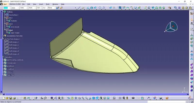
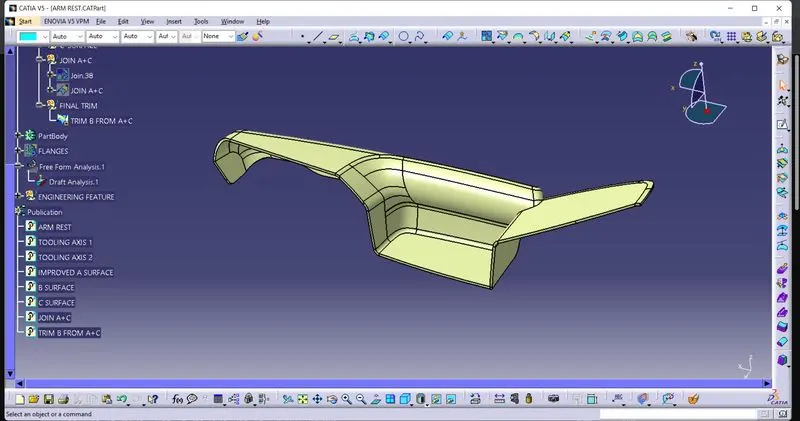
Trim the B-surface from join A+C surface to get the closed body.
SOLID BODY:-
DRAFT ANALYSIS ON SOLID BODY:-
GEOMETRICAL FEATURE:-
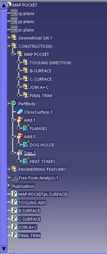
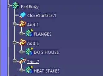
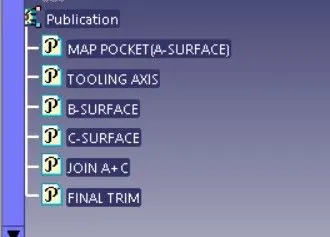
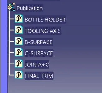
PUBLICATION:-
2.BOTTLER HOLDER:-
CLASS A-SURFACE:-
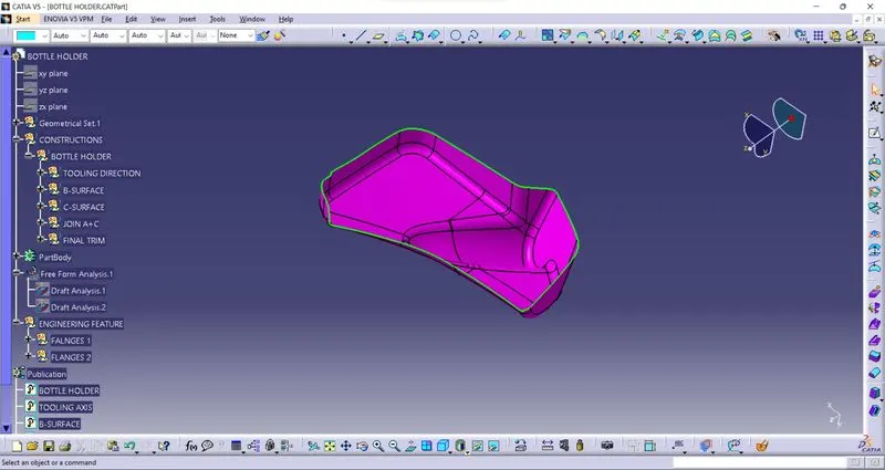
TOOLING AXIS:-
For tooling axis i have applied same approch which i applied for map pocket.
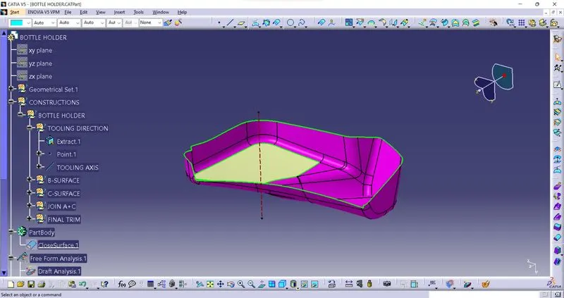
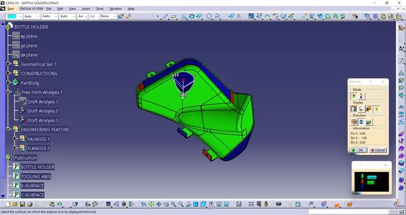
DRAFT ANALYSIS OF CLASS A-SURFACE:-
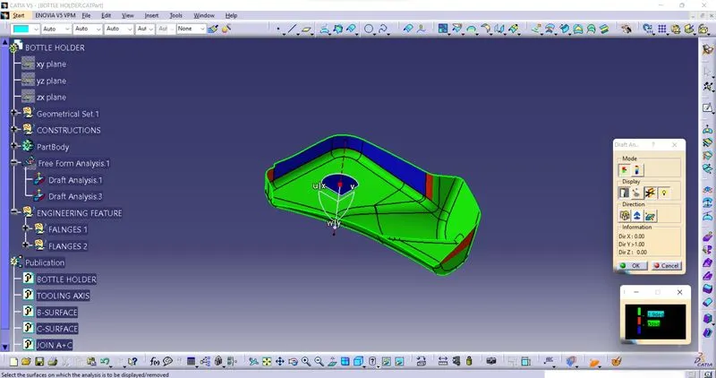
NOTE:- In this draft analysis and found the draft is not clear at some area of the A-surface and then i consult the instructer and i made the solid body with the same tooling axis direction(Y direction).
B-SURFACE:-
Just offset the A-surface 2.5mm.
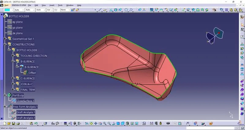
C-SURFACE:-
To create c-surface select the boundary and swept along with tooling direction.Then join the A+C surface and Trim the B-surface from join A+C.
JOIN A+C SURFACE:-
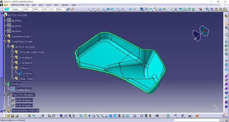
FINAL TRIM:-
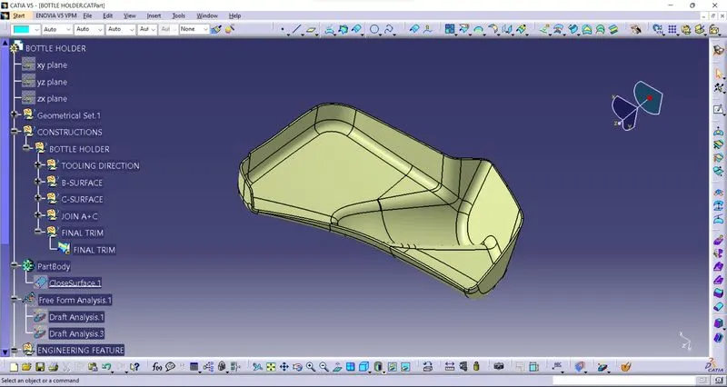
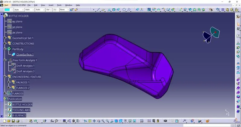
SOLID BODY:-
DRAFT ANALYSIS ON SOLID BODY:-
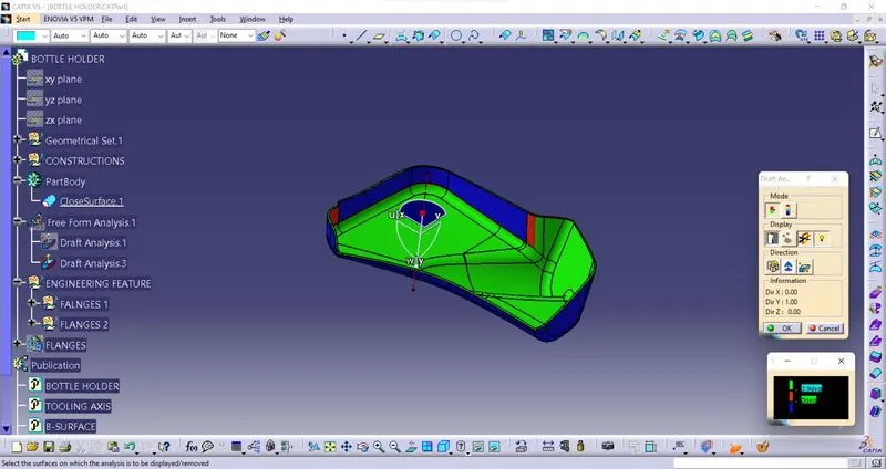
Note- solid body draft is not clear because A-surface draft was not clear.
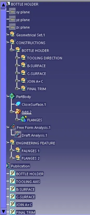
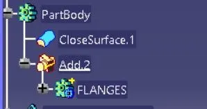
GEOMETRICAL FEATURE:-
PUBLICATION:-
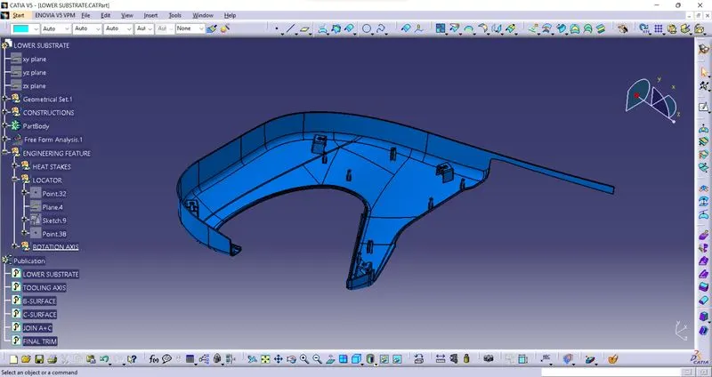
3.LOWER SUBSTRATE:-
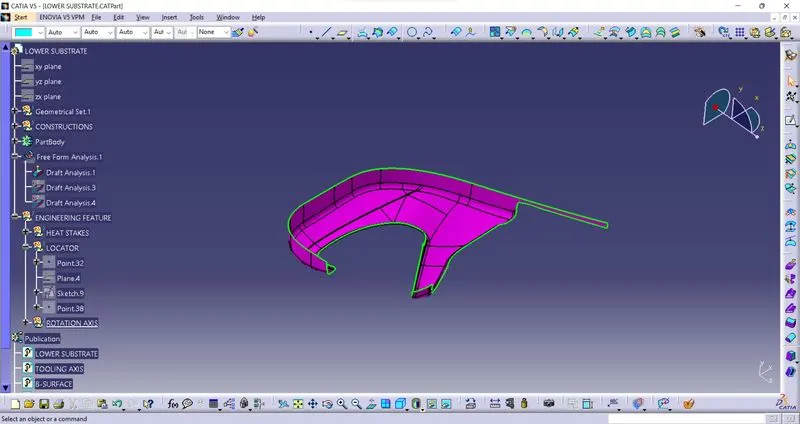
CLASS A-SURFACE:-
TOOLING AXIS:-
- Since the component is visible from the Y direction, so that will be the tooling axis for the upper map pocket.
DRAFT ANALYSIS OF CLASS A-SURFACE:-
B-SURFACE:-
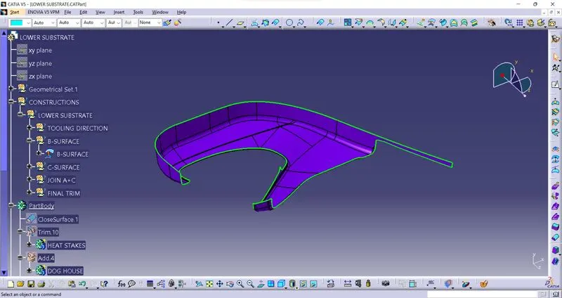
Just offset the A-surface 2.5mm.
C-SURFACE:-
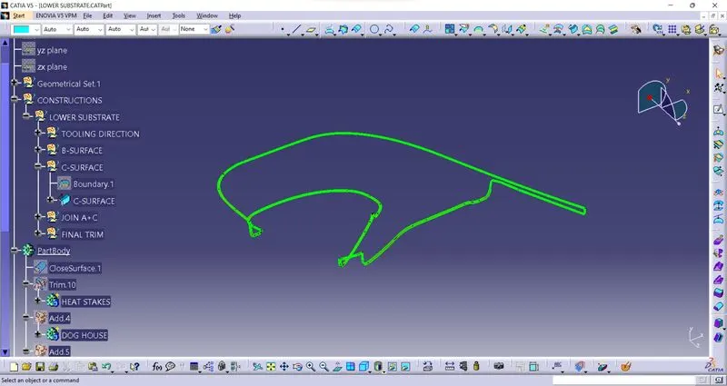
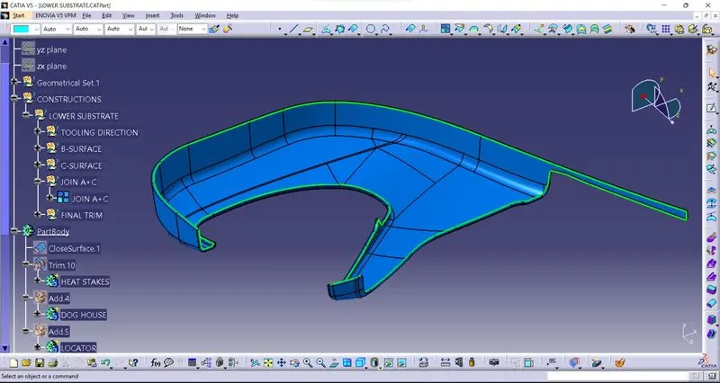
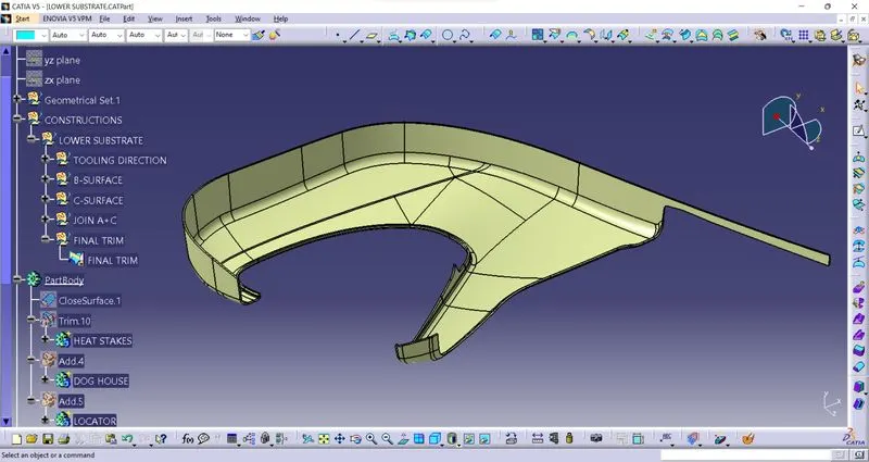
To create c-surface select the boundary and swept along with tooling direction.Then join the A+C surface and Trim the B-surface from join A+C.
JOIN A+C SURFACE:-
FINAL TRIM:-
SOLID BODY:-
DRAFT ANALYSIS ON SOLID BODY:-
GEOMETRICAL FEATURE:-
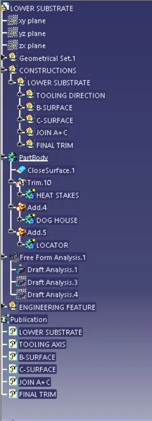
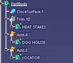
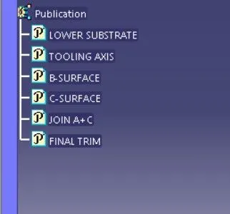
PUBLICATION:-
4.ARM REST:-
CLASS A-SURFACE:-
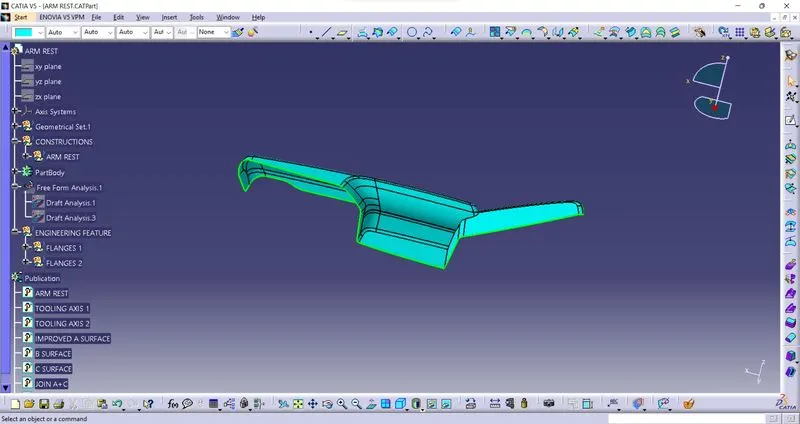
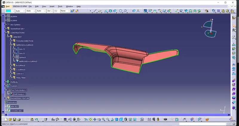
NOTE:- check the A-surface with boundary command i found some area are open then first i modified the A-surface and then create other body.
MODIFIED CALSS A-SURFACE:-
TOOLING AXIS:-
DRAFT ANALYSIS OF CLASS A-SURFACE:-
B-SURFACE:-
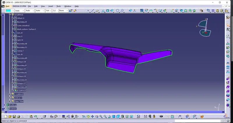
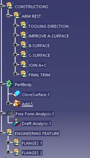
For B-surface i hace offset the A-surface and fill the gap area with the help of multisection,extrude,extrapolate and some other command with you can see in the tree structure which i provided along with B-surface, which is given below.
C-SURFACE:-
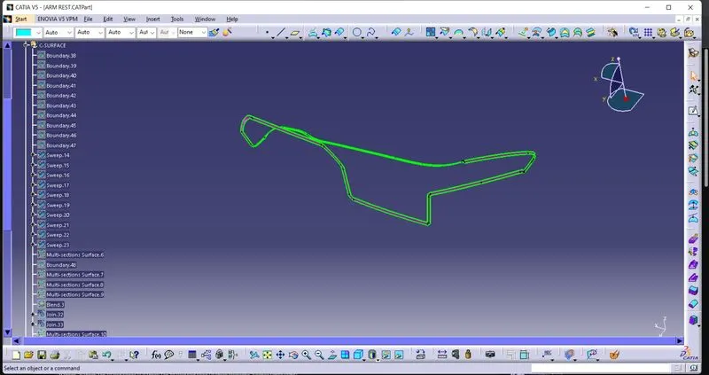
To create the C-surface first i have used swep command for some are 3 degree with draft and for some area reference surface with 90 degree.
and also blend and multisection command to create the proper c-surface and then join A+C surface and Trim B-surface form A+C.
JOIN A+C SURFACE:-
FINAL TRIM:-
SOLID BODY:-
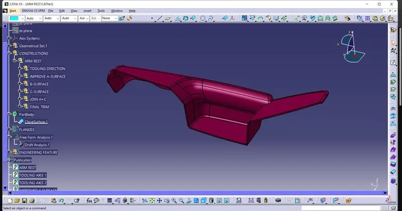
DRAFT ANALYSIS ON SOLID BODY:-
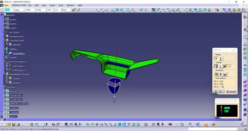
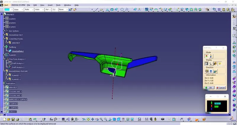
GEOMETRICAL FEATURE:-
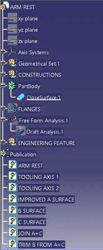
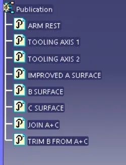
PUBLICATION:-
Attachment features:-
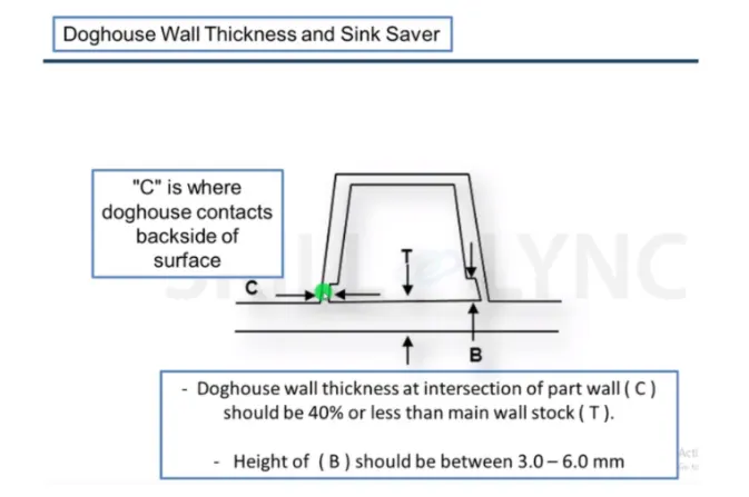
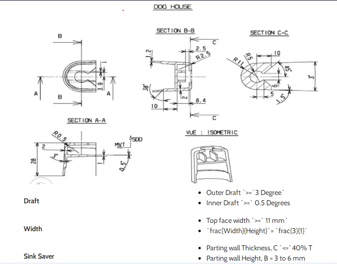
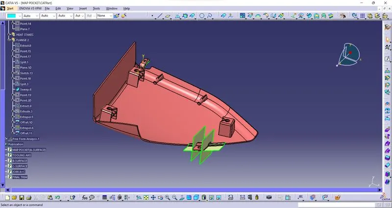
DOGHOUSE:- Doghouse is an engineering feature used in the plastic trim design which helps to remove sink marks formed on Class-A surface while creating attachment feature on Class-B surface. Doghouse is a supporting feature, other features like locators, heat stakes, pushpins are mounted on top of doghouse for fixing and assembly purpose. Doghouses are subjected to draft analysis to prevent breakage of the component during ejection from the mould.
Flanges:-
Flanges are the additional layer that is used as an attachment holder which gives strength to the component. It is generally used to connect the pipes, valves, etc. Flanged joints are made by bolting together two flanges with a gasket between them to provide a seal.
Push Pins:-
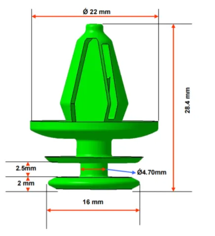
Push Pin or clip is used to hold the door onto the inner panel. The Pushpins are attached to the doghouses and the clips are made of plastic material that can be replaceable.
Heat Stakes:-
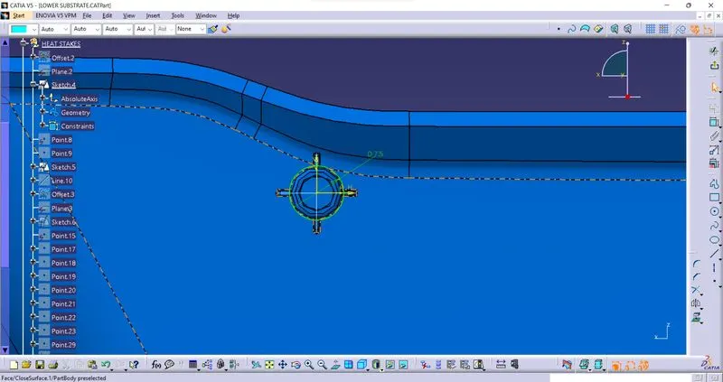
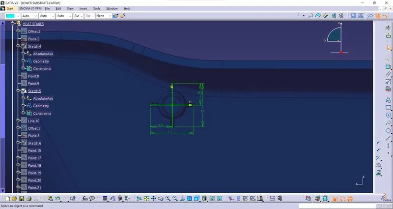
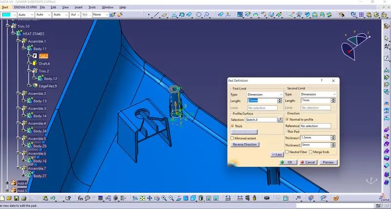
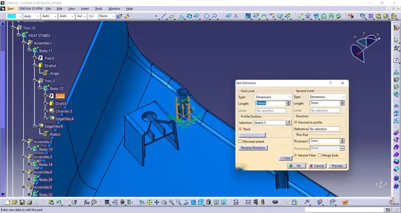
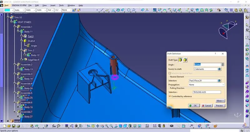
Heat Stakes is an assembly method that uses the controlled melting and reforming of the plastic stud or boss to capture or lock another plastic or metal component of an assembly in place.
The plastic stud protrudes through a hole in the component to be locked in place. The Heated thermal Tip contacts the top of the stud, which melts and fills the volume of the tip cavity to
produce a head, locking the component in place.
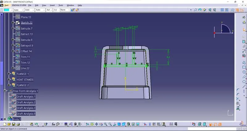
Ribs:- Ribs are the feature that provides stiffness to the parts and toughness without increasing the thickness of the part.
Locators:- Locators provide easy alignment to the parts which are mating with each other.
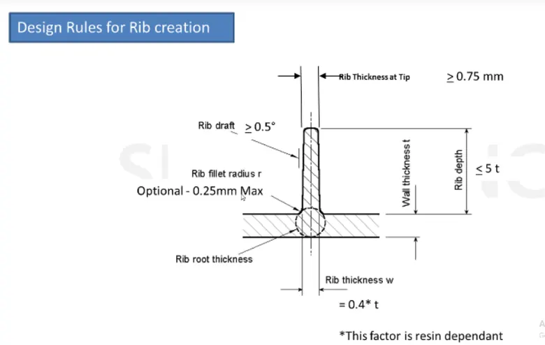
1. DOG HOUSE:-
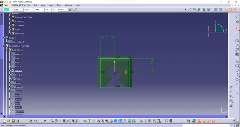
SKETCH:-
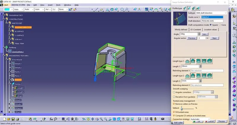
SWEEP:-
THICKNESS:-
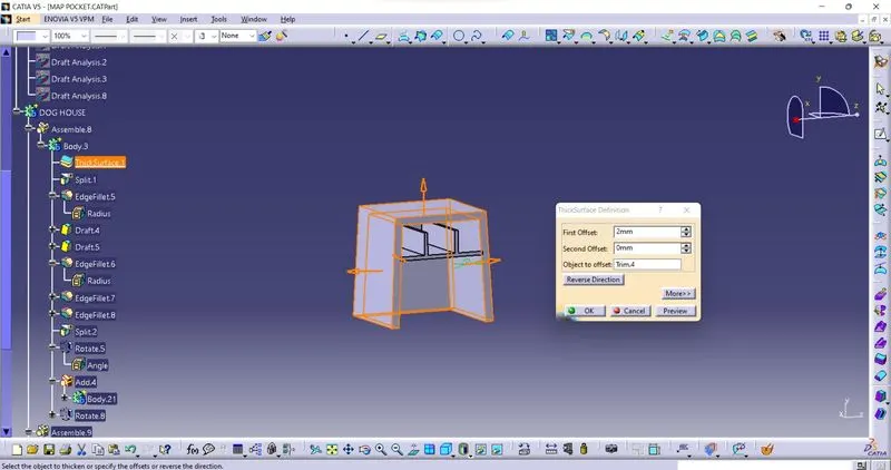
LOWER SECTION:-
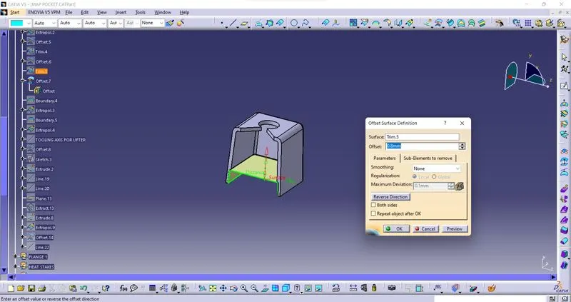
DRAFT:-
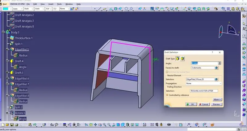
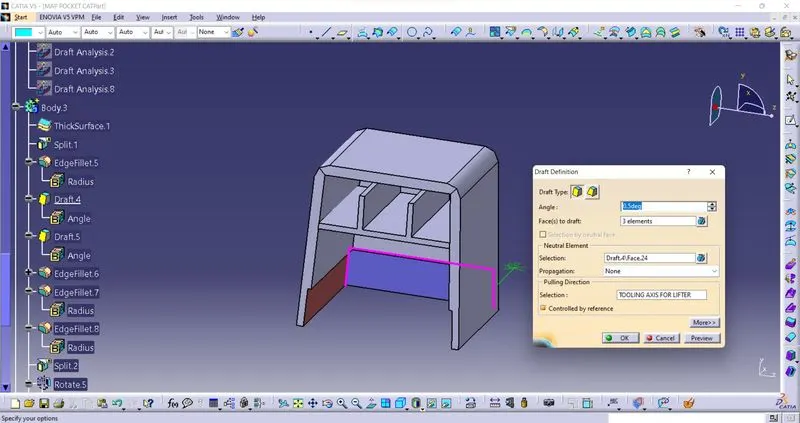
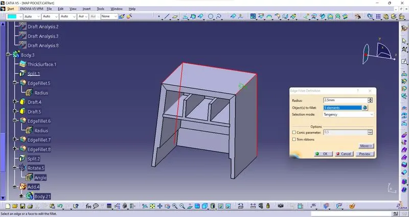
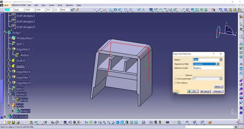
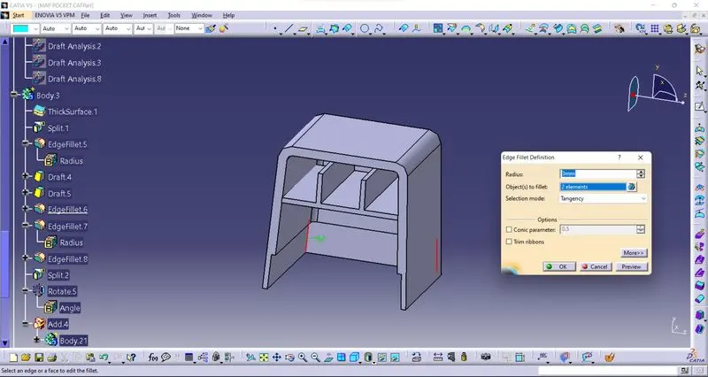
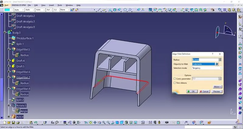
EDGES:-
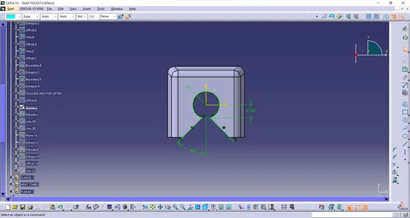
HOLE SKETCH FOR PUSS PIN:-
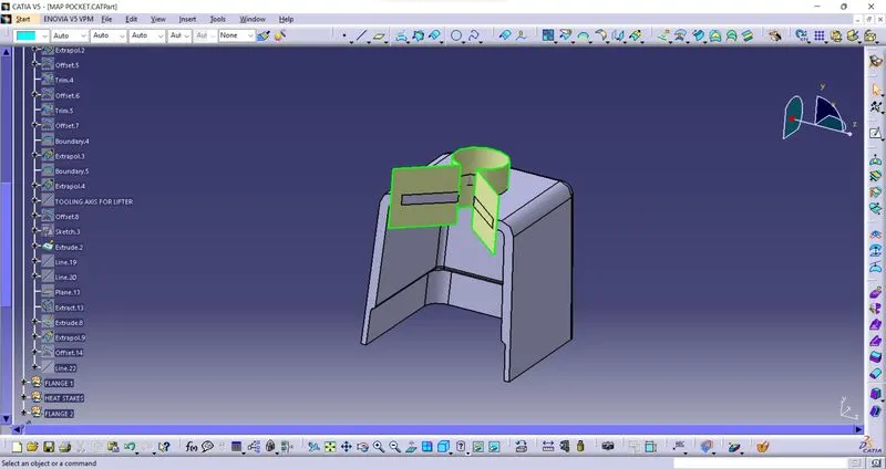
RIBS:-
DRAFT FOR RIBS:-
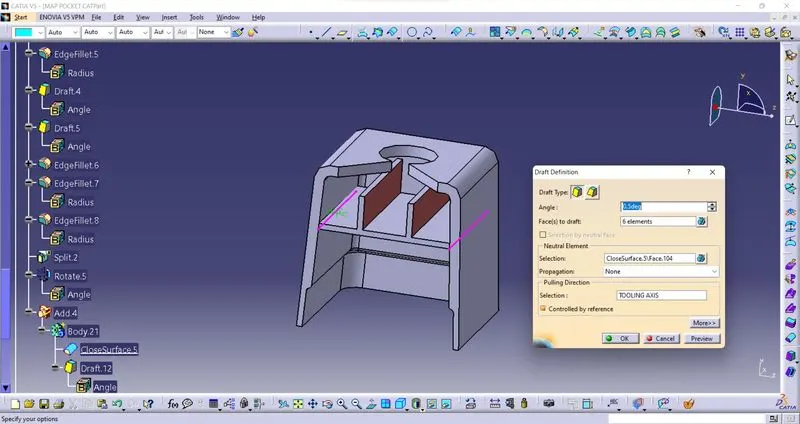
DRAFT ANALYSIS:-
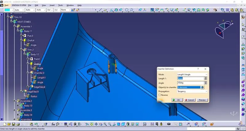
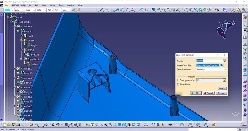
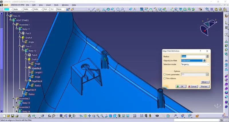
2. HEAT STAKES:-
SKETCH:-
PAD:-
DRAFT:-
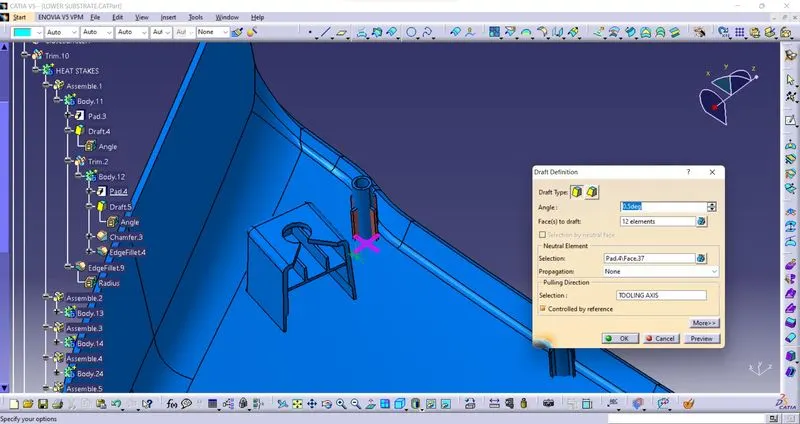
CHAMPHER AND EDGE FILLETS:-
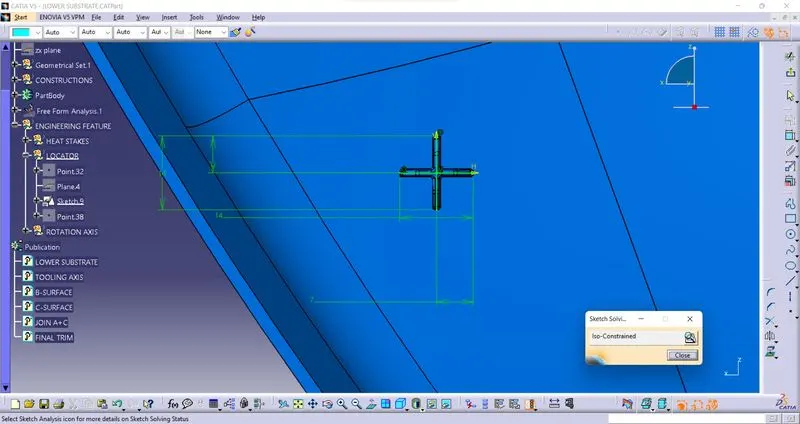
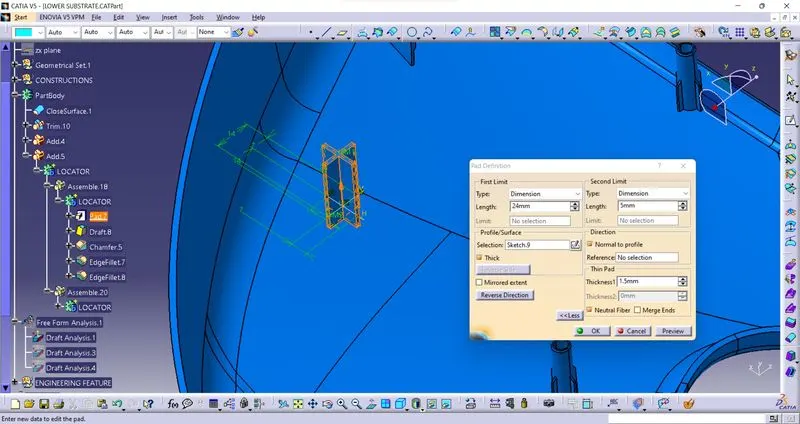
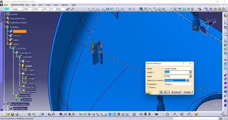
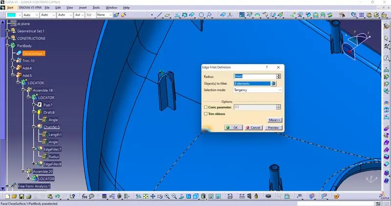
3.LOCATOR:-
SKETCH:-
PAD:-
DRAFT:-

CHAMPHER AND EDGE FILLETS:-
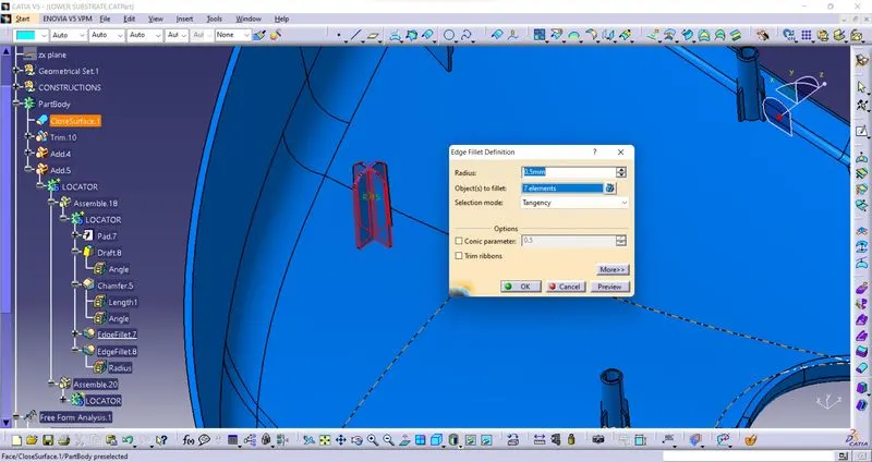
DOG HOUSE,HEAT STAKES AND LOCATOR AT SOME PART BODY WITH DRAFT ANALYSIS:-
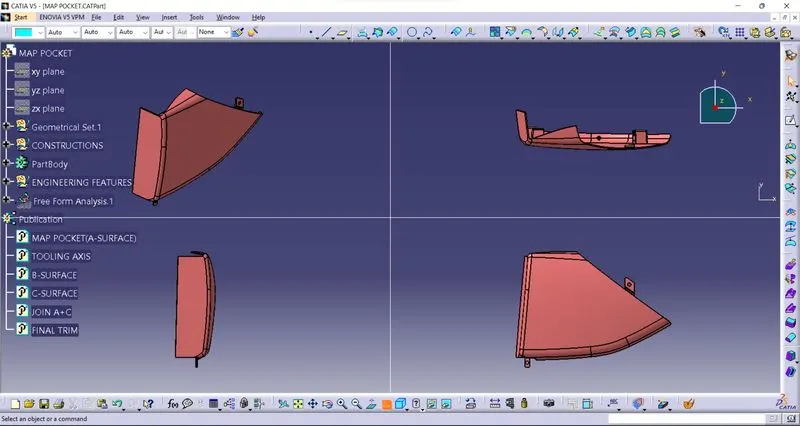
1. MAP POCKETS:-
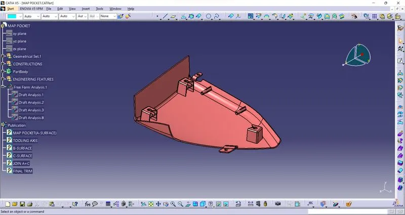
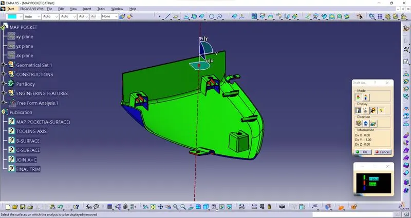
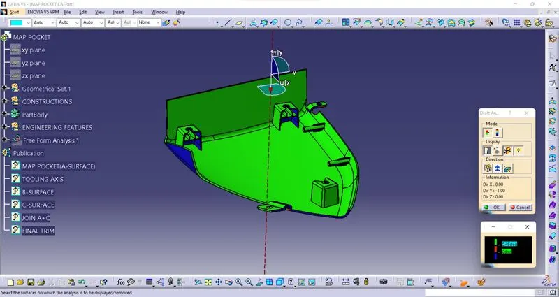
ALL IN ONE FRAME:-
2.LOWER SUBSTRACT:-
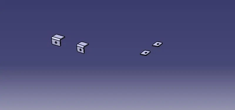
FLANGES:-
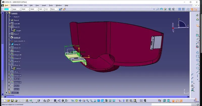
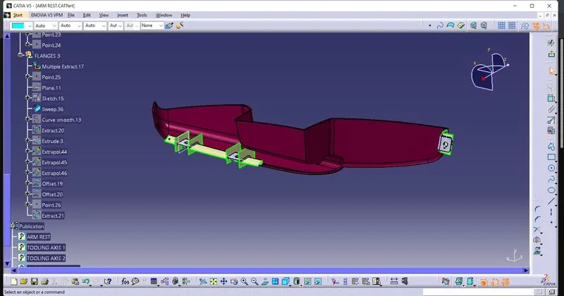
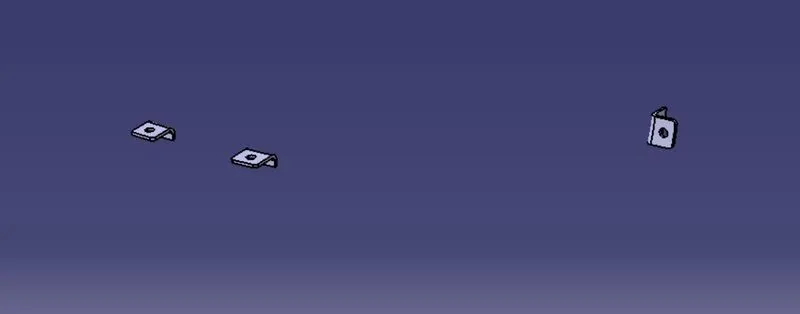
To create flanges first i have extracted the boundary where flanges to be bulit after that create a point on the extracted line and and take a plane and with help of master section and sweep the sketch along with the extracted line and gave the thickness 2.5mm which given in master section after that i took a line and extrude in needed direction and offset and after that i apply trim command of part body to create the final flanges and add with the main body.
FLANGES AT SOME PART BODY GIVEN BELOW:-
1.ARM REST:-
DRAFT:-
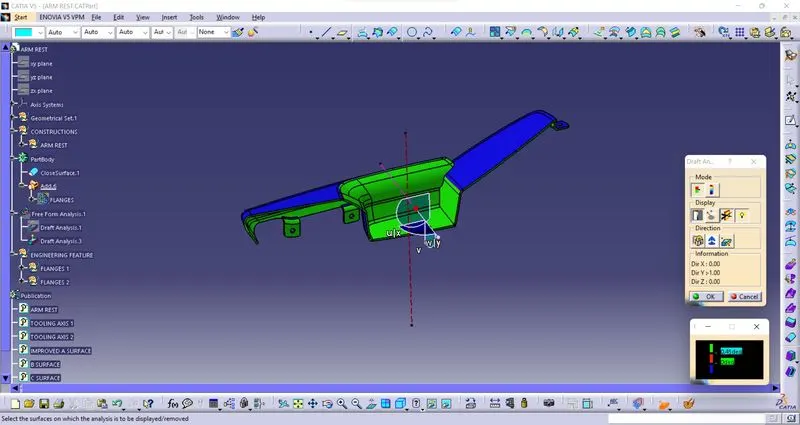
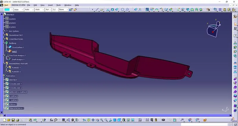
ALL IN ONE FRAME:-
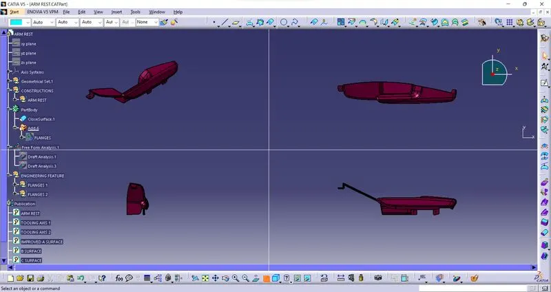
2.BOTTLE HOLDER:-
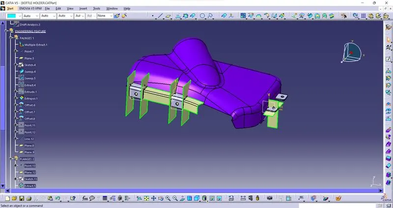
DRAFT:-
ALL IN ONE FRAME:-
3. MAP POCKET:-
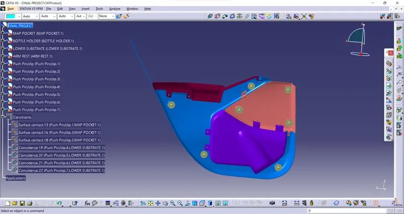
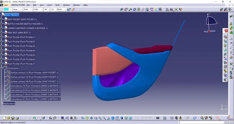
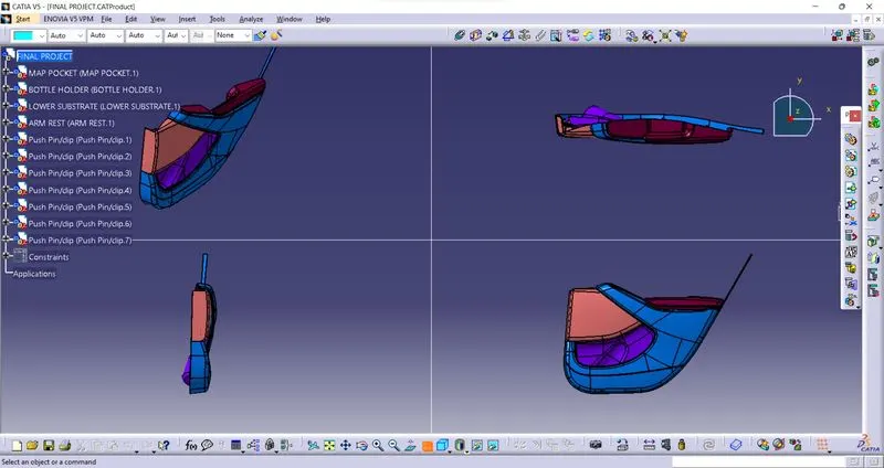
ASSEMBLY:-
First i have imported all part body and then imported the puss pin which is given and then attached the puss pin at all requried position with the the help of coincidenc and contact command which you can see in geometrical tree structure.
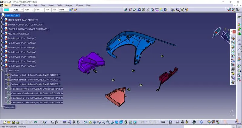
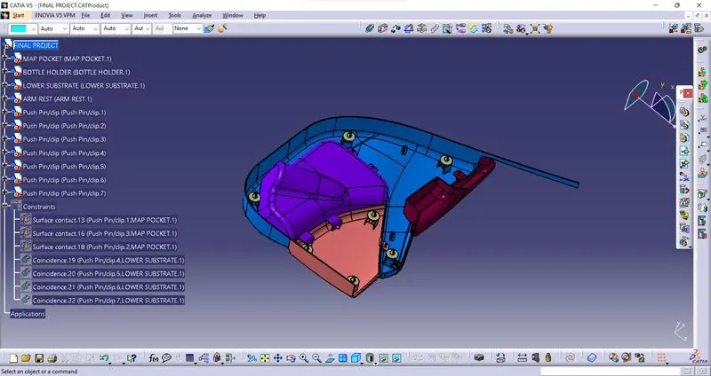
GEOMETRICAL TREE STRUCTURE:-
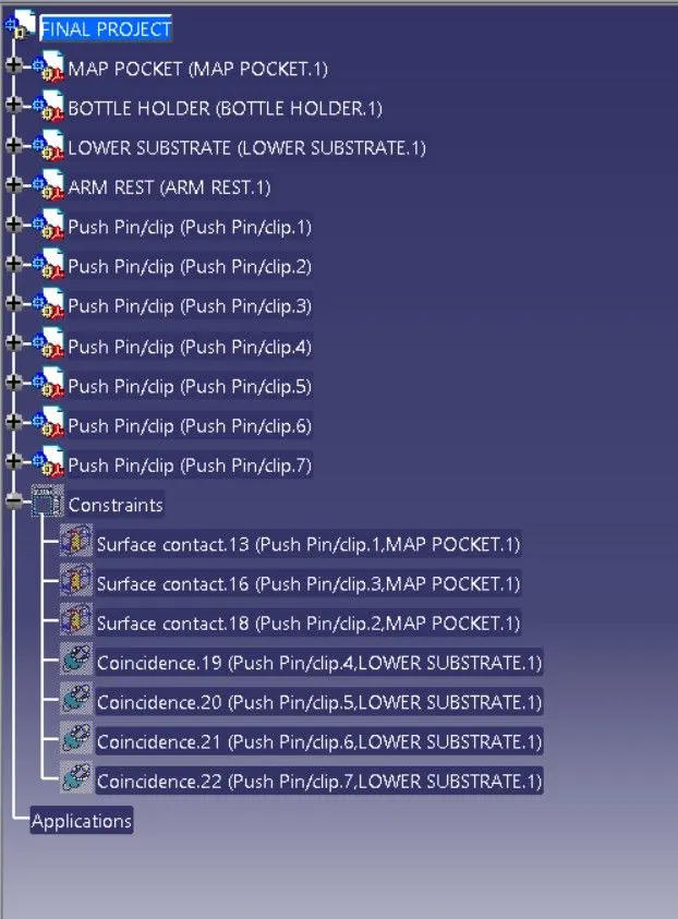
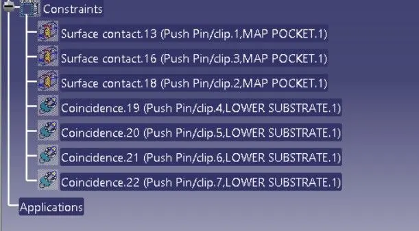
ISOMETRIC VIEW:-
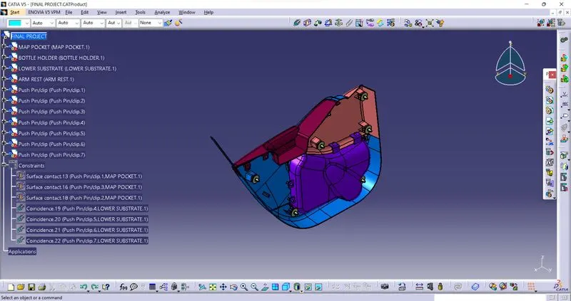
FRONT VIEW:-
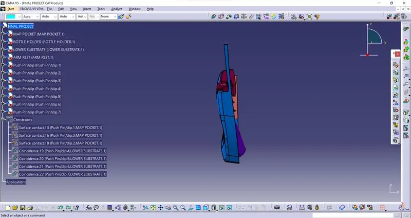
SIDE VIEW:-
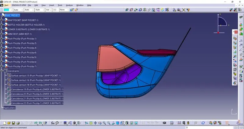
TOP VIEW:-
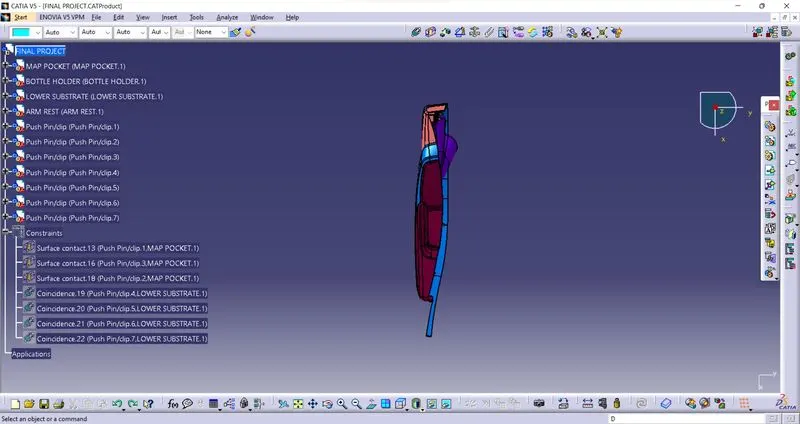
ALL VIEW IN ONE FRAME:-
SHADING :-