Week -2
DOORBELL USING SOLENOID
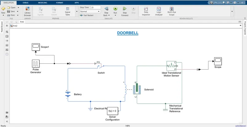
To make this Simulink model (Doorbell using solenoid) following blocks are used which is given below:
- PULSE GENERATOR- (to create square wave in regular interval)
- SCOPE 1- (to show the result of pulse generator in simulation time)
- BATTERY- (to external voltage source)
- ELECTRICAL REFERENCE- (to represent the electrical ground)
- SWITCH- (to control the input source pass through to the output)
- SOLVER CONFIGURATION- (to start simulation)
- SOLENOID- (to attract magnetic material)
- IDEAL TRANSLATIONAL MOTION SENSOR- (to converts an across variable measured between two mechanical translational nodes)
- MECHANICAL TRANSLATIONAL REFERENCE- (to represent a reference point for all mechanical translational ports)
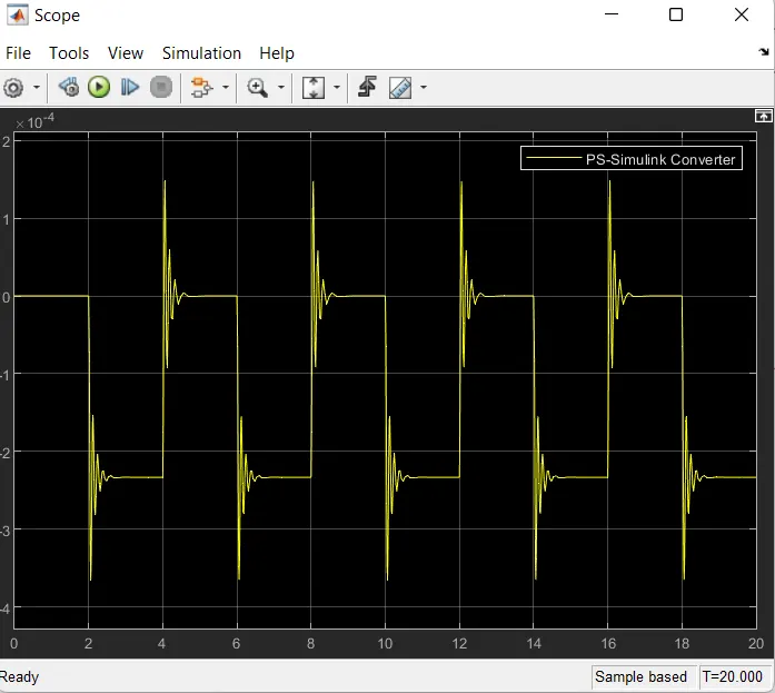
- SCOPE- (to show the result of doorbell which is ringing after 2sec interval)
EXPLANATION-
When current passes through the wire the magnetic field is generated around the solenoid block because solenoid is electromagnetic so it attracts the magnetic materials due to this doorbell is rang. In the above diagram when the switch will be on the current will pass through the circuit and create a electromagnet due to this pulling the plunger towards the metal surface and produces the sounds of ring.
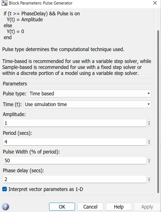
In the above model I have used a pulse generator block as an input to produces pulse at every two seconds. You can see the result in diagram which is given below and this process running for twenty seconds.
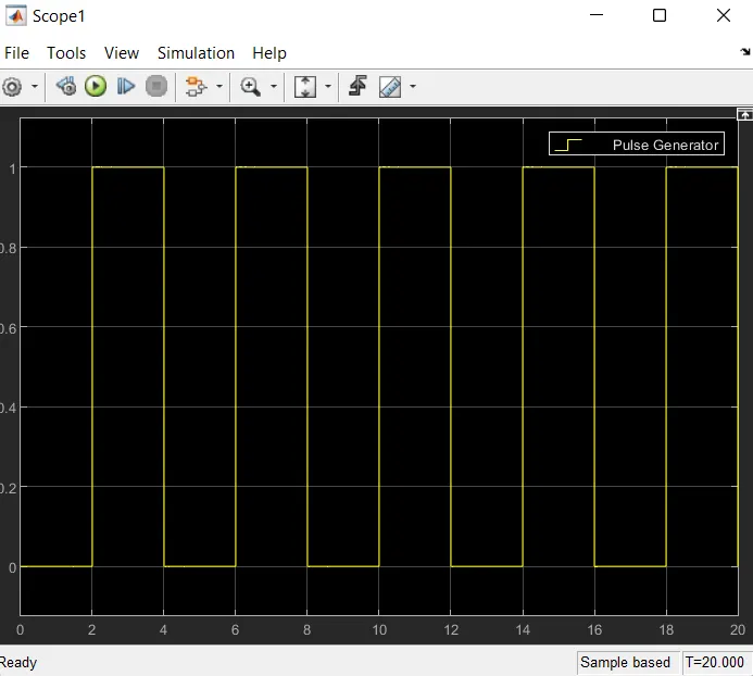
According to the question circuit should be closed only in two seconds that’s why switch block has been used circuit will close when threshold value of pulse generator will more than threshold value of switch block and for observing the plunger movement we use the ideal translational motion sensor you can see the result in diagram which is given below.
FAN CONTROL BY THERMISTOR
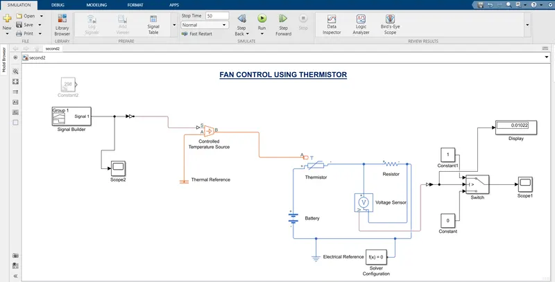
To make this model (fan control by thermistor) following blocks are used which is given below-
- SIGNAL BUILDER- (to provide signal at given interval)
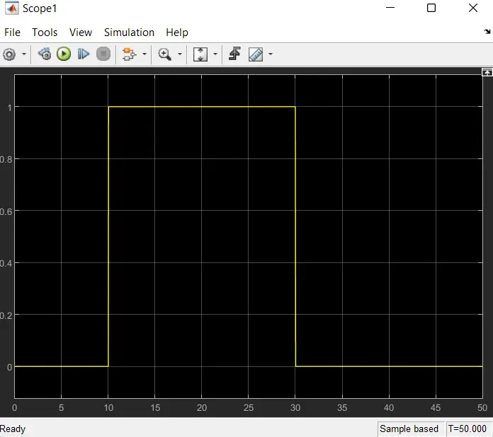
- SCOPE 2- (to see the result)
- CONTROLLED TEMPERATURE SOURCE- (an ideal source of thermal energy use to maintain temperature differences across all signals)
- THERMAL REFERENCE- (to represent a thermal reference point)
- THERMISTOR- (to measure temperature)
- BATTERY- (to supply voltage in circuit)
- VOLTAGE SENSOR- (a device that convert voltage measured any electrical connection into a physical signal proportion to the voltage)
- SWITCH- (to control the input voltage passes through to the output)
- CONSTANT 1
- CONSTANT 2
- SCOPE 1- (to show the graphical result)
- DISPLAY- (to show the digital result)
EXPLATION-
Thermistor is measuring device to measure the temperature it related to resistance and temperature so the resistance of thermistor increase or decrease with respect to temperature examples which are given below-
0 to 10 seconds 20degree Celsius
10 to 30 seconds 27degree Celsius
30 to 50 seconds 30degree Celsius
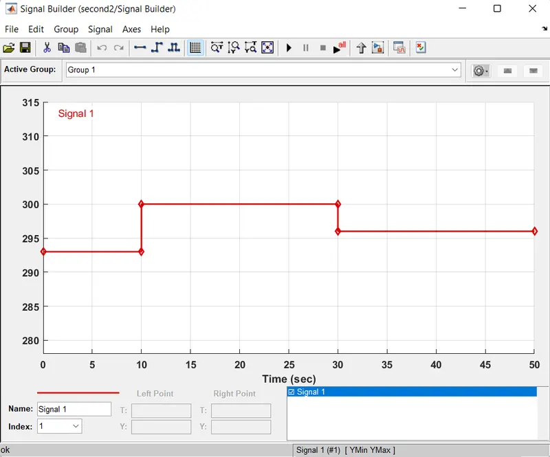
SIGNAL BUILDER INPUT
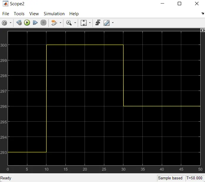
According to the question fan should be on when temperature sensed greater than 25degree Celsius. So that’s way I have used voltmeter block to find the voltage of circuit at different temperature and a switch block threshold value of the switch is 0.01107 at 25degree Celsius and it change at different temperature. The switch will be on when temperature is less than 25degree Celsius and vis-varsha. I can see the result in graph which is given below.