Design and development of car interior door trim panel
DESIGN OF VEHCILE DOOR TRIM PANEL USING MASTERSECTION
AIM : Design and development of car door trim panel using CATIA V5 tool with B-side features for alignment as per OEMs standards.
CONCEPT :Using Input class A as given development of Modified class A ,class B & class C are done.Using mastersection the thickness of the individual components and flanges are done.
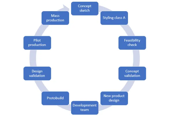
OVERVIEW : In this present article the complete automotive product life cycle and how a new product design is done will be explained.Coming to real time OEMs and tier 1 companies the design is firstly drawn as concept sketch and developed through styling class A team then comes to feasibility check moves to concept validation then to new product design.This report is detailed about car interior door with separate parts and manufacturing considerations in injection moulding is explained .
Master section : Master sections are the guides for design requirements which decide the component packaging after technical (Styling, Concept or Class-A) surfaces.
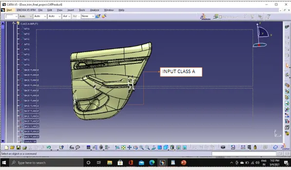
Class A - surface : Class A surfacing is done using computer-aided industrial design applications. Class A surface modellers are also called "digital sculptors" in the industry. Industrial designers develop their design styling through the A-Surface, the physical surface the end user can feel, touch, see.
Feasibility check : A feasibility study is an assessment of the practicality of a proposed project or system. A feasibility study aims to objectively and rationally uncover the strengths and weaknesses of an existing business or proposed venture, opportunities and threats present in the natural environment.
Concept validation :Concept validation allows you to build a detailed understanding of how your current and target customers feel about the core aspects of your offering before it’s launched in-market.
NPD (NEW PRODUCT DESIGN) :
Automotive product design and development. When it comes to product design and development it integrates quality prior to onset of the manufacturing phase, meets delivery & cost targets, truly recognizes and focuses on the most critical user inputs, Be optimized to consider the most efficient, effective automotive manufacturing solutions.
ATTACHMENTS : 1.Ribs
2.Doughouse
3.Heat stakes
4.Flanges
A car door is a type of door, typically hinged, but sometimes attached by other mechanisms such as tracks, in front of an opening which is used for entering and exiting a vehicle. A vehicle door can be opened to provide access to the opening, or closed to secure it. These doors can be opened manually, or powered electronically. Powered doors are usually found on minivans, high-end cars, or modified cars.
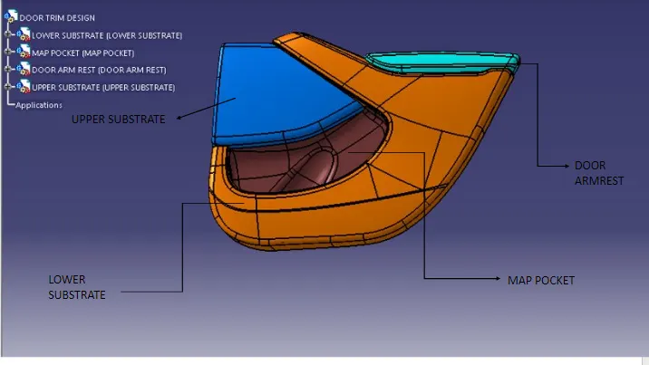
Interior door design consists of 4 components they are
- Upper substrate
- Lower substrate
- Map pocket
- Door armrest
In this model we are going to design a lower substrate,upper substrate,map pocket and door armrest with b-side features like doghouse,heat-stakes,flanges,ribs and draft analysis for following components.
Detailed design :
This may consist of procurement of materials as well. This phase further elaborates each aspect of the project/product by complete description through solid modeling, drawings as well as specifications.
Computer-aided design (CAD) programs have made the detailed design phase more efficient. For example, a CAD program can provide optimization to reduce volume without hindering a part's quality. It can also calculate stress and displacement using the finite element method to determine stresses throughout the part.
HERE,creation of class B & class C surfaces using Input class A are done and tooling axis,draft analysis are done here design engineer role is more prominent.
TOOLING AXIS FOR INDIVIDUAL COMPONENTS :
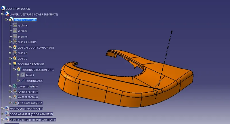
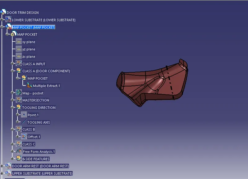
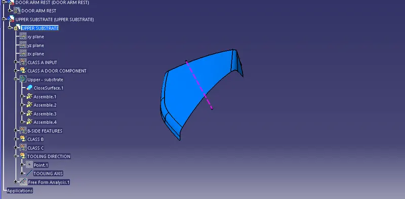
The Tooling Direction is basically the direction that the mold pulls apart. The mold is built in two separate pieces, basically. You have a Cavity side and you have the Core side. The Core pulls apart from the Cavity and that's the Dieline or the Tooling Direction.
- Tooling axis for Lower substrate
- Tooling axis for Map pocket
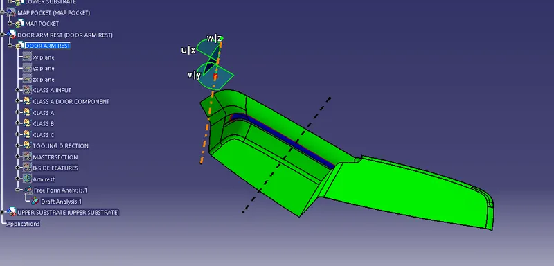
- Tooling axis Door armrest
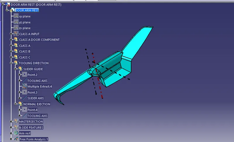
Here,In door arm rest there are two individual components and there are two tooling axis for door armrest slider axis and normal ejection i.e lifters
- Tooling axis for Upper substrate
DRAFT ANALYSIS FOR INDIVIDUAL COMPONENTS :
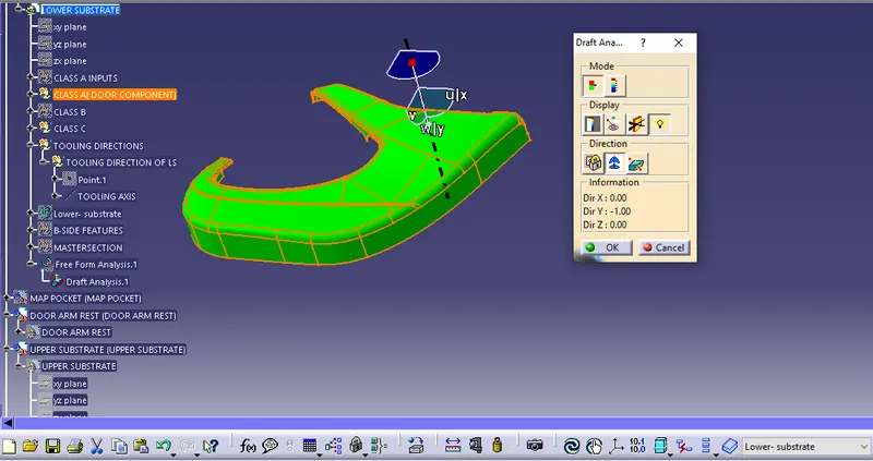
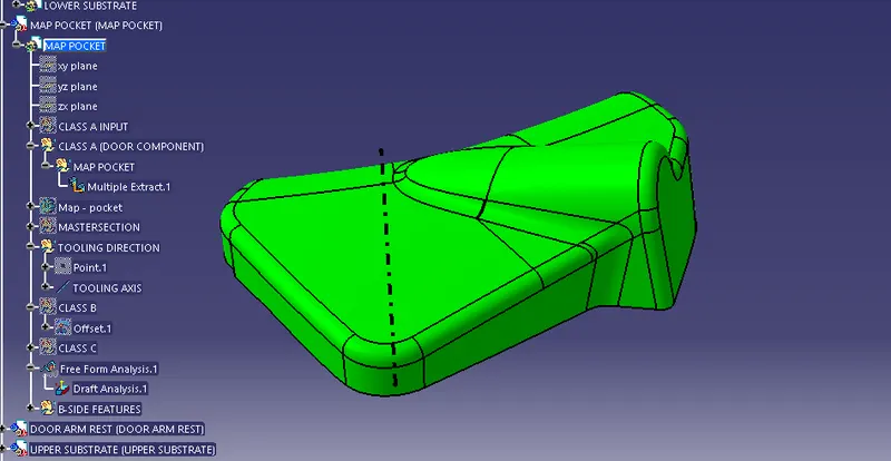
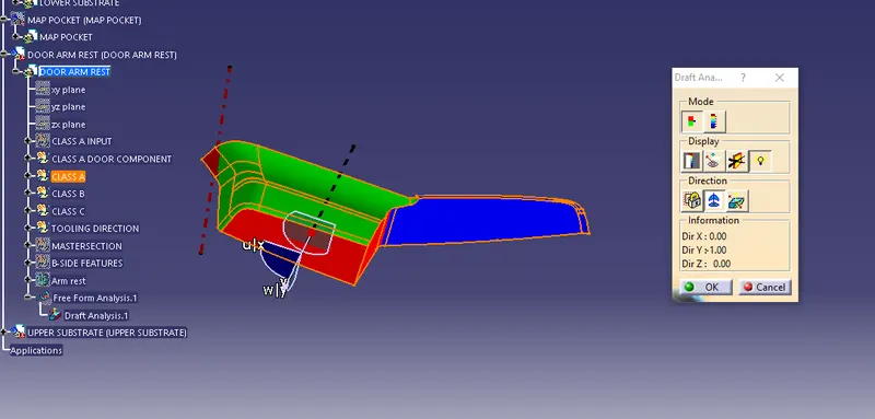
The Draft Analysis command enables you to detect if the part you drafted will be easily removed. This type of analysis is performed based on color ranges identifying zones on the analyzed element where the deviation from the draft direction at any point, corresponds to specified values.
- Draft analysis for lower substrate
- Draft analysis for Map pocket
- Draft analysis for Door armrest
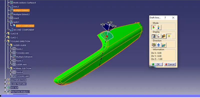
Here for perfect ejection of part we use slider axis
Creating Class B surface with reference of Class A surface :
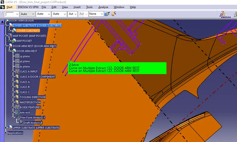
Using Master section of the input Class A thickness Between class A and mastersection is 2.5mm therefore,the surface is offset to 2.5mm.
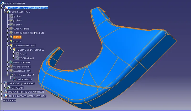
After creating tooling axis and draft analysis the next step is to create class B surface .A Class B surface is something that is not always visible i.e. the underside of a fascia that you would have to bend down to see. A Class C surface is the backside of a part of a surface that is permanently covered by another part. BIW is stuff like the body side etc.
- Class B surface of lower substrate
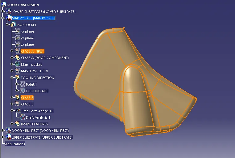
- Class B surface of Map pocket
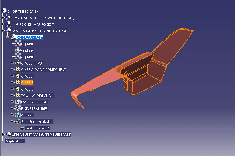
- Class B surface of Door armrest
- Class B surface of Upper substrate
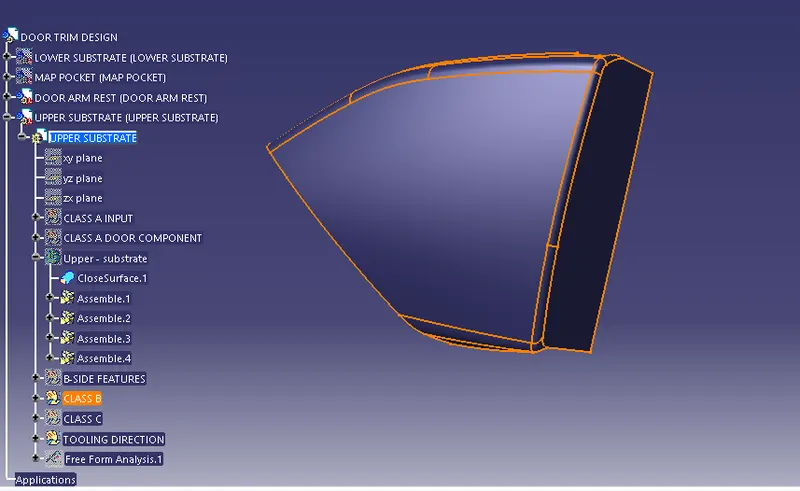
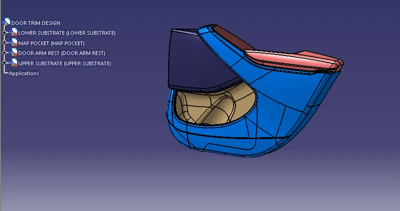
Complete Class B surface of door trim panel .
CREATION OF CLASS C SURFACE :
After completion of B surface.Now,its turn to create C surface .
In creating the class C surface there are three steps to follow for desired output.
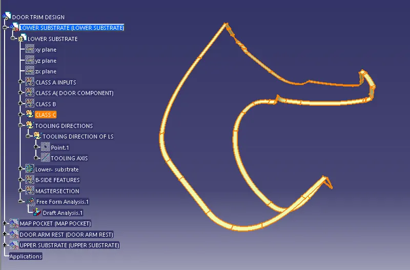
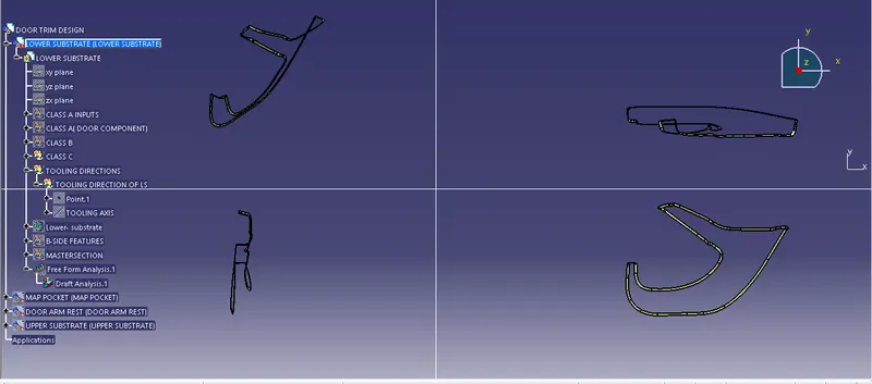
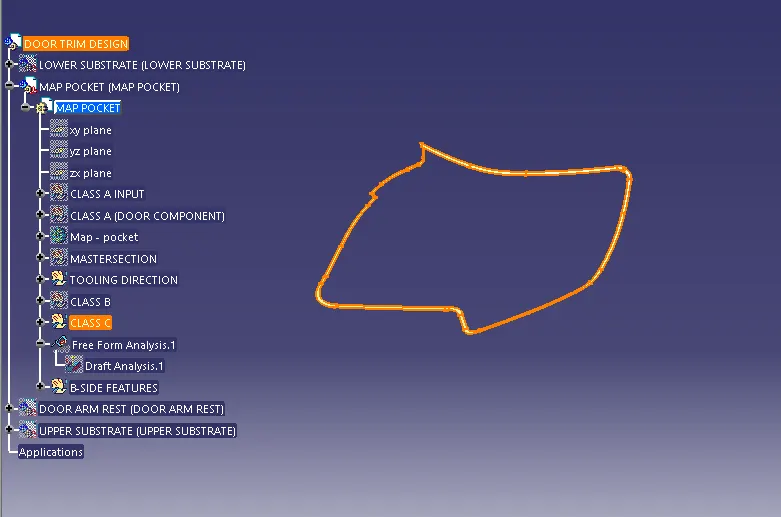
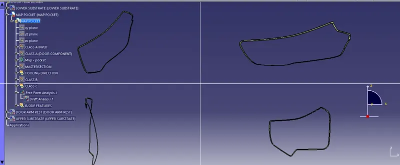
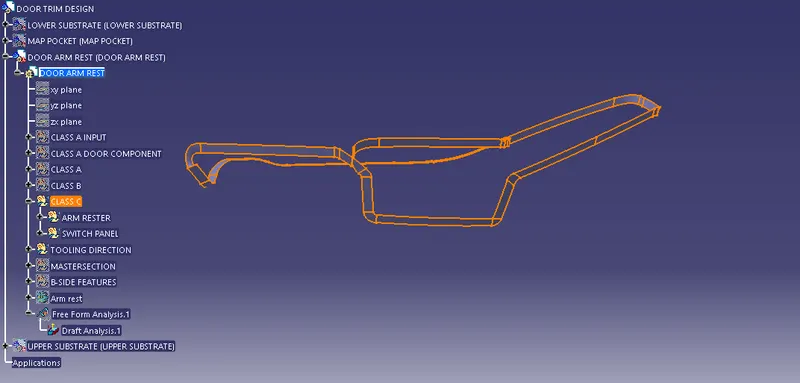
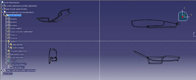
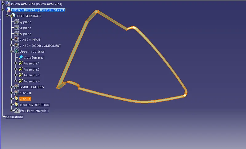
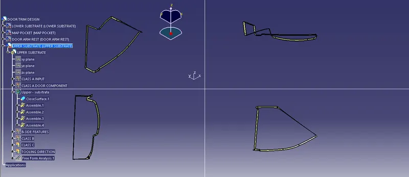
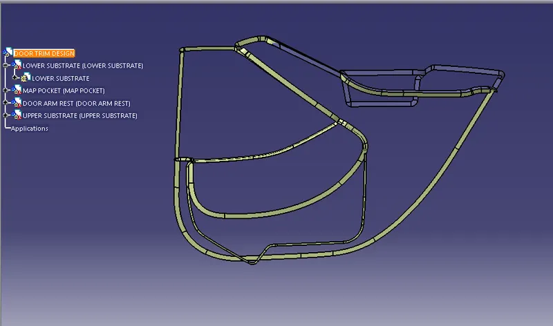
- Create the " C "surface using the boundary of class A surface.(Using sweep tool with draft direction of 1.5 Degree minimum value here we use 3 degree for easy ejection )
- Join Class A and Class C surface .
- Then,finally trim with the Class B surface with output join of A & C surface to get a closed body.
Class C surface of lower substrate :
Class C surface of map pocket :
Class C surface of Doorarm rest :
Class C surface of Upper substrate :
COMPLETE C SURFACE :
JOIN OF CLASS A & CLASS C AND TRIM WITH CLASS B TO GET CLOSED PROFILE :
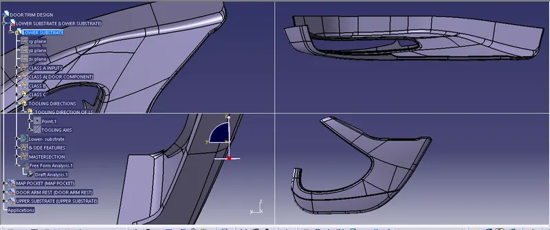
Once after Creating the Class B and Class C,First Join the Class A and Class C Surface together with a Connexity of Surface less than 0.003mm and The Surfaces are Merged.Merged Surfaces are than to be trimmed with Class b Surfaces to get a Closed surface.
- Lower substrate after joining A & C class Trimming With B class final output is below .
- Map pocket after joining A & C class Trimming With B class final output is below .
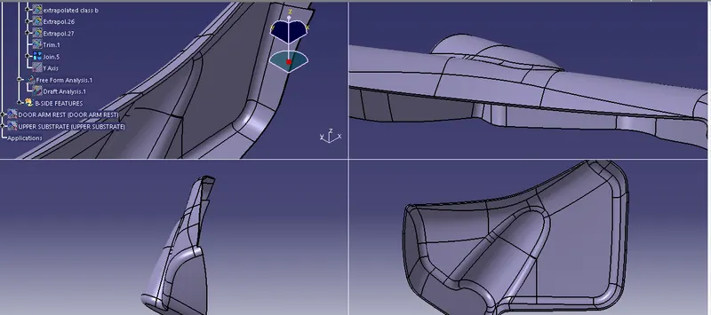
- Door arm rest after joining A & C class Triming With B class final ouput is below .

- Upper substrate after joining A & C class Trimming With B class final output is below .
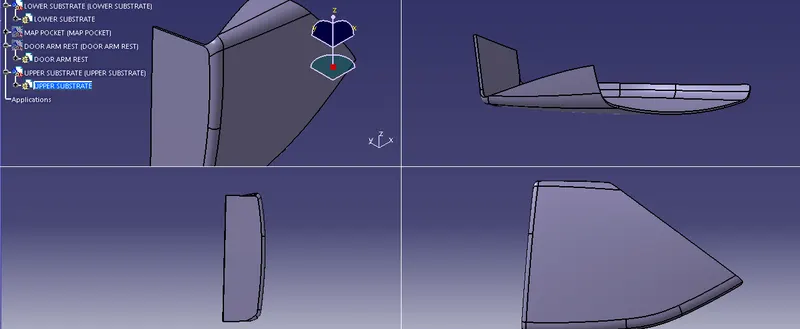
CLOSED BODY OF DOOR TRIM PANEL :
After creating join of A & C class trim with B class we get closed profile now switch to Mechanical design
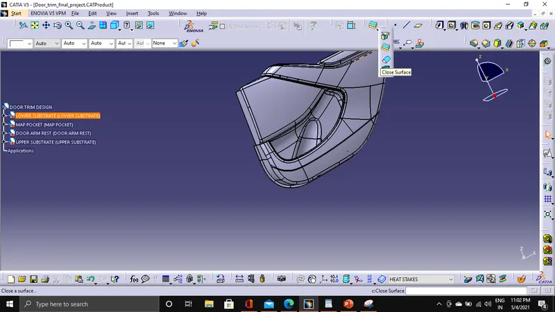
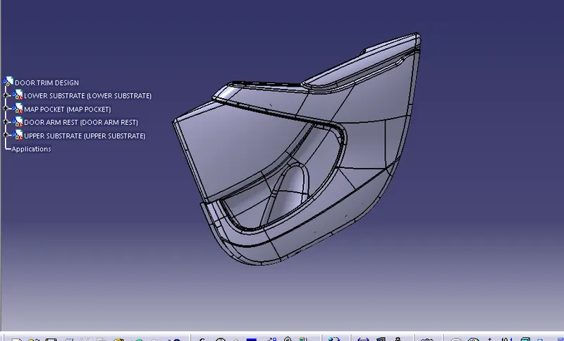
CREATION OF B SIDE FEATURES :
Considerations :
- Thickness
- Height
- Location
- Quantity
- Manufacturability
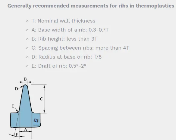
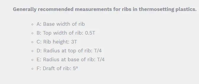
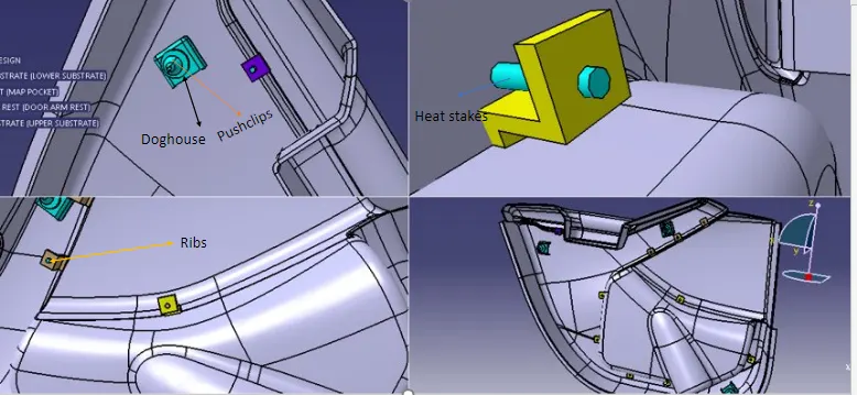
Ribs : Ribs are indispensable functional structures on many plastic parts. It can effectively improve the rigidity and strength of plastic parts like the H beam. By using ribs, it is not necessary to greatly increase the wall thickness of the plastic parts, and ribs are not undercut structures like the H beam whose structure will be difficult to make for plastic injection molding.
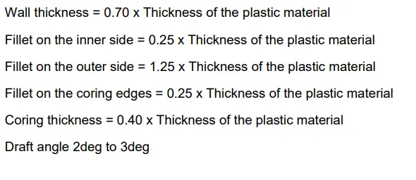
Doghouse : Dog house is an engineering features used in plastic trim design. Dog houses are used as supporting feature. Sometimes other engineering features like snaps; locators etc. are mounted on them to increase their strength. Dog houses are subjected to draft analysis to prevent breakage of the component during ejection from mould cavity.
Heat stakes : Heat Staking also known as thermoplastic staking is the process of joining two dissimilar materials together. In heat staking we use local heating and cooling to raise the temperature of plastic components and allow plastic reforming to be carried out. This reforming can be used in a wide variety of applications.
Doghouse design considerations :
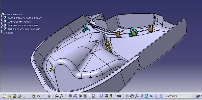
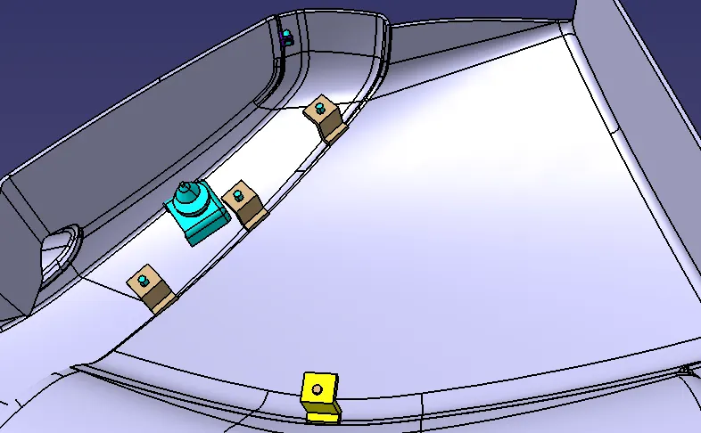
Draft analysis for B side features doghouse , heat stakes and ribs .
The areas which are highlighted in green can be ejected normal draft degree of injection moulding
Areas with red and blue slider and lifter axis to eject and clear the tooling direction.
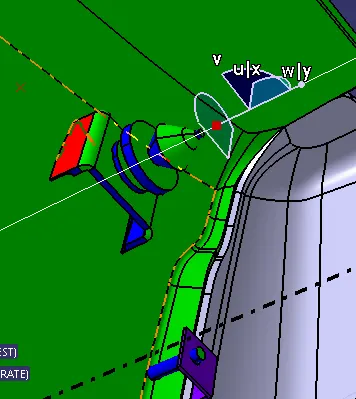
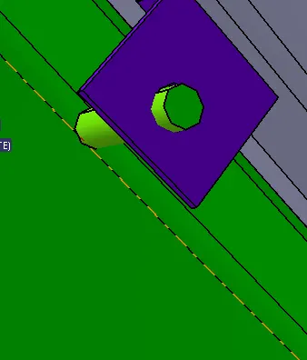
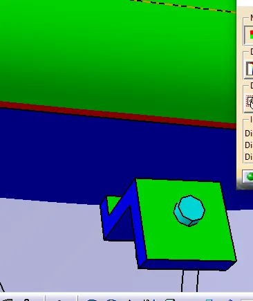
Complete Draft analysis of the door trim design :
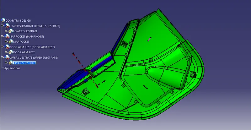
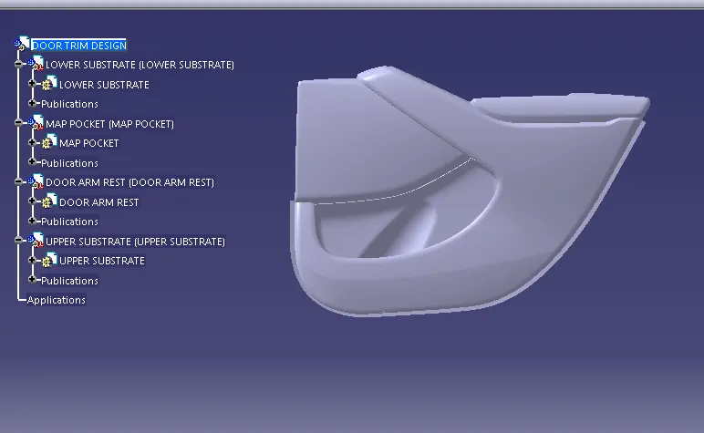
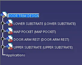
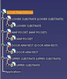
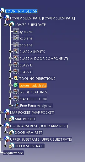
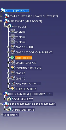
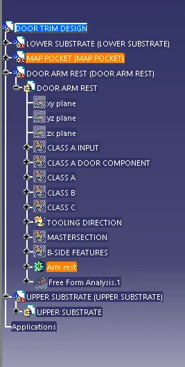
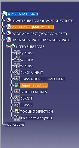
TREE STRUCTURE OF THE DESIGN :
.Collapsing all
CONCLUSION :
Thus,the final output is obtained using class A input we have developed class B and class C ,draft analysis ,tooling direction and closed body with bside features as per the guidelines of OEMs and tier 1companies,Now the door interior trim is ready to manufacture .
REFERENCE : https://skill-lync.com/
https://www.sidotek.com/ribs-and-bosses-design-guidelines-in-plastic-parts/