Week 11 - Final project
REPORTING FOR THE FINAL PROJECT:
- Input Files opened in Catia.
- Form the MASTER_SECTION_DEVELOPMENT_SEPERATED_MODEL.
- In Assmbly workbench, this part is opened as existing part.
- Then New Product is insertd, as RH_DOOR_ASSEMBLY1.
- In this assemblt nee Parts are inserted for easch Surface in INput.
- Named as
Arm Rest1., Body1, Body2, and Bin1.
each part is with respective surface geometry.
RH_DOOR_ASSEMBLY1 is now opend in new window.
Started working on each part, with Body1 at first.
Tooling axis created using line normal to surface option and performed draft analysis, major surface is clearing draft analysis except a cornar and fillet area.
Hence created anothe rtooling axis using biection method and performed Draft analysis once agin, but same area was not clearing draft analysis.
Part body:
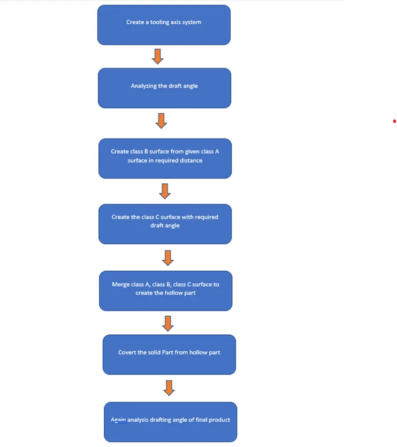
On a broad spectrum, the automotive design process can be split up into four stages:
- Concept
- Sketch
- Class A Surface (CAS)
- Computer-Aided Design (CAD)
An automotive vehicle concept is first hypothesized or envisioned by an artist, designer, or engineer, which is then sketched onto a paper. Once an idea is approved, it moves on to the computer where it is rendered in 2D.
Then, the Class A Surfaces are built. This is followed by a complete 3D CAD modelling of the automotive vehicle, including photorealistic renders, which later goes into mass production.
On a higher level, the product development process can be summarized as follows:
- Styling theme and approval CAS
- Preliminary design
- Preliminary analysis
- Final style approval
- Detail design
- Verification
- Development
- Prototype build
- Design validation
- Plot production
- Launch and mass production
Concept Sketch: Pre hand drawing done on a paper later converted to styling Class A which is basically done by software like ALIAS.
Design validation determines whether the design fulfills the intended purpose
Feasibility check is to determine the practicability of a design.
Concept validation is the stage of validating the design and possibility.
Before mass production any corrections will be corrected.
TOOLS:
- Extract:
This comment is used to create the required surface again. Which means copy the surface again for next operations.
- Un trim:
This tool is used to un trim the surface which means create the full surface of previous surface from current surface.
- Trim:
This tool is used to cut and eliminate the unwanted surface.
- Extrapolated:
This tool is used to increase the length of surface or area with the help of different option.
- Offset:
It is used to create the same surface again in required distance.
- Edge Fillet:
It is used to create sharp edges to round edges.
- Boundary:
It is used to form the boundary lines on opened surface.
- Sweep:
It is used to create the surface in required length from the profile.
- Join:
It is used to join the separate surfaces and create the single surface.
- Close (Part command)
It is used to create the solid part from closed hollow part.
- Curve smooth:
It is used to change the smooth curve from tangency curve.
- Fill:
Fill some gaps portion with this comment
- Blend:
Two bounty lines used to fill the gaps by this comment.
14.Split:
It is used separate the surface with the help of another surface as cutting tool.
- Pad:
It is used to extrude to create 3D part from 2D sketch.
16.Thicken:
It is used to give thickness of the surface model. It is one of the part bench comments.
DESIGN LIFE CYCLE
It Involves
Concept sketches
Class A creation
Clay modeling
NPD CAD
Concept sketches which are fed into computer as 2D sketches
Class A: The dedicated Class A Surface creation software helps turn a sketch into a surface that can be controlled in a three-dimensional virtual space. One would typically require three images, i.e., the front view, side view, and top view.
Class A and clay modeling are inter related. Clay model is the one to one model of vehicle both interior and exterior would be made for realistic display.
NPD CAD – New product development is where the designing parts for assembly with dimensions takes place.
Now we are going to work in new product development phase for the given Input.
Materials details
Interior Trims are manufactured by Poly propylene (PP), Acrylonitrile butadiene styrene (ABS), Poly vinyl chloride (PVC).
Since plastic in light in weight, economic effectiveness wide variety of plastic are used. It also gives good aesthetic surface.
CLASS A CREATION:
From the given Input the respective class A class A surface are created by joining the surfaces. Check for continuity of the surface.
Hence started with the tooling Axis , created using bisecting method.
CLASS A SURFACE:
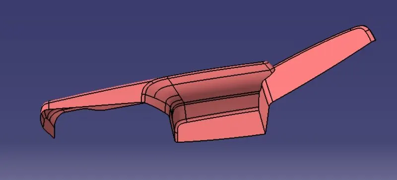
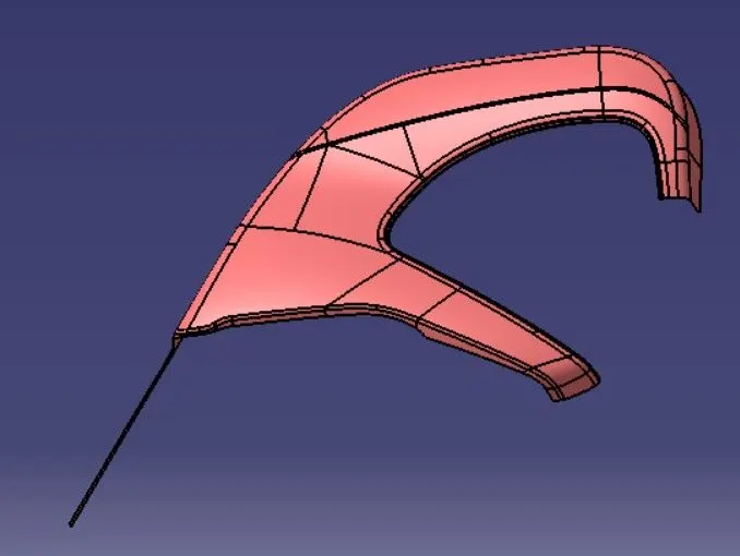
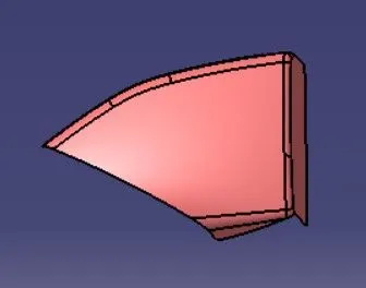
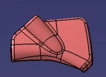
These are the all CLASS A surfaces from the project.
We need to work from Class A to Class C.
Class A is the Asthetic Material where we can see with your naked eyes and simply we can say that it is an exterior part of the product.
Class B is the Innside Material where we are working inside the body.
Class C means which we join the both class A and class B.
TOOLING AXXIS:
The tool axis is a rotated an Angle 1 about the x-axis, then rotated an Angle 2 about the y-axis. The tool axis is a rotated an Angle 1 about the z-axis, then rotated an Angle 2 about the x-axis. The tool axis is a rotated an Angle 1 about the y-axis, then rotated an Angle 2 about the z-axis.
Tooling axis: The direction in which the mold or core and cavity opens is the tooling axis. STEP-01. Connectivity of Class-A surface: Checking the connectivity of the surface, this can be done by creating boundaries or by simply using the join option such that any openings can be easily visualized.
The Tooling Direction is basically the direction that the mold pulls apart. The mold is built in two separate pieces, basically. You have a Cavity side and you have the Core side. The Core pulls apart from the Cavity and that's the Dyeline or the Tooling Direction.
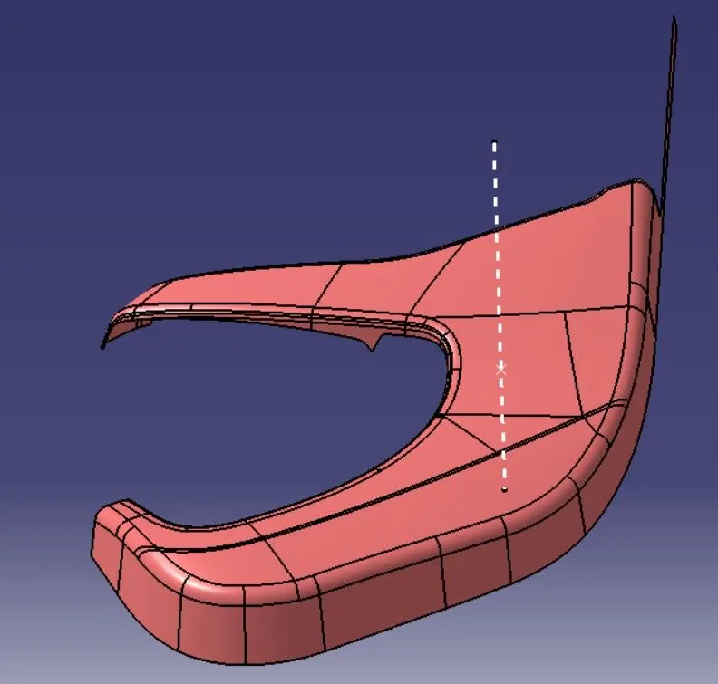
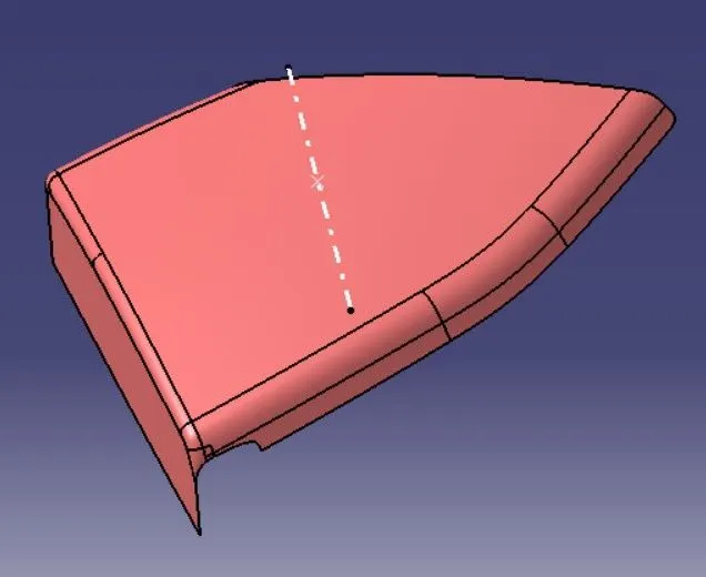
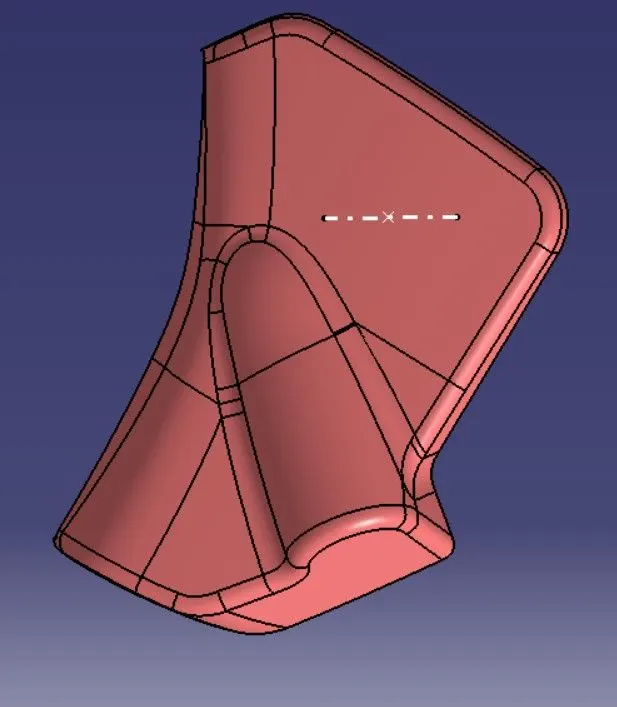
The above fig shows how the tooling direction will be placed.
We dont want to take the tooling axis directly we need to extract the part and we need to create the tooling axis.
The tooling axis will shows the entire part of the model it visualization will be more clear.
CLASS B SURFACE CREATION-
B surface is the engineering surface where all the b side features like rib, dog house screw boss, and locator and heat stake are designed.
The class A surface is offset to 2.5 mm to get the b surface.
Input class A surface is offseted to 2.5mm.
It was perfectly offseted.
Extrapolated boundary of class B surface by 0.5 mm.
CLASS C SURFACE CREATION-
As class C sueface is Perpendicular to Tooling axis, Sweep Normal to surface selected for creation.
Complete C surface was not possible in a single sweep, hence it is co,[leted in parts. and joined to a single C surface.
Next Step Class A and Class C surfaces are joind and trimmed with extrapolated B surface to get a closed surface.
This closed body is cinverted to Part body.
C surface is the surface which connects the A surface and B surface along the tooling direction.
In door arm 1 the class A boundary is swept with reference to the surface and door arm is swept in direction of tooling axis.
In lower substrate the class A and B surface boundaries are multi sectioned and A-b-c surface are joined together to get a closed surface.
In map pocket the swept is done in draft direction.
After c surface creation class A, B and C surface are joined together to get a closed surface.
To check click boundary and see whether boundary is forming, if it is showing error then we got a closed surface.
Then switch to part design and given closed surface to form the solid part body.
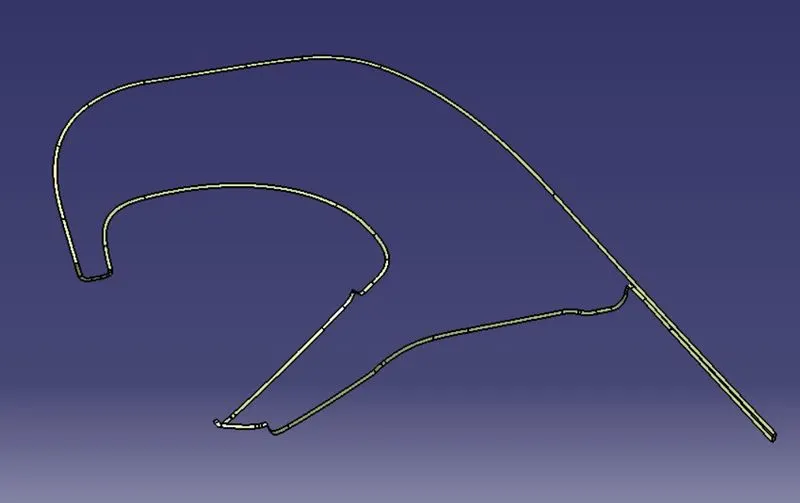
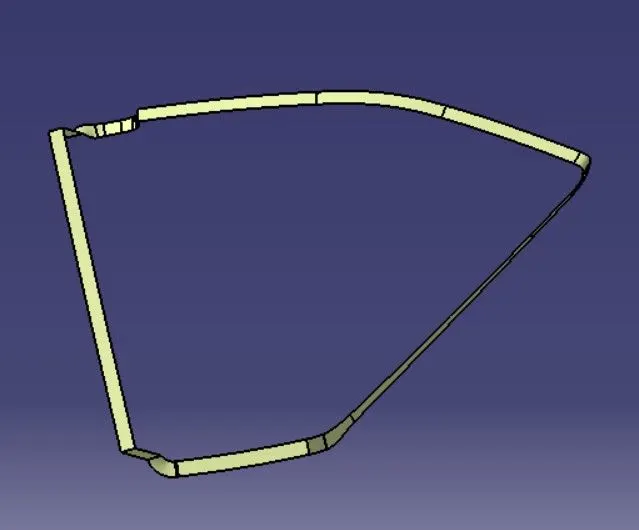
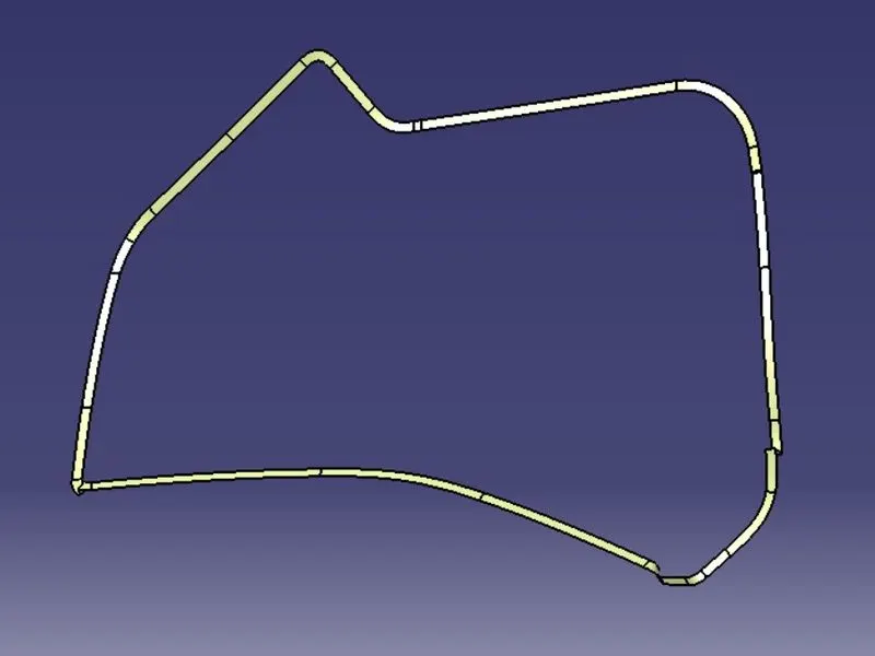
These are the class C surfaces where it took from the class A boundary.
Here we use the class A and class C joining and we use TRIM command to get accurate position.
After creating the class C we are going to join with the class A and class C.
B SIDE FEATURE CREATION
For the attachment strategy master section is given from which we have to create the b side features at respective surfaces.
Master sections are the guides for the design requirements which decide the component packaging after technical surfaces.
During the period of vehicle concept design, the evaluation of master section performance depends on reference vehicle data and the experience of structure design engineer
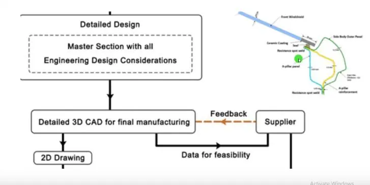
In door trim panel we are going to create heat stakes, dog house, Flanges and ribs
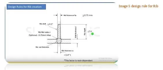
Ribs: Ribs provide a means to economical stiffness and strength in molded parts without increasing overall thickness. They also facilitate locating and arresting components of an assembly, provide alignment and act as stops or guides for mechanism
Doghouse Creation
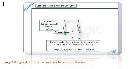
Dog house: Dog house is an engineering feature used in plastic trim design which is used as a supporting feature. Other features like locator are mounted on them to increase strength. They prevent breakage of the component during ejection.Ribs are given for dog house. Push clip is mounted on the dog house .
the sketches are drawn with positiones and iso constrained.
Map Pocket and Lower Subtrate need Dog houses.
1 Dog house for Map pocket
2 dog houses for lower subtrate.
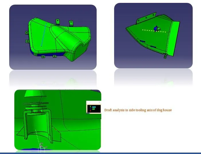
Draft Analysis-Inner surfaces along slider axis.
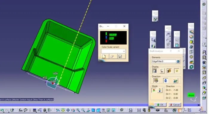
For the dog house we need to create the side core axis and main tooling axis.
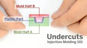
Slider is used for the EXTERNAL UNDER CUTS of the model .
Lifter is used for INTERNAL UNDER CUTS of the model.
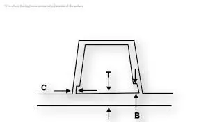
Design CLaculations For Dog house-
Thickness DGH= T=2.5 mm
Height = 20 mm
MIn thickness at joint of B surface = C= 0.4 X 2.5 = 1 mm.
Height of C =H= between 3 to 6 mm .
Creation of Flanges From Master Section-
Two types of flanges are there. For arm rest side and Map Pocket side. They are created as per reference.
width of Flange is 30 mm. Distance between two consecutive flanges maintained minimum 50 mm.
Thickness is 2.5 mm.
NO master section provided for Bottle holder side, Hence created flat support for heaat stakes in this area.
Heat Stakes Creation-
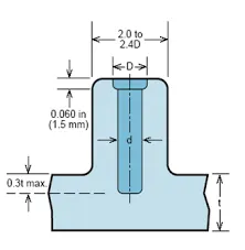
Heat stakes: Heat stakes are used to join components of similar or dissimilar material.
From Master section, Heat stakes are created with OD 7.5 mm, and ID 4.5 mm.
Height is considered as required to cross lower subtrate.
Master Section was created as separate Part. hence I created all flanges, and Heat Stakes in thos Part and By usinf copy Paste Special, All the components Union Trimmed with respective parts.
Thermal staking is an assembly method that uses the controlled melting and reforming of a plastic or metal component of an assembly in place. The plastic stud protrudes through the hole in the component to be locked in place.
Assembly-
Push Pin was provided as Input.
Need to assemble push pin with 3 dog houses. Using Coincidance constraint, the push pins and dog house connected.
Drafting: Draft is providing angles or tappers on product feature such as walls, ribs and bosses that lie parallel to the direction of release from the mold that eases part ejection.
Adding draft helps the part to release. Most parts or applications require a minimum of 0.5 degree to 1 degree however 3 degree is widely accepted as the norm.
Ideal draft for a component is 3 degree.
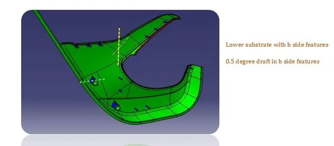
Minimum 0.5 degree is accepted in b side features.
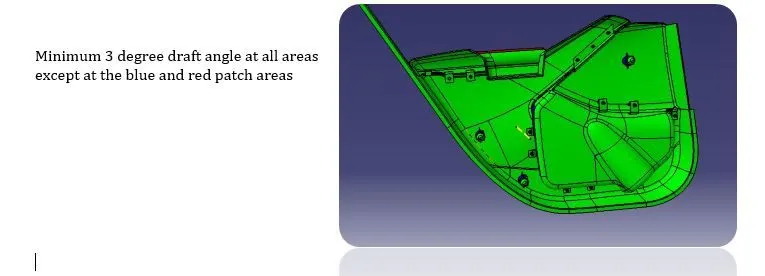
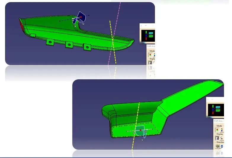
Draft analysis is done along the tooling axis for class and final part body.
Draft = 1.5 degree, outer walls. with Main tooling Axis
Draft = 0.5 degree. inner walls , with lifter axis.
change the view mode to customize view parameters mode -then go to inser -analysis-feature draft analysis.Place compass on the respective tooling axis.Th draft analysis is formed.green above 3 degree blue 0-3 degree red -negative draft
PROCEDURE:
Drag the compass and place it over to the line. Select the compass icon from the direction of the Draft Analysis dialog box. The compass may get misplaced from its original position after clicking on the compass icon. Select the compass again and place it over to the line properly one more time.
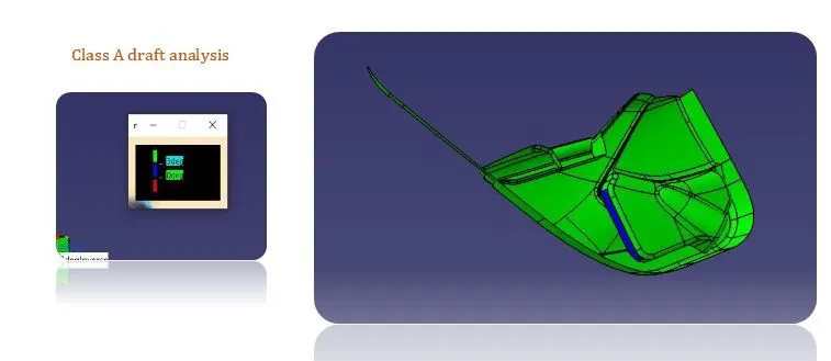
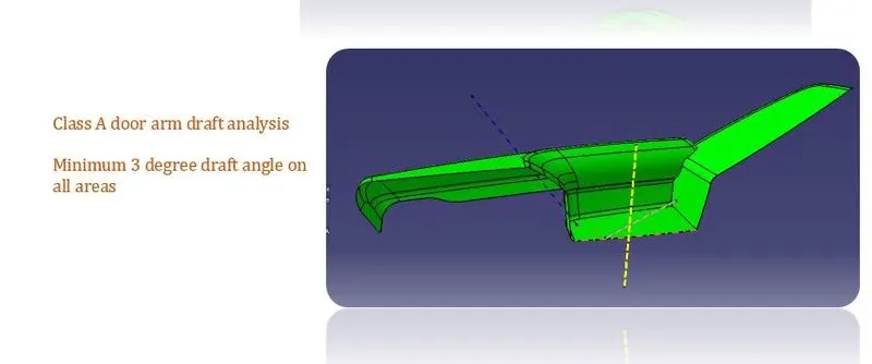
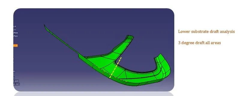
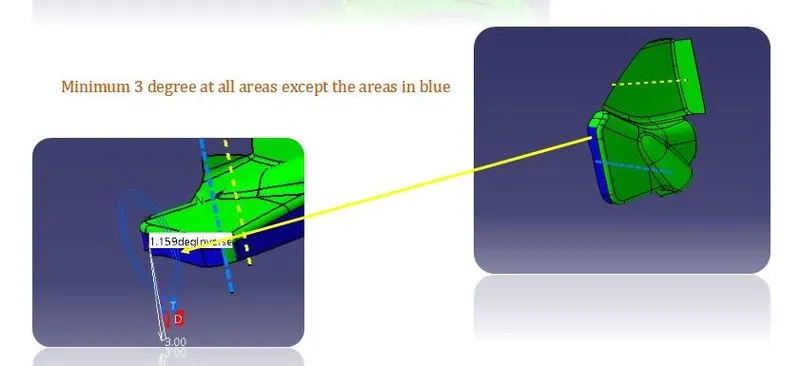
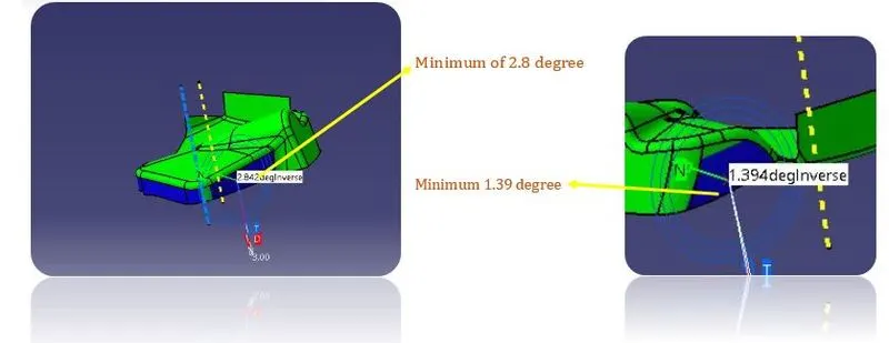
Soli part body draft analysis.
Creation of Flanges From Master Section-
Two types of flanges are there. For arm rest side and Map Pocket side. They are created as per reference.
width of Flange is 30 mm. Distance between two consecutive flanges maintained minimum 50 mm.
Thickness is 2.5 mm.
NO master section provided for Bottle holder side, Hence created flat support for heaat stakes in this area.
Heat Stakes Creation-
Heat stakes: Heat stakes are used to join components of similar or dissimilar material.
From Master section, Heat stakes are created with OD 7.5 mm, and ID 4.5 mm.
Height is considered as required to cross lower subtrate.
Master Section was created as separate Part. hence I created all flanges, and Heat Stakes in thos Part and By usinf copy Paste Special, All the components Union Trimmed with respective parts.
Thermal staking is an assembly method that uses the controlled melting and reforming of a plastic or metal component of an assembly in place. The plastic stud protrudes through the hole in the component to be locked in place.
Assembly-
Push Pin was provided as Input.
Need to assemble push pin with 3 dog houses. Using Coincidance constraint, the push pins and dog house connected.
About Material Selection:-
About Requirements-
Interior parts that contain the most controls and decorative parts.
It is necessary to balance gap between parts, as well as an overall sense of unity between the numerous parts.
Interior trim parts are extremely diverse. Each part has a certain level of functionality as well as aesthetic appeal.
As in current project, Right Hand side Door-
following properties are required
Good Surface finish
high dimensional stability
Good abrasion and strain resistnace
Rigidity
Impact Resistnace-
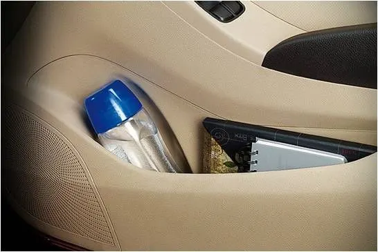
BOTTLE HOLDER-MAP POCKET-
Made of ABS plastic, ABS material is having all the qualities.
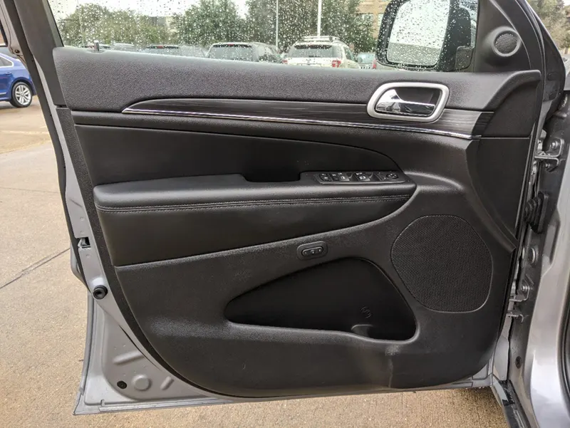
ARM REST-
An armrest should be made of very durable materials as it wear out the fastest.
Also it should provide comfortable support – Neither too hard such that, it may cause discomfort nor too soft, as it may provide poor hand stability.
Expanded polypropylene (EPP) is the best option, as it does not undergo permanent deformation and returns to its previous shape after the pressure has ceased.
Door Trim- Require
high Impact resistance.
high dimensional stability
Good abrasion and strain resistnace
Rigidity
Light weight
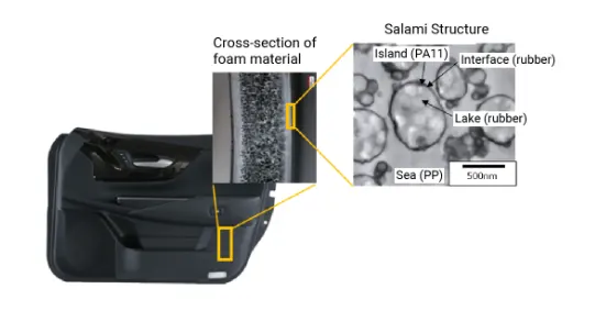
Generally ABS is used. But for more strength and impact resistance, foam is also composed with traditional material to reduce weight and achieve highe impact resistance.