Week 11 - Final project
DEVELOPMENT OF DOOR TRIM PANEL
Aim :
To create a CAD model (Door Trim Panel) with attachment features considering the given inputs, design rules and following the OEM standards.
Objectives :
- To extract all the necessary surfaces like class B and C.
- To capture the complex areas properly and make sure the drat is done.
- To capture all the attachment features like ribs, snap, heat stakes, 4-way locator, dog house, etc.
- To make sure the part is feasible and possible to manufacture at the same time economical and weight is also considered.
Abstract :
The project report deals with the explanation of steps and procedure followed while developing the Door Trim Panel of a car using CATIA V5. Using the CLASS-A surface and master sections as input, we were able to create a Tooling axis, CLASS-B surface, CLASS-C surface, Flanges and form a solid body after which the attachment features such as Dog House, Push Pins, Heat stakes, etc are created. To check the manufacturability of the parts, a Draft Analysis has also been performed using the main/side tooling axis on various components such as lower substrate, map pockets, armrest, etc.
Methodology :
- CLASS-A surface extraction
- Creation of different Geometrical sets for each component such as lower substrate, map pocket (upper & lower part), armrest (upper & lower part), etc.
- Tooling Axis / Side Core Axis Creation
- Creation of Flanges
- Creation of CLASS-B Surface
- Creation of CLASS-C Surface
- Joining of CLASS-A, B & C Surface
- Performing a check for boundaries
- Forming a Solid Body
- Attachment features creation
- Performing Draft Analysis
Automotive Plastic Trim:
The design of Automotive Interior and Exterior plastic components is called Trims. The plastic components that you see inside the car are Interior. Ex: Dashboard, Instrument Panel, Doors, seating, and pillars. Plastic components that you see outside of a car are Exterior. ex: bumper, light assembly, hoods.
Door Trim:
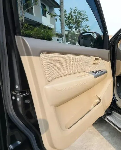
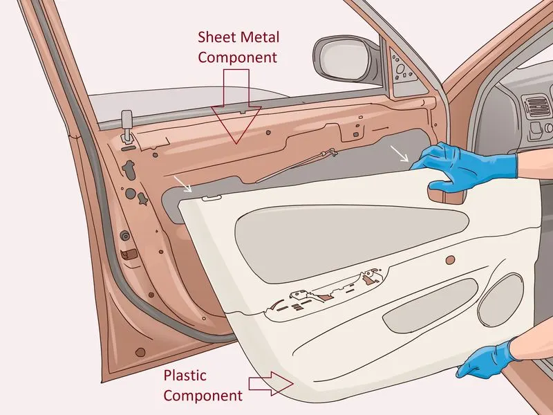
The door panel covers internal parts like the window regulator, the power window motor, and the wiring. It is attached to the sheet metal part of the door. It is designed differently based on the design of the sheet metal part of the door. Besides its aesthetic look, it also has many functional features attached to it such as an armrest, bottle holder, speaker attachment, etc. In older cars, door panels used to be made out of cardboard and upholstered with material that matches the rest of the upholstery within the cabin. On the other hand, most modern cars have door panels made from plastic. The main materials used include kenaf, which grows year-round and has excellent CO2 absorbing properties, and plant-derived plastic, making them environmentally friendly as well.
Introduction:
10 Stages of Product life cycle of automotive Industry are
1. Concept sketch
2. Styling class A
3. Feasibility check
4. Concept validation
5. New Product Design
6. Product Development
7. Proto Build
8. Design Validation
9. Pilot Production
10. Mass production
5. New Product Development CAD :
This is the stage where the major work of product design, by taking inputs from the concept sketch to validate the product will go to design using design software such as Nx, catia, solidworks, solid edge etc. IN this stage through design all the surfaces are divided into sub parts from the class A surface and Ensuring product should be workable. Making the 3D model and 2D drawings for development. Here product design is going to complete 100%.
Example: Designing the car surface with the help of class A and clay model here designer going to detail producing the model from the point of manufacture, assembly etc , shown in the fig6.4
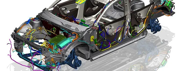
Door panels serve as an interface between the interior of the car and the inner workings of the door, and between vehicle occupants and the door. They are expected to meet a variety of design specifications regarding safety, aesthetics, and functionality. In addition, they are expected to continue the material theme of the dashboard and pillars while concealing intricate electrical and mechanical components for operating locks, windows, and other features.
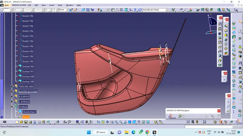
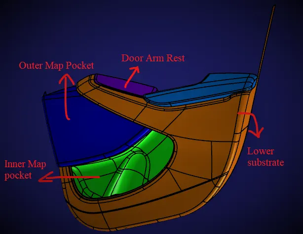
In this project, an inner car door panel is given with class A surface, to create the door trim panel it is divided into sub-parts namely, a lower substrate, inner map pocket, outer map pocket, and door armrest.
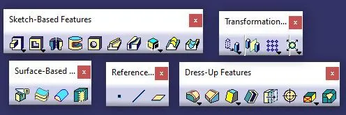
Tools Used:
Part workbench:
Surface Workbench:

Given input:
Sub Division:
Dividing the given surface into 4 parts to prepare each part individually for manufacturing and then assembling. The parts are created according to the master section given along with input.
For this particular project parts to be formed are as follows:
- Door armrest
- Lower substrate
- Outer Map pocket
- Inner Map pocket
1. Door Armrest :
Frequently there is a further armrest built into the door of the car, often forming part of the door pulling handle. Rear. A rear armrest will typically fold away between the back seats, to allow for the central (third) seating place to be used.
Given Class A Surface :
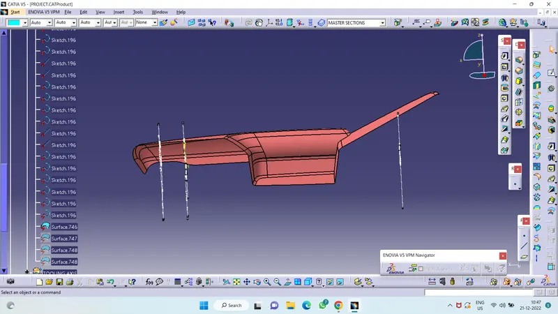
- Class A:
- In automotive design, a class A surface is any of a set of freeform surfaces of high efficiency and quality.
- Class A surfacing is done using computer-aided industrial design applications. Class A surface modellers are also called "digital sculptors" in the industry. Industrial designers develop their design styling through the A-Surface, the physical surface the end-user can feel, touch, see etc.
- A common method of working is to start with a prototype model and produce smooth mathematical Class A surfaces to describe the product's outer body. From this, the production of tools and inspection of finished parts can be carried out. Class A surfacing complements the prototype modelling stage by reducing time and increasing control over design iterations.
- Class A surfaces can be defined as any surface, that has styling intent, that is either seen, touched,
Tooling axis Creation :
In injection molding, the Class A surface is first analyzed to determine the axis or tooling direction that separates the molds. Tooling direction is critical for plastic product design because it determines mold direction.
TOOLING AXIS USING BISECTING METHOD :
Tooling axis for the part is created by using the dummy tooling axis using the bisectiong method .In order to check whether the part is toolable in the direction,the class A surface is analysed and the walls which are doubtful of clearing the 3 degree draft angle to the dummy tooling axis is identified.
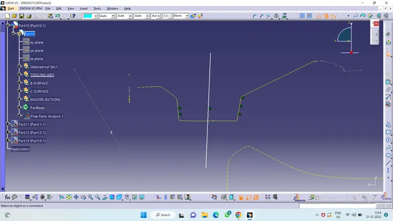
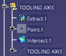
Tree Structure of Tooling Axis :
- Class B:
- Class B is the one surface that is mostly used to capture the 2nd half of the part, it is the part that splits into the mould.
- Class B surfaces are the secondary surfaces that you can see sometimes, but are less important, such as the inside of your glove box, ashtray, etc. These must be smooth and "error-free" as well but are not held to the standards that class A surfaces are.
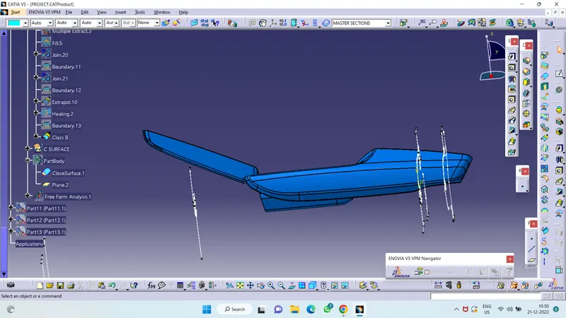
- Class C surfaces:
- These are the backside surfaces that can have tool marks, flash and other imperfections without hurting appearance, function, etc.
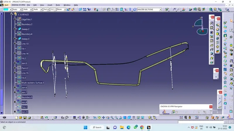
Class (A+B+C) Surface Body :
Here we combine all the surfaces into one closed surface using the Trim tool Command.
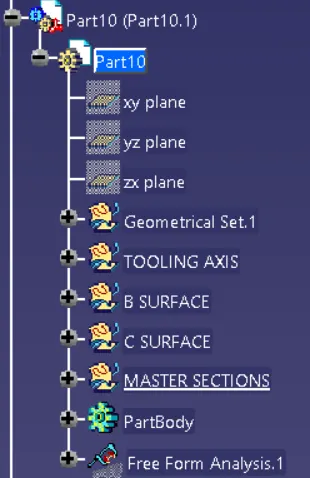
Tree Structure :
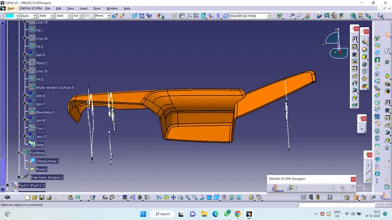
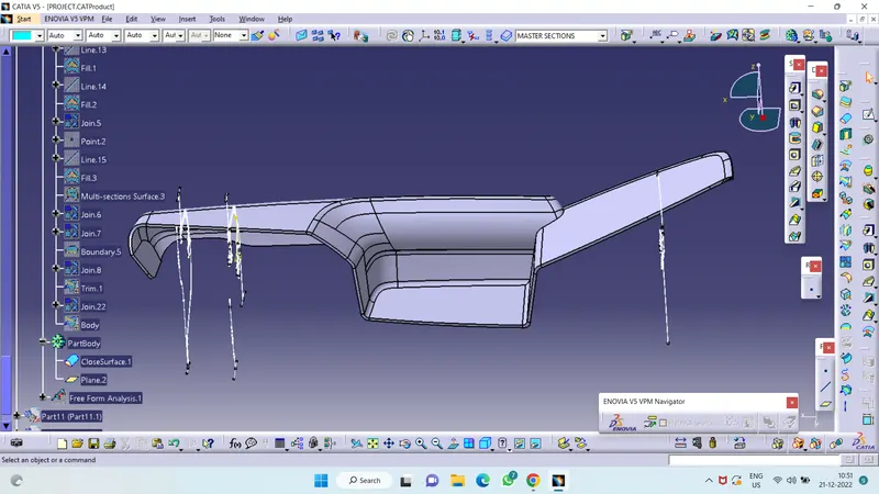
Close Body Surface :
Draft Analysis
For molded or cast parts, the draft angle is the amount of taper perpendicular to the parting line. It is measurable in degrees. Because plastic shrinks and sticks on molding surfaces as it cools, we draft the walls of the plastic part so that it ejects or breaks free from the molding surfaces more easily and without dragging. To reduce the risk of damage to the parts and ensure ejection, a functional injection molding part must have drafts on both the cavity and core sides.
Nominal values for Draft angles
- 3 Degrees is a nominal draft angle
- 5 Degrees can also be manufactured. Increasing the manufacturing cost
- 7 Degrees is considered for Textured surface parts
Importance of Draft in injection molding
- Reduces the possibility of part damage due to friction during the release
- Reduces mold wear and tear
- Ensures a uniform, smooth, unscratched finish
- Ensures the integrity and uniformity of other surface finishes and textures
- Reduces overall cooling time by reducing or eliminating the need for unusual ejection setups
Steps followed for Draft Analysis
- The created part must be changed to the material mode in the display frame
- Compass is enabled and placed in the direction of the Tooling Axis
- The lock command is then used to fix the compass along the tooling axis
- Colour codes are classified and Draft angle is applied
- Running point analysis is used to display permissible draft angle
Draft Analysis of Class A Surface :
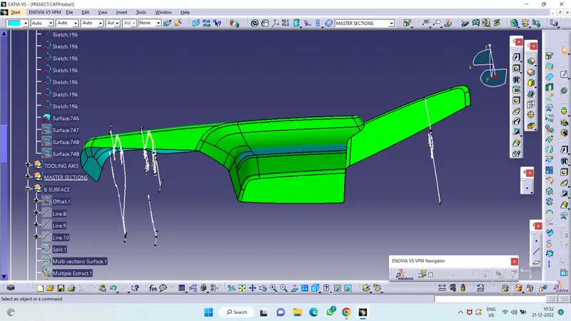
Draft Analysis of Close body Surface :
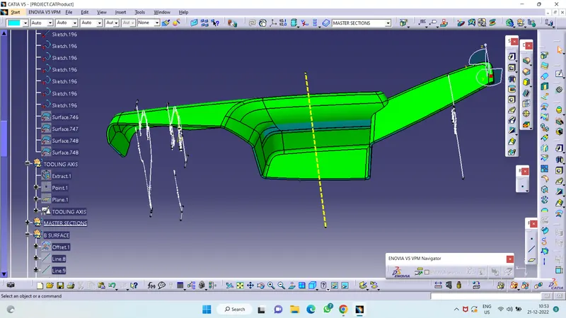
Analysis shows the drafted walls of the base bracket are above 3 degrees which is permissible for manufacturing in injection molding
2. Lower substrate :
Given Class A Surface :
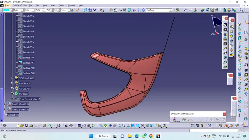
- Class A:
- In automotive design, a class A surface is any of a set of freeform surfaces of high efficiency and quality.
- Class A surfacing is done using computer-aided industrial design applications. Class A surface modellers are also called "digital sculptors" in the industry. Industrial designers develop their design styling through the A-Surface, the physical surface the end-user can feel, touch, see etc.
- A common method of working is to start with a prototype model and produce smooth mathematical Class A surfaces to describe the product's outer body. From this, the production of tools and inspection of finished parts can be carried out. Class A surfacing complements the prototype modelling stage by reducing time and increasing control over design iterations.
- Class A surfaces can be defined as any surface, that has styling intent, that is either seen, touched,
Tooling axis Creation :
In injection molding, the Class A surface is first analyzed to determine the axis or tooling direction that separates the molds. Tooling direction is critical for plastic product design because it determines mold direction.
TOOLING AXIS USING BISECTING METHOD :
Tooling axis for the part is created by using the dummy tooling axis using the bisectiong method .In order to check whether the part is toolable in the direction,the class A surface is analysed and the walls which are doubtful of clearing the 3 degree draft angle to the dummy tooling axis is identified.
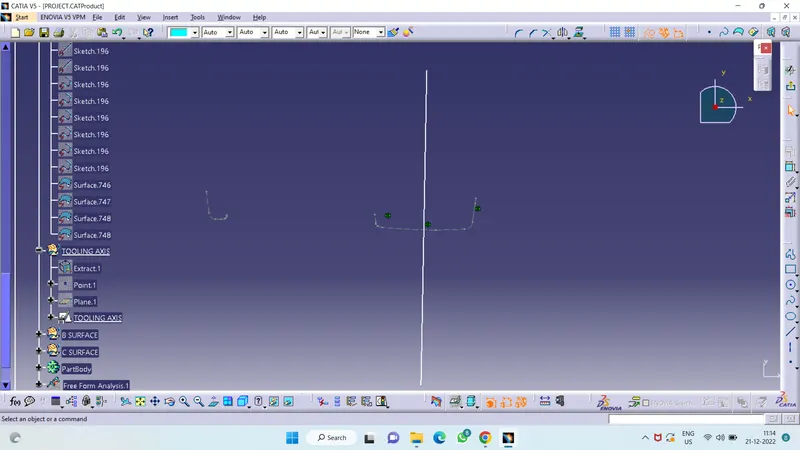
Tree Structure of Tooling Axis :
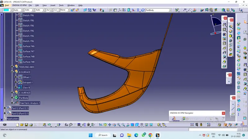
- Class B:
- Class B is the one surface that is mostly used to capture the 2nd half of the part, it is the part that splits into the mould.
- Class B surfaces are the secondary surfaces that you can see sometimes, but are less important, such as the inside of your glove box, ashtray, etc. These must be smooth and "error-free" as well but are not held to the standards that class A surfaces are.
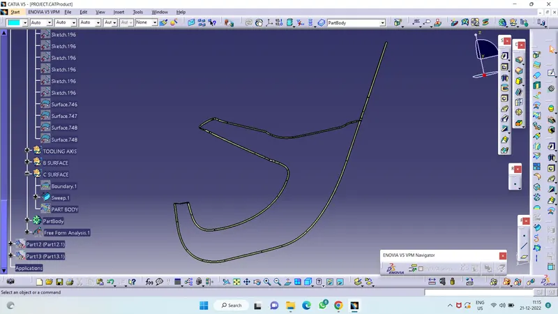
- Class C surfaces:
- These are the backside surfaces that can have tool marks, flash and other imperfections without hurting appearance, function, etc.
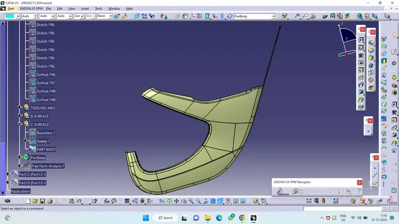
Class (A+B+C) Surface Body :
Here we combine all the surfaces into one closed surface using the Trim tool Command.
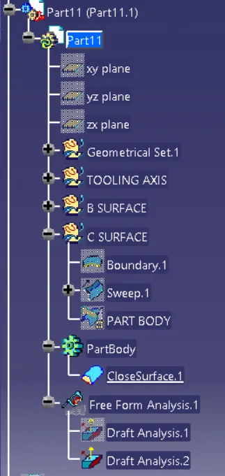
Tree Structure :
Close Body Surface :
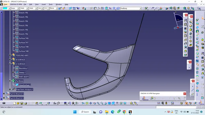
Draft Analysis
For molded or cast parts, the draft angle is the amount of taper perpendicular to the parting line. It is measurable in degrees. Because plastic shrinks and sticks on molding surfaces as it cools, we draft the walls of the plastic part so that it ejects or breaks free from the molding surfaces more easily and without dragging. To reduce the risk of damage to the parts and ensure ejection, a functional injection molding part must have drafts on both the cavity and core sides.
Nominal values for Draft angles
- 3 Degrees is a nominal draft angle
- 5 Degrees can also be manufactured. Increasing the manufacturing cost
- 7 Degrees is considered for Textured surface parts
Importance of Draft in injection molding
- Reduces the possibility of part damage due to friction during the release
- Reduces mold wear and tear
- Ensures a uniform, smooth, unscratched finish
- Ensures the integrity and uniformity of other surface finishes and textures
- Reduces overall cooling time by reducing or eliminating the need for unusual ejection setups
Steps followed for Draft Analysis
- The created part must be changed to the material mode in the display frame
- Compass is enabled and placed in the direction of the Tooling Axis
- The lock command is then used to fix the compass along the tooling axis
- Colour codes are classified and Draft angle is applied
- Running point analysis is used to display permissible draft angle
Draft Analysis of Class A Surface :
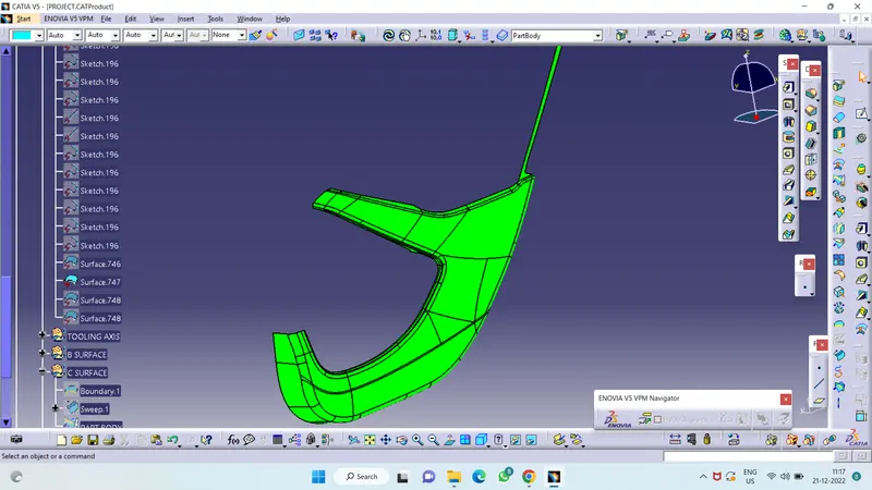
Draft Analysis of Close body Surface :
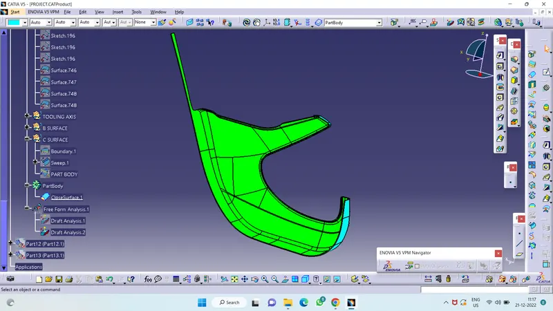
Analysis shows the drafted walls of the base bracket are above 3 degrees which is permissible for manufacturing in injection molding.
3. Outer Map pocket :
Given Class A Surface :
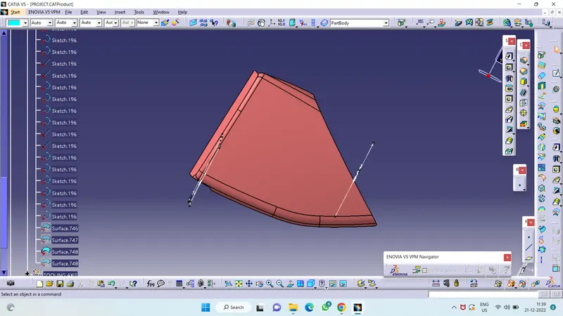
- Class A:
- In automotive design, a class A surface is any of a set of freeform surfaces of high efficiency and quality.
- Class A surfacing is done using computer-aided industrial design applications. Class A surface modellers are also called "digital sculptors" in the industry. Industrial designers develop their design styling through the A-Surface, the physical surface the end-user can feel, touch, see etc.
- A common method of working is to start with a prototype model and produce smooth mathematical Class A surfaces to describe the product's outer body. From this, the production of tools and inspection of finished parts can be carried out. Class A surfacing complements the prototype modelling stage by reducing time and increasing control over design iterations.
- Class A surfaces can be defined as any surface, that has styling intent, that is either seen, touched,
Tooling axis Creation :
In injection molding, the Class A surface is first analyzed to determine the axis or tooling direction that separates the molds. Tooling direction is critical for plastic product design because it determines mold direction.
TOOLING AXIS USING BISECTING METHOD :
Tooling axis for the part is created by using the dummy tooling axis using the bisectiong method .In order to check whether the part is toolable in the direction,the class A surface is analysed and the walls which are doubtful of clearing the 3 degree draft angle to the dummy tooling axis is identified.
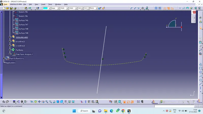
Tree Structure of Tooling Axis :
- Class B:
- Class B is the one surface that is mostly used to capture the 2nd half of the part, it is the part that splits into the mould.
- Class B surfaces are the secondary surfaces that you can see sometimes, but are less important, such as the inside of your glove box, ashtray, etc. These must be smooth and "error-free" as well but are not held to the standards that class A surfaces are.
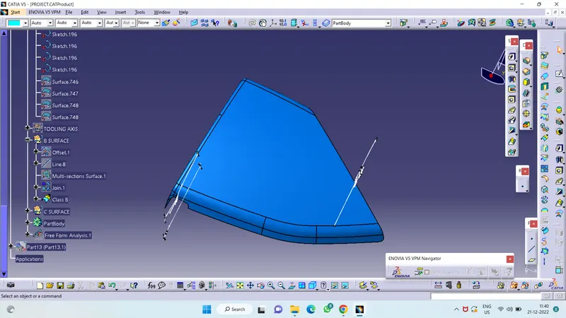
- Class C surfaces:
- These are the backside surfaces that can have tool marks, flash and other imperfections without hurting appearance, function, etc.
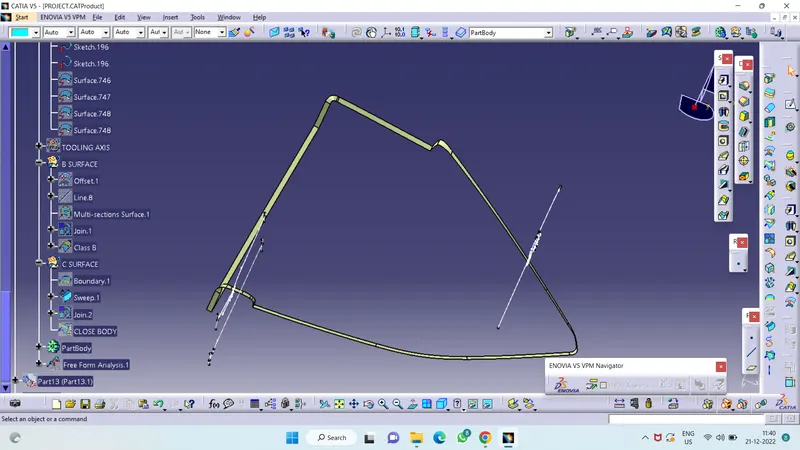
Class (A+B+C) Surface Body :
Here we combine all the surfaces into one closed surface using the Trim tool Command.
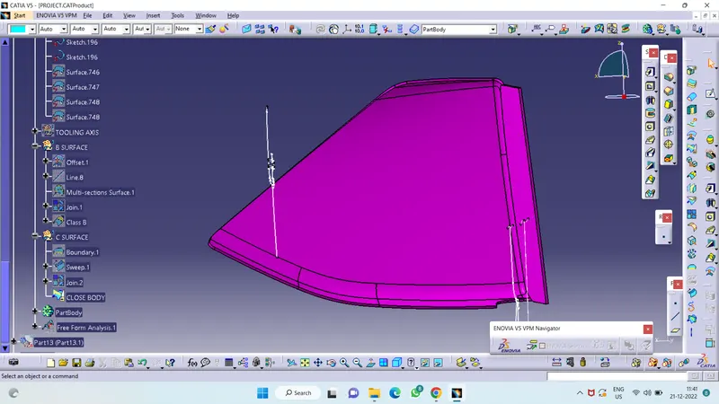
Tree Structure :
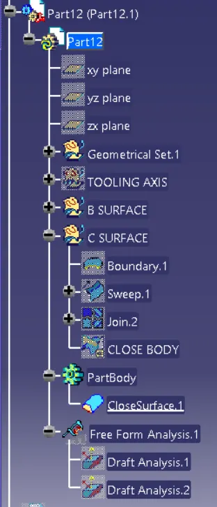
Close Body Surface :
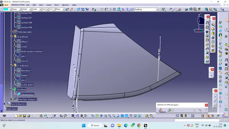
Draft Analysis
For molded or cast parts, the draft angle is the amount of taper perpendicular to the parting line. It is measurable in degrees. Because plastic shrinks and sticks on molding surfaces as it cools, we draft the walls of the plastic part so that it ejects or breaks free from the molding surfaces more easily and without dragging. To reduce the risk of damage to the parts and ensure ejection, a functional injection molding part must have drafts on both the cavity and core sides.
Nominal values for Draft angles
- 3 Degrees is a nominal draft angle
- 5 Degrees can also be manufactured. Increasing the manufacturing cost
- 7 Degrees is considered for Textured surface parts
Importance of Draft in injection molding
- Reduces the possibility of part damage due to friction during the release
- Reduces mold wear and tear
- Ensures a uniform, smooth, unscratched finish
- Ensures the integrity and uniformity of other surface finishes and textures
- Reduces overall cooling time by reducing or eliminating the need for unusual ejection setups
Steps followed for Draft Analysis
- The created part must be changed to the material mode in the display frame
- Compass is enabled and placed in the direction of the Tooling Axis
- The lock command is then used to fix the compass along the tooling axis
- Colour codes are classified and Draft angle is applied
- Running point analysis is used to display permissible draft angle
Draft Analysis of Class A Surface :
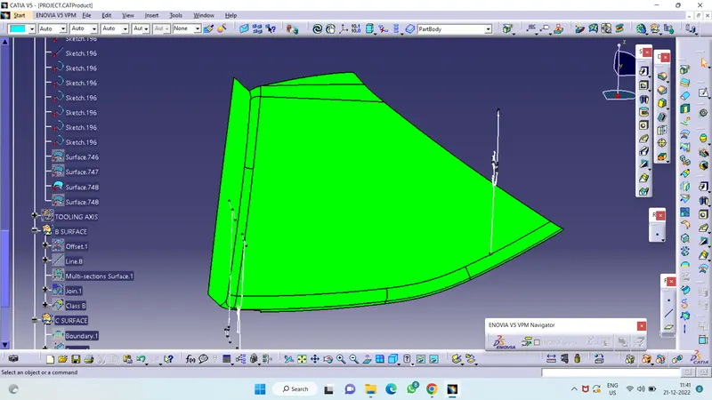
Draft Analysis of Close body Surface :
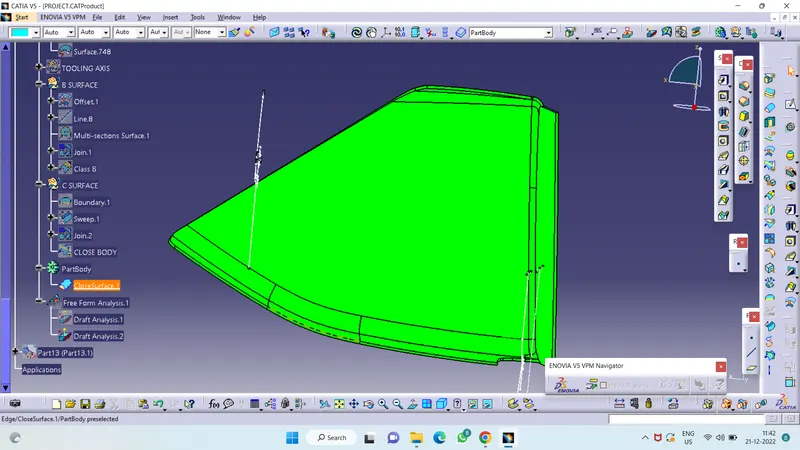
Analysis shows the drafted walls of the base bracket are above 3 degrees which is permissible for manufacturing in injection molding.
4. Inner Map pocket :
Given Class A Surface :
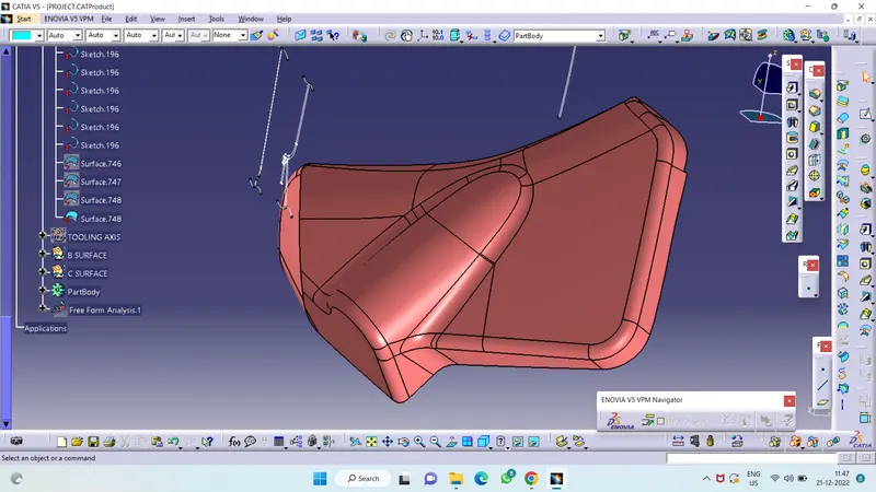
- Class A:
- In automotive design, a class A surface is any of a set of freeform surfaces of high efficiency and quality.
- Class A surfacing is done using computer-aided industrial design applications. Class A surface modellers are also called "digital sculptors" in the industry. Industrial designers develop their design styling through the A-Surface, the physical surface the end-user can feel, touch, see etc.
- A common method of working is to start with a prototype model and produce smooth mathematical Class A surfaces to describe the product's outer body. From this, the production of tools and inspection of finished parts can be carried out. Class A surfacing complements the prototype modelling stage by reducing time and increasing control over design iterations.
- Class A surfaces can be defined as any surface, that has styling intent, that is either seen, touched,
Tooling axis Creation :
In injection molding, the Class A surface is first analyzed to determine the axis or tooling direction that separates the molds. Tooling direction is critical for plastic product design because it determines mold direction.
TOOLING AXIS USING BISECTING METHOD :
Tooling axis for the part is created by using the dummy tooling axis using the bisectiong method .In order to check whether the part is toolable in the direction,the class A surface is analysed and the walls which are doubtful of clearing the 3 degree draft angle to the dummy tooling axis is identified.
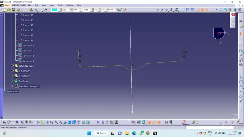
Tree Structure of Tooling Axis :
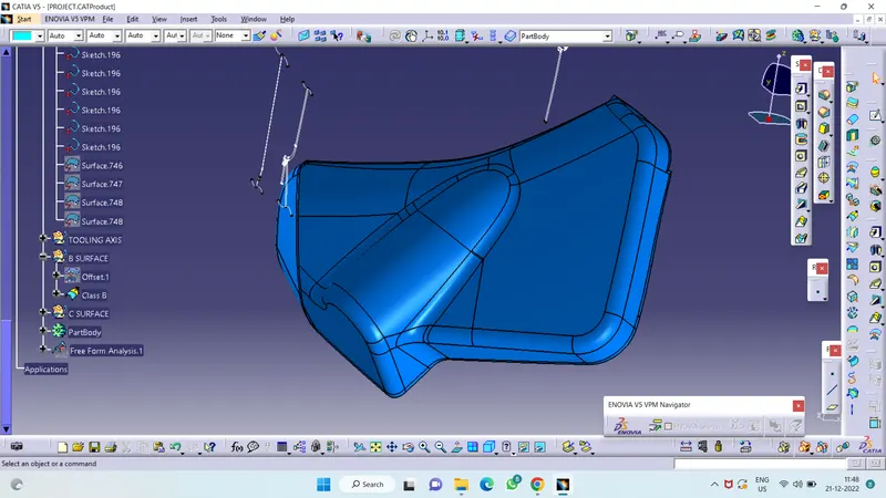
- Class B:
- Class B is the one surface that is mostly used to capture the 2nd half of the part, it is the part that splits into the mould.
- Class B surfaces are the secondary surfaces that you can see sometimes, but are less important, such as the inside of your glove box, ashtray, etc. These must be smooth and "error-free" as well but are not held to the standards that class A surfaces are.
- Class C surfaces:
- These are the backside surfaces that can have tool marks, flash and other imperfections without hurting appearance, function, etc.
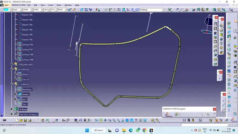
Class (A+B+C) Surface Body :
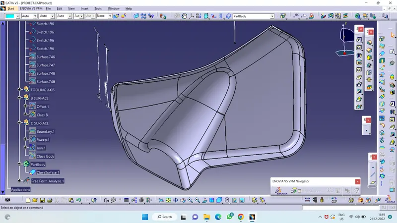
Here we combine all the surfaces into one closed surface using the Trim tool Command.
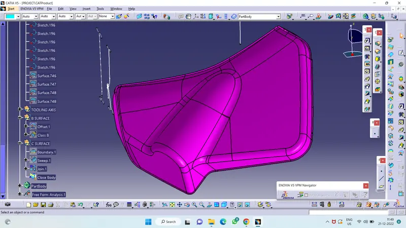
Tree Structure :
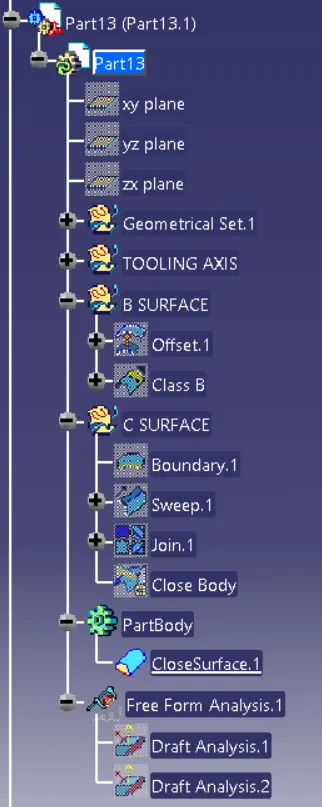
Close Body Surface :
Draft Analysis
For molded or cast parts, the draft angle is the amount of taper perpendicular to the parting line. It is measurable in degrees. Because plastic shrinks and sticks on molding surfaces as it cools, we draft the walls of the plastic part so that it ejects or breaks free from the molding surfaces more easily and without dragging. To reduce the risk of damage to the parts and ensure ejection, a functional injection molding part must have drafts on both the cavity and core sides.
Nominal values for Draft angles
- 3 Degrees is a nominal draft angle
- 5 Degrees can also be manufactured. Increasing the manufacturing cost
- 7 Degrees is considered for Textured surface parts
Importance of Draft in injection molding
- Reduces the possibility of part damage due to friction during the release
- Reduces mold wear and tear
- Ensures a uniform, smooth, unscratched finish
- Ensures the integrity and uniformity of other surface finishes and textures
- Reduces overall cooling time by reducing or eliminating the need for unusual ejection setups
Steps followed for Draft Analysis
- The created part must be changed to the material mode in the display frame
- Compass is enabled and placed in the direction of the Tooling Axis
- The lock command is then used to fix the compass along the tooling axis
- Colour codes are classified and Draft angle is applied
- Running point analysis is used to display permissible draft angle
Draft Analysis of Class A Surface :
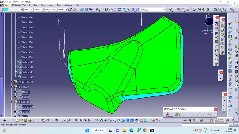
Draft Analysis of Close body Surface :
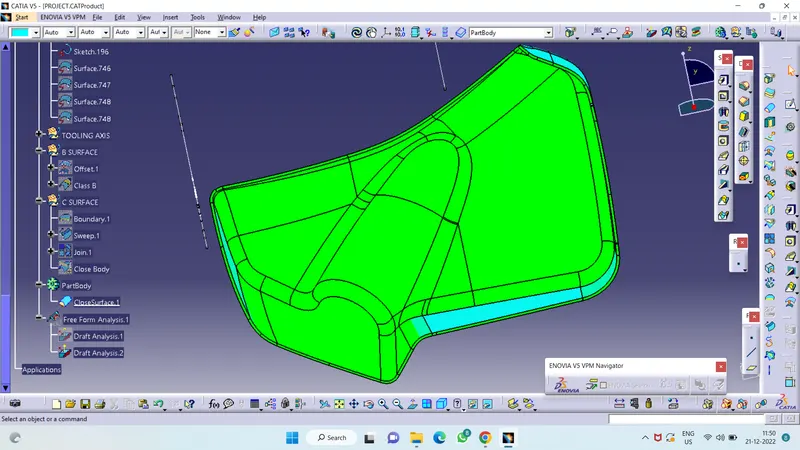
Analysis shows the drafted walls of the base bracket are above 3 degrees which is permissible for manufacturing in injection molding.
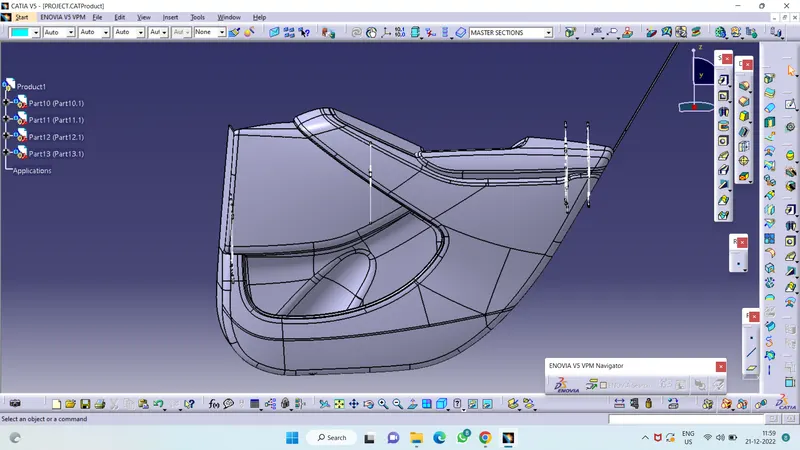
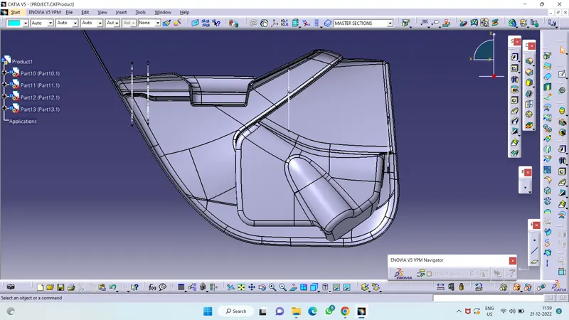
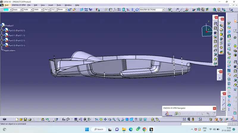
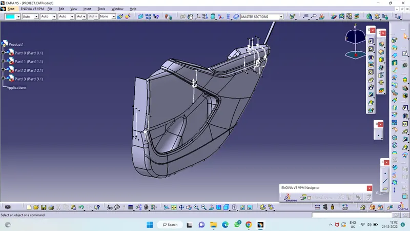
Assembly of Door Trim Pannel :
Engineering Features :
FLANGES:
A flange is a protruded ridge, lip, or rim, either external or internal, that serves to increase strength (as the flange of an iron beam such as an I-Beam or a T-beam); for easy attachment/transfer of contact force with another object.
Below is the Sketch for the two flanges I selected for plastic parts joining with the help of Master sections.
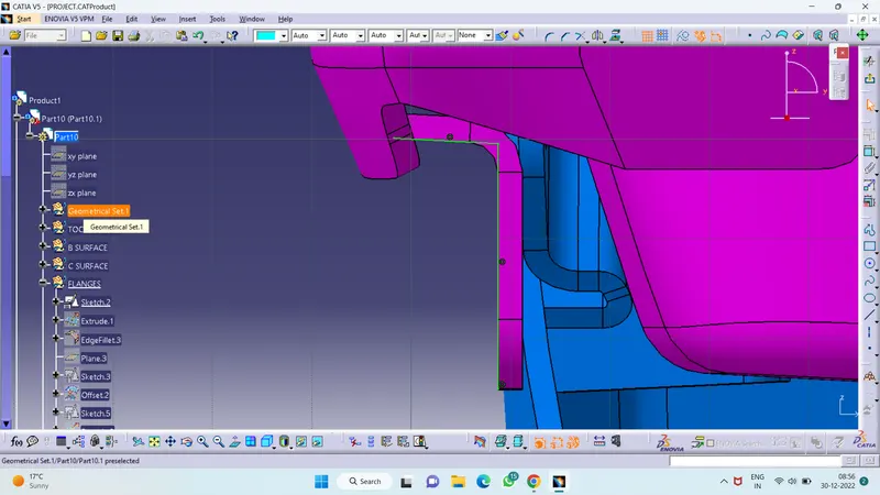
According to the design rule and master, the section provided the flange thickness should be equivalent to the plastic component for rigidity and strength.
A minimum draft of 0.5 degrees and fillets of a minimum of 1 mm is given as per the master section.
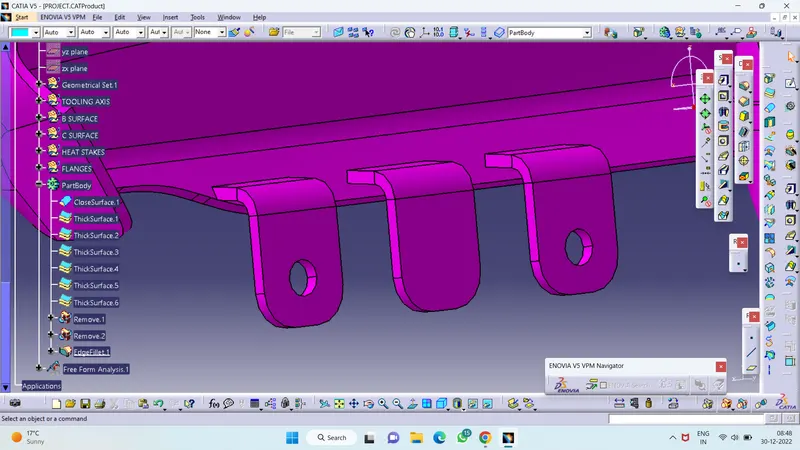
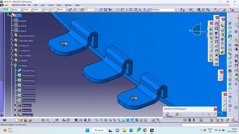
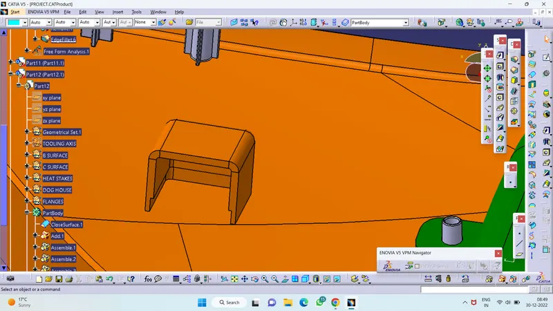
DOG HOUSE :
The dog house is an engineering feature used in the plastic trim design. Dog houses are used as supporting features. Sometimes other engineering features like snaps; locators, etc. are mounded on them to increase their strength.
- Draft 1.5 degree on all walls
- Intersection of part wall Thickness= 0.4* T
- Height =3<->6mm
- Width of dog house =12 mm
- Fillet value 0.25mm
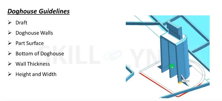
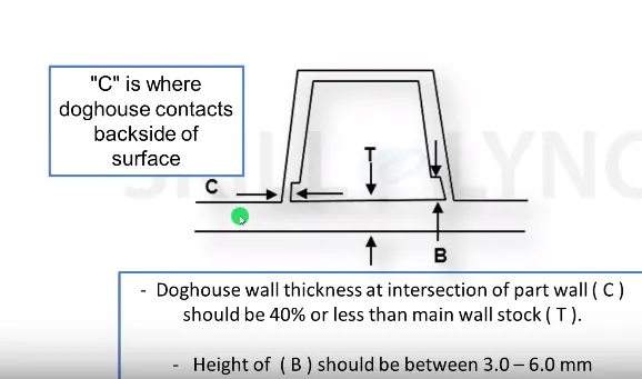
Dog house is an engineering feature used in plastic trim design. Dog houses are used as supporting feature. Sometimes other engineering features like snaps; locators etc. are mounded on them to increase their strength.
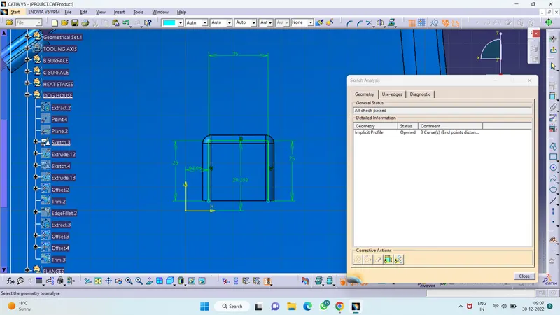
- To create the Dog house, I draw a sketch and padded it to 18mm in height .
- After padding in the direction of tooling axis, I drafted 3deg in the tooling axis direction and filleted it with a 3mm radius.
- Than i remove the material from the base of it having a thickness of 0.4*T=1 mm.
- Than provide draft it to 0.5degree in the direction of side core axis.
- Then shell the main padded structure to 0.7*T=1.75mm.
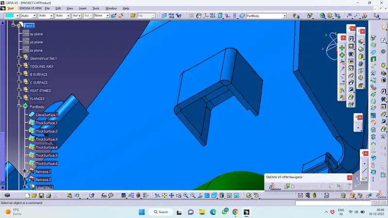
- Remove the second bbody from the first body .
- After joining both the bodies translate it to required points and rotate it with respect to its edge .
- After producing all the dog house unitrim it with the solid surface previously produced.
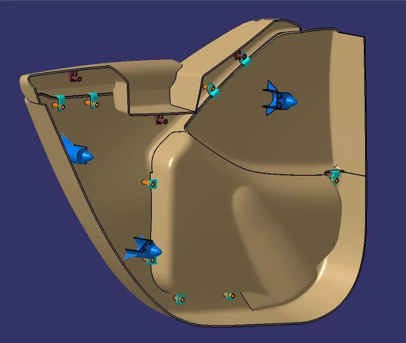
the final produced solid body having all the fetures is shown below...
Sketch :
Locators :
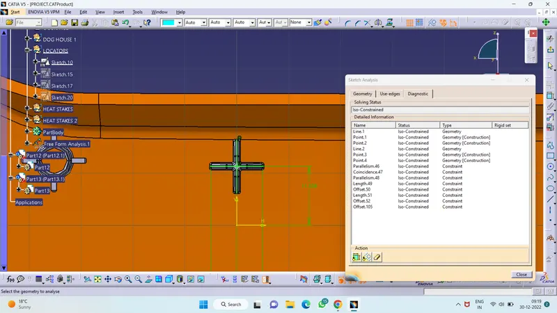
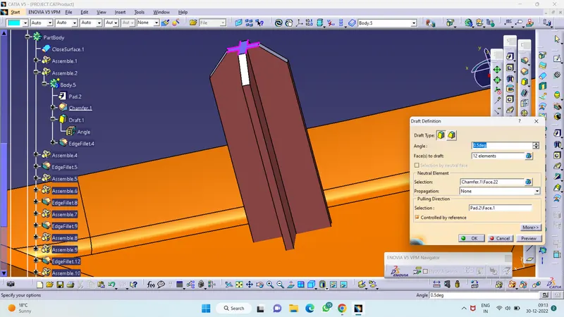
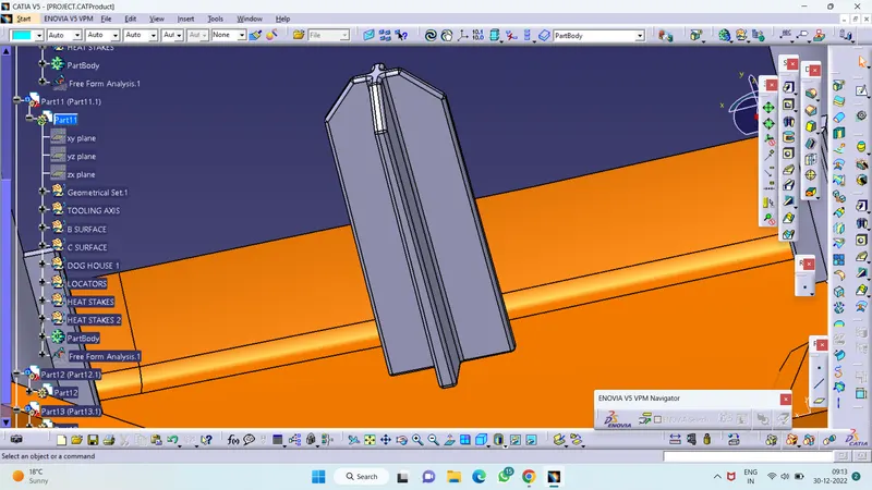
To create the locators,
- I created a sketch on the body.
- After creating the sketch, I pad it 0mm in height and thicken it to 1.3mm and
- I drafted it with 0.5deg in the direction of the tooling axis.
- I gave 3mm of chamfer with 45deg of inclination and after
- I gave a fillet of 0.3mm radius.
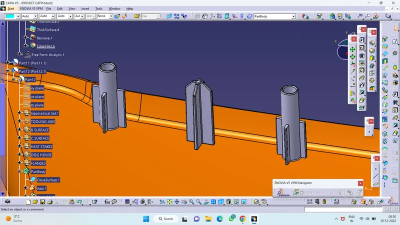
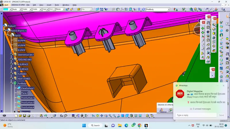
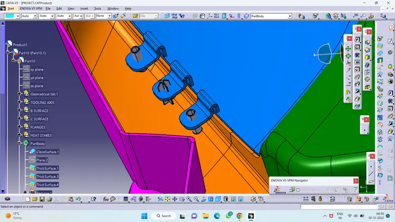
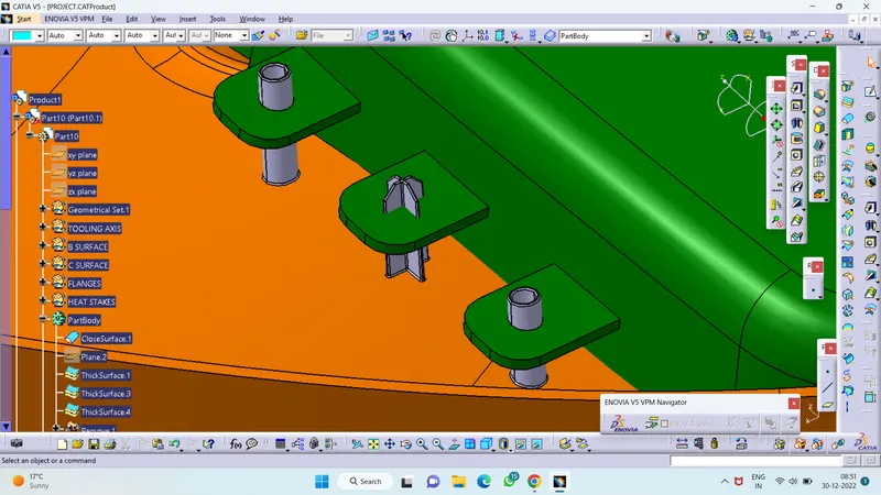
HEAT STAKES:
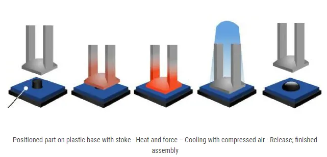
Heat Staking is a pulsed-heat process to join two or more parts out of which one at least is made of plastic. The process is to deform the plastic material using heat and force at a set process time. The bond is made by partially de-forming the plastic part to fix the other.
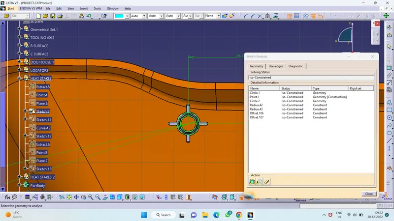
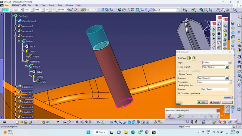
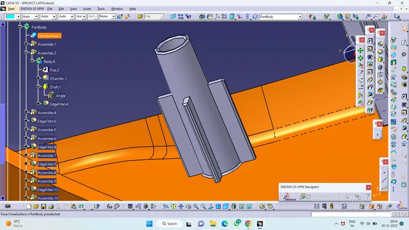
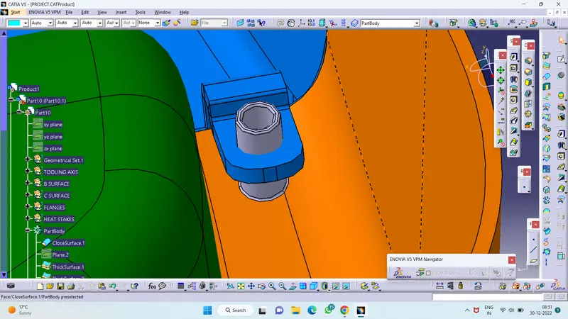
To create the heat stakes, I draw a sketch on the surface. After the creation of the sketch, I pad it to 18mm height and I gave a draft angle of 0.5deg on both sides (inside and outside) and then I gave a fillet with a 0.25mm radius. After creating the heat stake, I created the ribs for supporting purposes. To create the ribs, I draw a sketch and padded it to 12mm in height and 1mm in thickness. After padding the ribs, I drafted 0.5deg in the tooling asix direction and filleted it with a 0.25mm radius. Finally, I union trim the ribs with a heat stake to remove the ribs, which are present inside the heat stakes.
Sketch :
Draft :
Heat Stakes and Locator with Flanges :
3-2-1 Principle:
To locate a part to be machined and restrict its motion to accurately do the machining and constraint its motion 3-2-1 principle of location is used.
To completely specify the position in space of a three-dimensional
object (such as the cube that’s shown), we refer to six coordinates:
- Translational position along the X-axis
- Translational position along the Y-axis
- Translational position along the Z-axis
- Rotational position about the X-axis
- Rotational position about the Y-axis
- Rotational position about the Z-axis
It is a 3 step process of introducing 3-2-1 point locators in a plane for best support and constraint.
For example, let's say we use 3 points at the bottom of the cube above, which restricts the translational motion along Z(Z+ and Z-), Rotational motion along Y and X(7, 8, 9, 10) This way three degrees of motions have been restricted.
Now we use 2 points from the Y+ direction of the cube to restricts the Translational motion along with Y(Y+ and Y-), Rotational motion along with Z. This way two degrees of motion are restricted.
Finally to restrict motion along the only remaining degree of freedom that is the Translational motion along the X(X+ and X-) a single point is used along the X+ direction of the cube to restrict all the motion.
According to the above principle and using it as the base for creating points for perfectly restricting any movements of parts in the body when attached to the main door panel, I placed required flanges and heat stakes along the body.
For attaching the flanges to the body, I used the add command with translation and rotation command to fix the two parts.
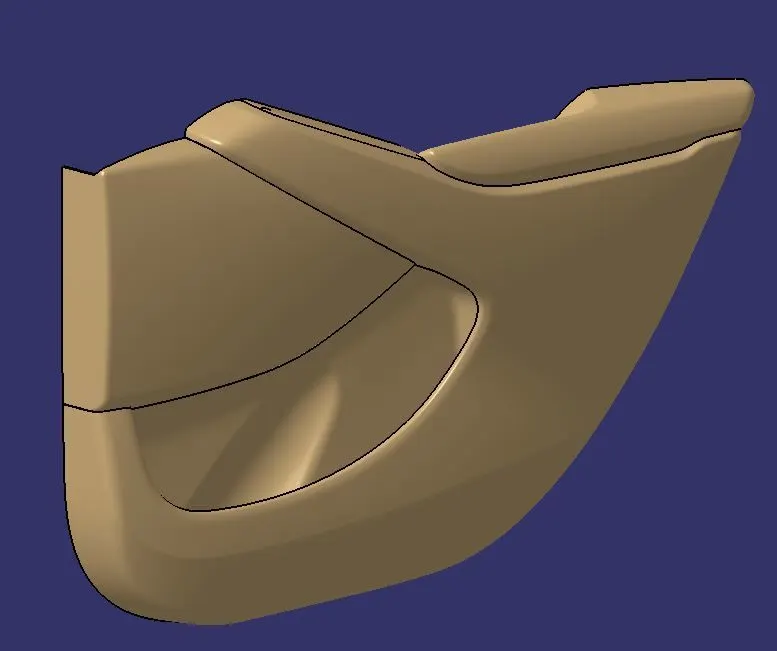
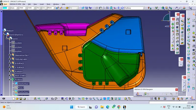
Final Door Trim Pannel :
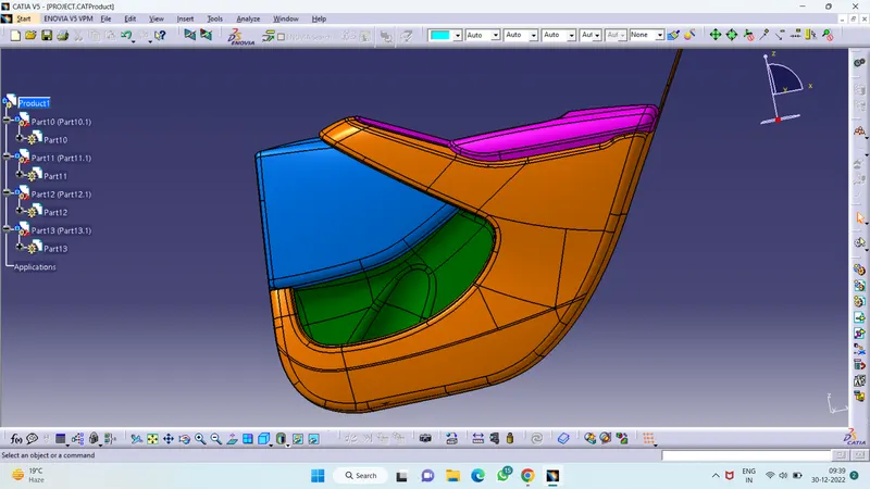
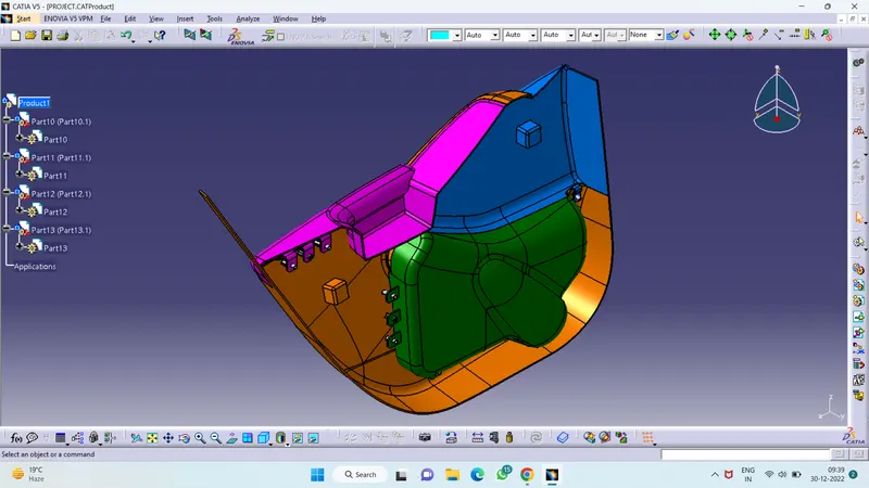
Isometric View :
CONCLUSION:
The door trim panel was successfully created with all the design rules taken into considerations for feature attachment and the main part was created using the master section provided with the input class A.