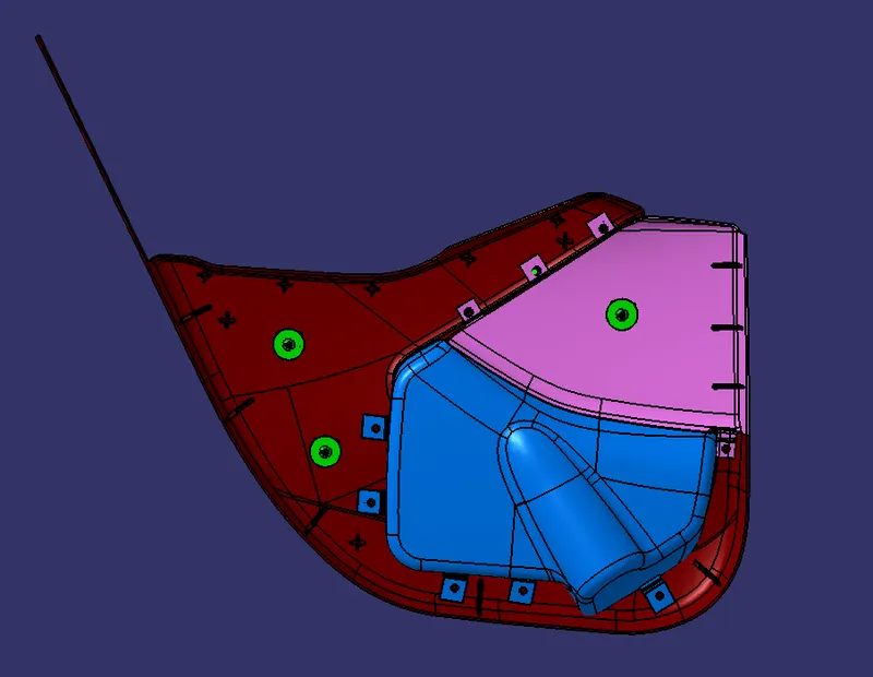
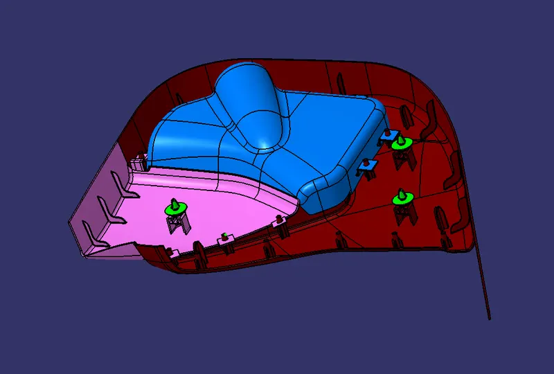
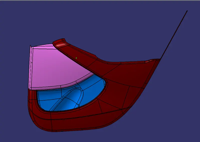
Week 11 - Final project
FINAL PROJECT
AUTOMOTIVE PLASTIC DESIGNING
AIM : To design a Door Trim Panel of an Automotive using catia V5
OBJECTIVE : To create the part body for all given Class-A surfaces as per given master section and perform the draft analysis for given Class-A surfaces as well as for close surface of each part. To create the B-side attachmant feature as per requirement and assemble the push-pin/clip with the dog house.
PROCEDURE :
VERIFICATION OF CLASS-A SURFACE :
Class-A surface of different parts of door panel received from the styling team as an input. Class-A
surface is the first input given to the plastic designer. At first we have verify the Class-A surface and find out that is there any defect in the given Class-A surface or not . We have check the draft analysis of Class-A surface, Gap and Flush between surface, opening in surfaces, twist in surface , intersection between the Class- A surfaces of different parts etc.
ARM REST :
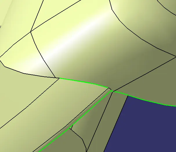
(1) There is an opening in the given Class-A surface of Arm Rest. For that at first we have to discuss with the Styling Engineer after discussion we can close the surface with maintaining the quality of Class-A surfece.
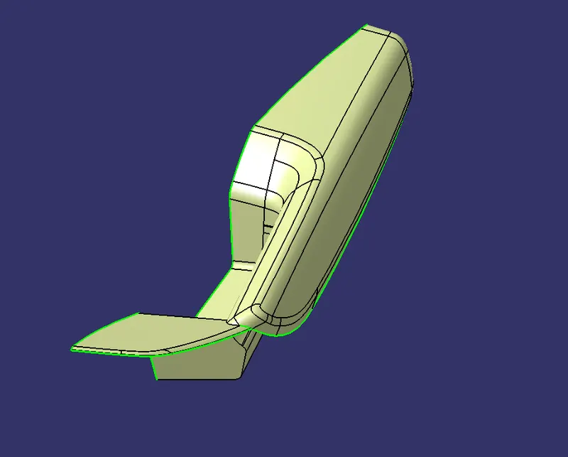
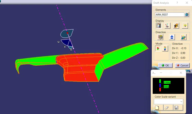
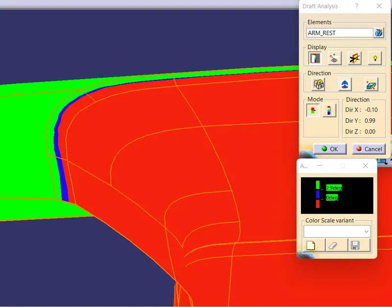
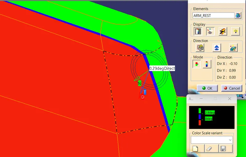
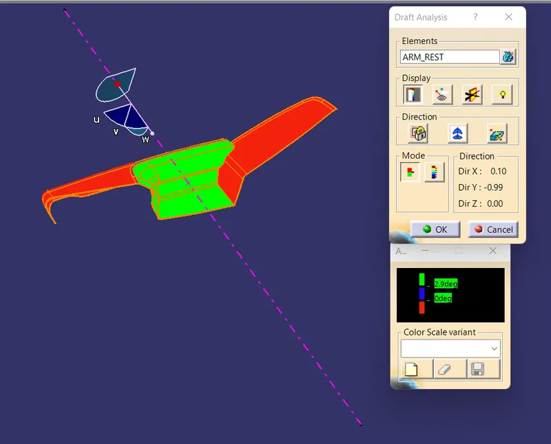
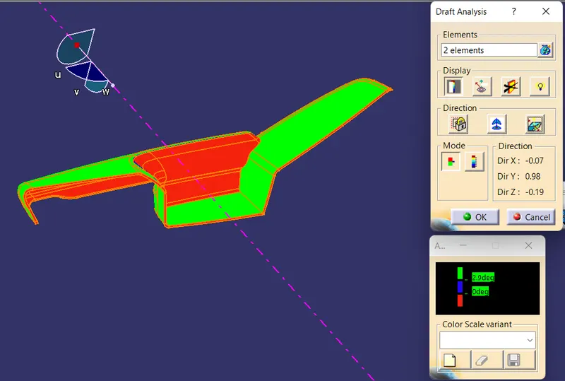
(2) : In the some portion of Class-A surface of Arm Rest the draft analysis is not correct in 3 degree draft. We tried various method and various direction for creation of main tooling axis but draft analysis is not correct completely in any of the direction, Finally created tooling direction is that direction in which most of the portion of Class-A surface in OK in draft anlysis . For that we can contact to Styling Engineer and final the tooling direction as per discussion.
BOTTLE HOLDER :
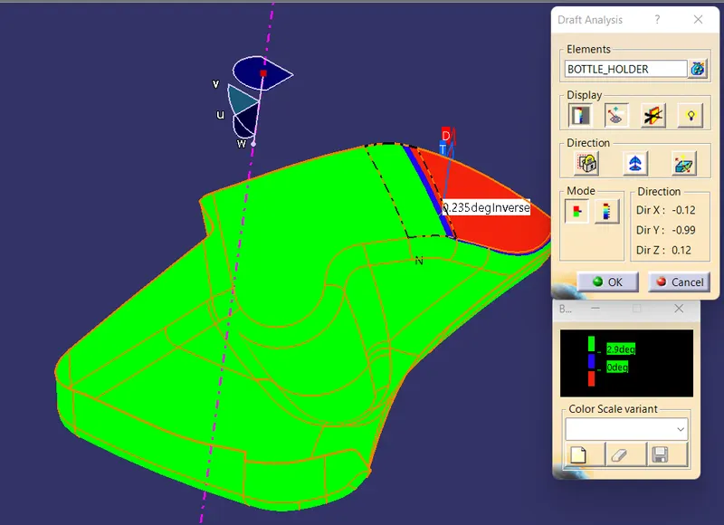
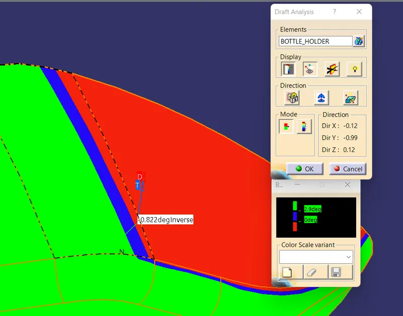
(1) In some portion of Class-A surface of bottle holder the draft analysis is not correct while performing the draft analysis in 3 degree. We tried to create the main tooling axis by different method and in different direction but draft analysis is not complete correct in any of the direction . In above created tooling direction the draft analysis is correct for most of the portion of Class-A surface.For that we can discuss with styling engineer and final the tooling direction as per discussion.
CREATION OF VARIOUS PARTS AND B-SIDE ATTACHMENT FEATURE :
In the door panel given Class-A surface has the following parts -
1) Door Arm Rest
2) Lower substrate
3) Map pocket
4) Bottle Holder
1) DOOR ARM REST :
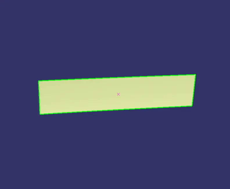
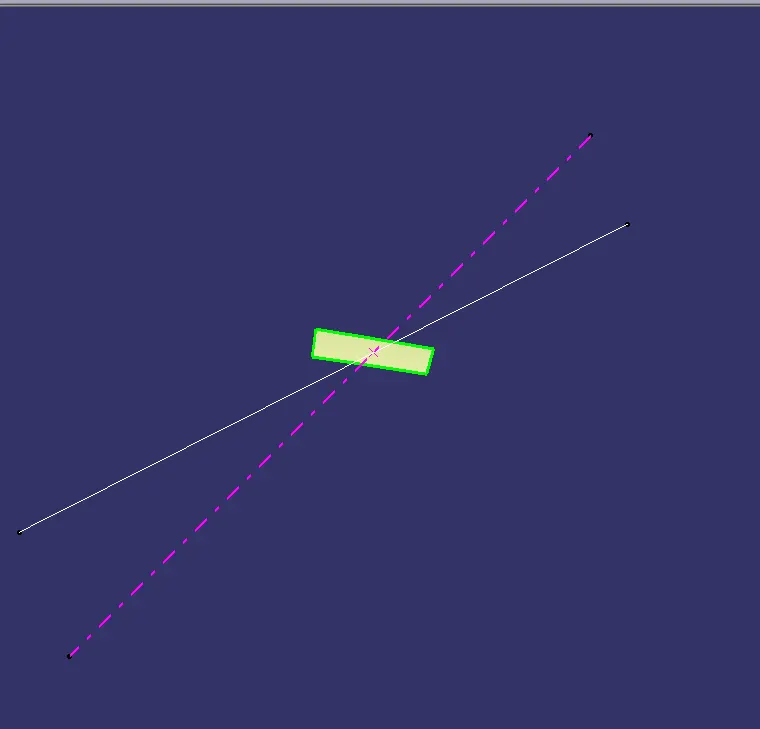
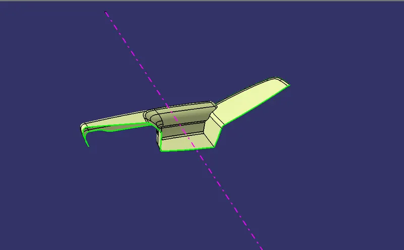
CREATION OF TOOLING AXIS : POINT AND DIRECTION METHOD
Extract a surface from class-A surface
Create a point on it
Create a line from that point in appropriate tooling direction
If draft analysis is not correct with respect to that line then we can check by rotating that line by small value .
DRAFT ANALYSIS OF CLASS -A SURFACE :
- Change View mode customization to material mode .
- ANALYSIS : FEATURE : FEATURE DRAFT NANALYSIS and move the compass to the main tooling axis.
- Set the value of angle and colour code for draft analysis .
- Now we can perform the draft analysis in various mode such as Quick Analysis Mode , Full Analysis Mode and Analysis under running point.
CREATION OF CLASS -B SURFACE :
Class-B surface is created by following the master section . We can measure the thickness of part from given master section and offset the class-A surface at that distance. If in any portion surface is not offseting then we can use various commond /tool for that with maintaing the uniform wall thickness.
CREATION OF CLASS -C SURFACE : We can create the Class-C surface by sweep the extracted boundray of class-A surface with draft direction ,or sweep with reference surface and by using multisection commond as per required.
CREATION OF CLOSE SURFACE AND PART BODY :
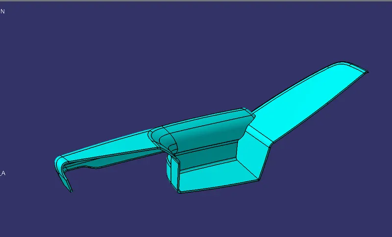
After creating the class-C surface we have join the Class-A and Class-C surfaces and trim them by Class-B surface. We get a close surface as a result. Now by using close surface commond we can create a close body.
ARM REST PART BODY
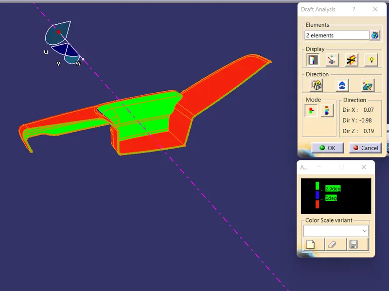
DRAFT ANALYSIS OF CLOSE SURFACE :
After creating the close surface we have perform the draft analysis for close surface. Also for close surface the minimum draft angle value is 3 degree .
(2) DOOR LOWER SUBSTRATE :
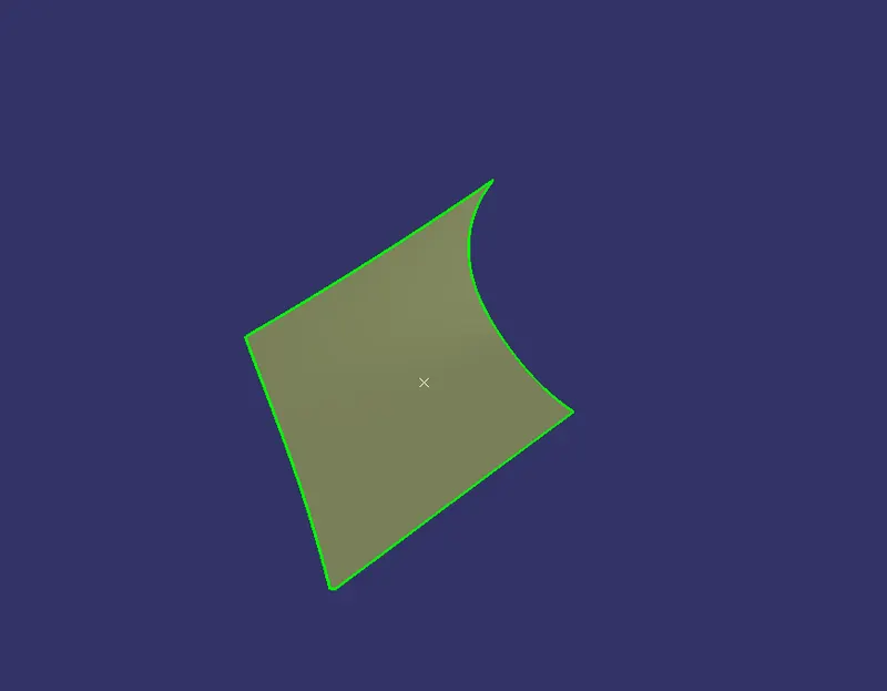
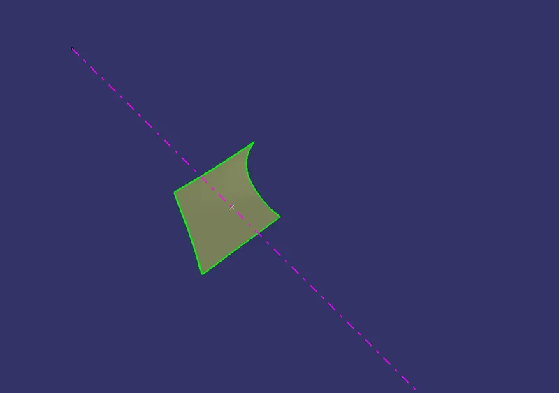
CREATION OF MAIN TOOLING AXIS : POINT AND DIRECTION METHOD
Extract a surface from class-A surface
Create a point on it
Create a line from that point in appropriate tooling direction
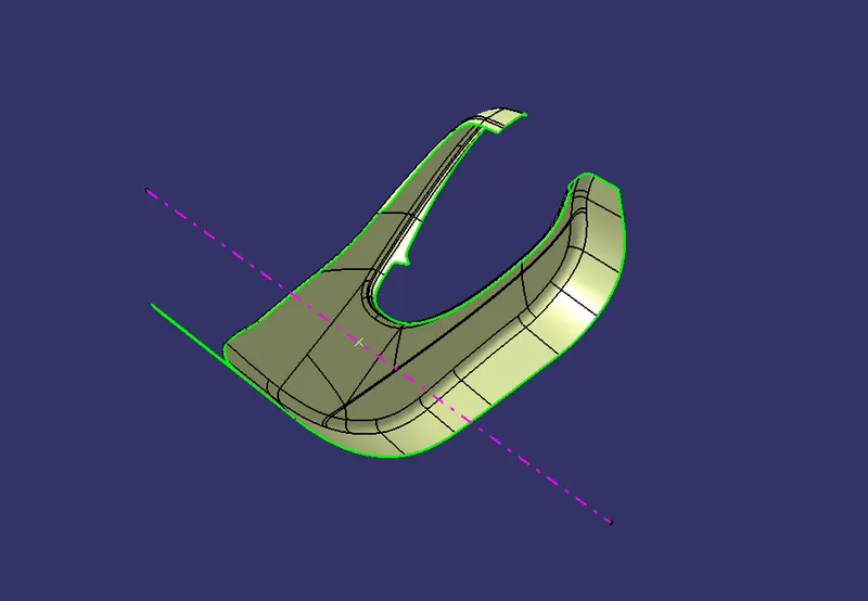
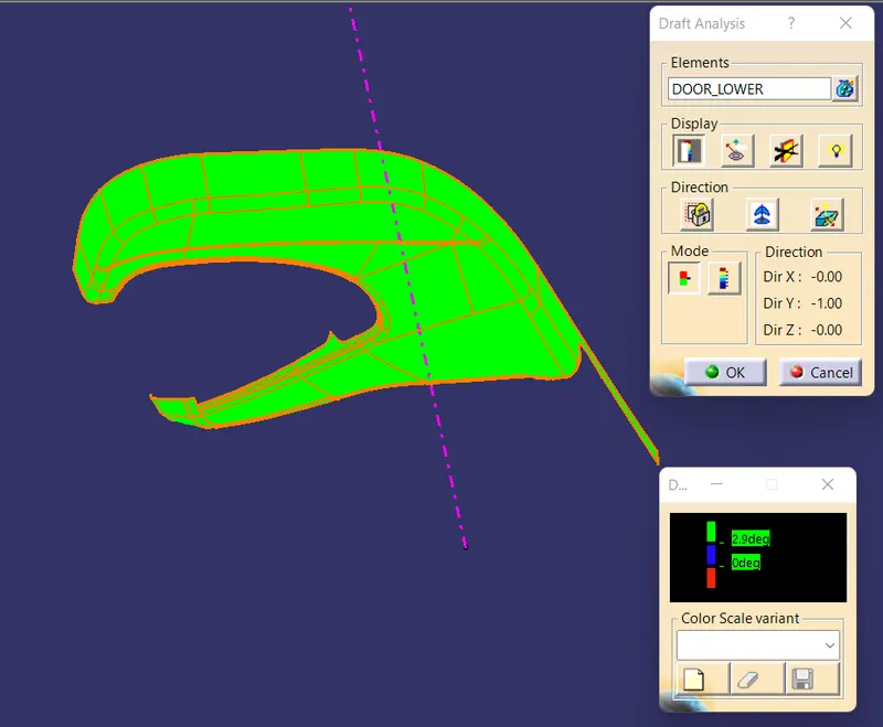
DRAFT ANALYSIS OF CLASS-A SURFACE :
PROCEDURE : As above
DRAFT ANGLE : Minimum 3 degree
CREATION OF CLASS -B SURFACE , CLASS-C SURFACE AND CLOSE SURFACE :
PROCEDURE : AS ABOVE
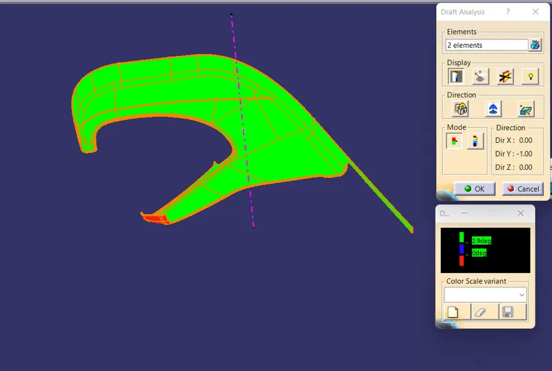
DRAFT ANALYSIS OF CLOSE SURFACE :
PROCEDURE : As above
DRAFT ANGLE : Minimum 3 degree
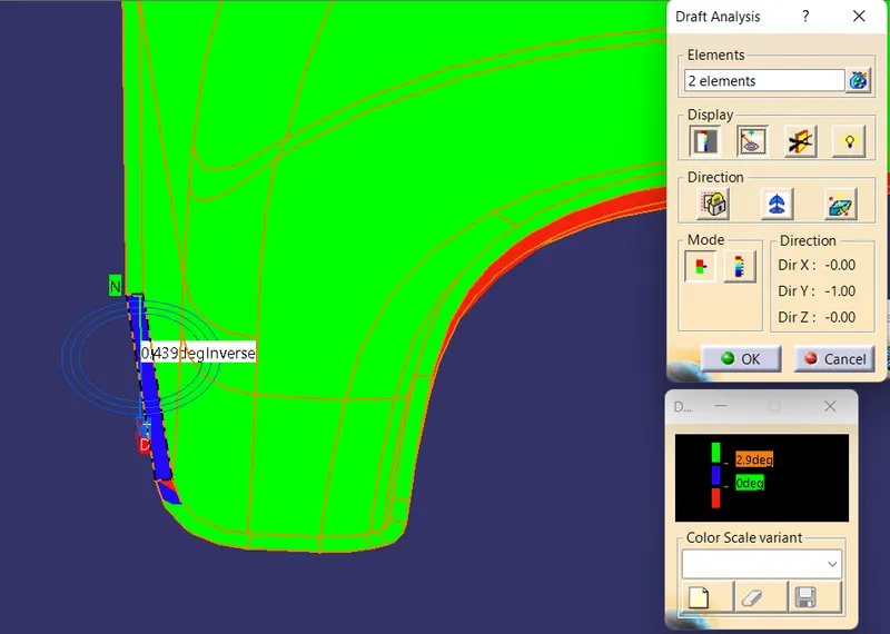
In door lower substrate for a small portion of class-C surface the draft analysis is not correct for the draft angle of 3 degree . Here the minimum draft angle is almost 0.4 degree .( as discussed in common support session it is acceptable for small portion )
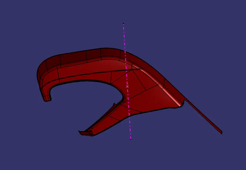
CREATION OF PART BODY :
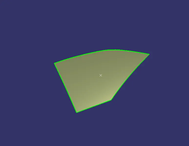
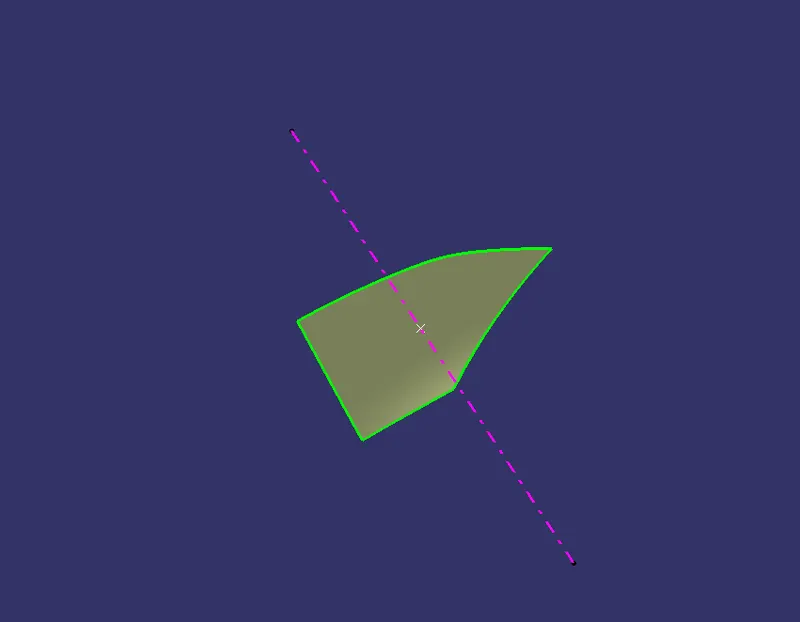
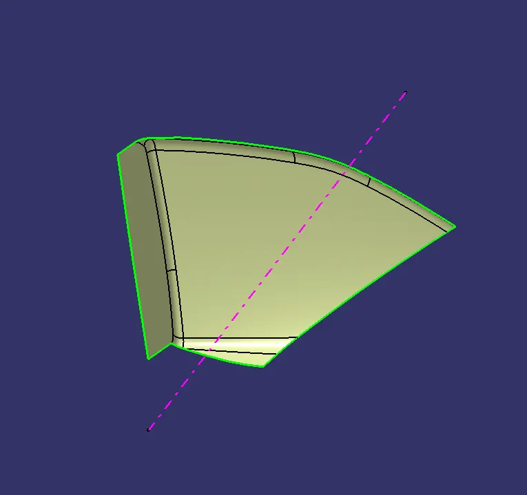
(3) MAP POCKET :
CREATION OF MAIN TOOLING AXIS : POINT AND DIRECTION METHOD
Extract a surface from class-A surface
Create a point on it
Create a line from that point in appropriate tooling direction
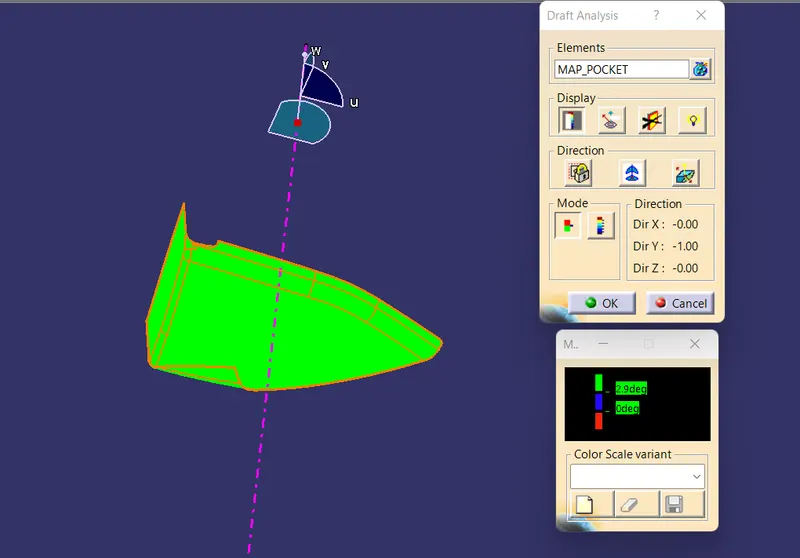
DRAFT ANALYSIS OF CLASS-A SURFACE :
PROCEDURE : As above
Draft Angle : Minimum 3 degree
CREATION OF CLASS -B, CLASS-C, AND CLOSE SURFACE :
PROCEDURE : As above
DRAFT ANALYSIS OF CLOSE SURFACE :
PROCEDURE : As above
Draft angle : Minimum 3 degree
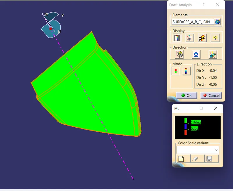
CREATION OF PART BODY :
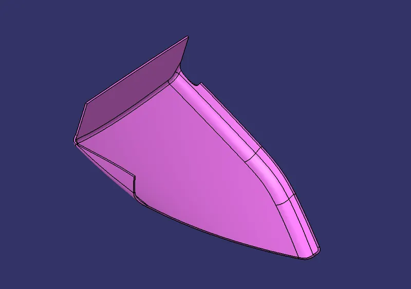
(4) BOTTLE HOLDER :
CREATION OF MAIN TOOLING AXIS : POINT AND DIRECTION METHOD
Extract a surface from class-A surface
Create a point on it
Create a line from that point in appropriate tooling direction
If draft analysis is not correct with respect to that line then we can check by rotating that line by small value .
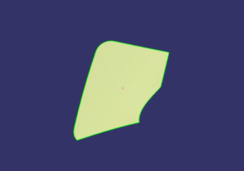
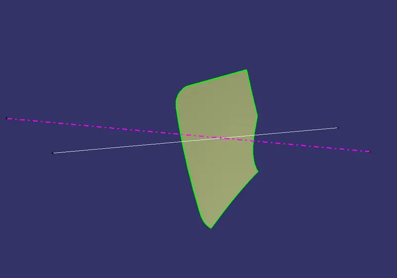
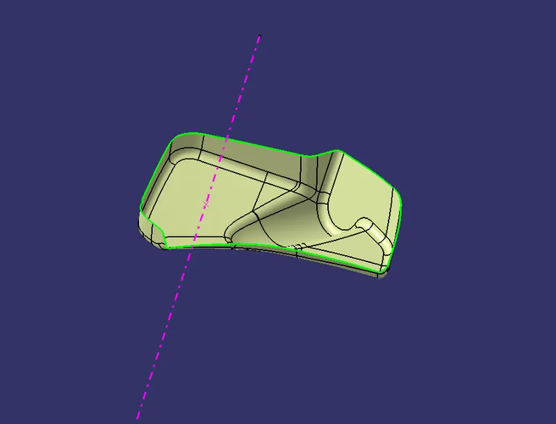
DRAFT ANALYSIS OF CLASS-A SURFACE :
PROCEDURE : As above
DRAFT ANGLE : Minimum 3 degree
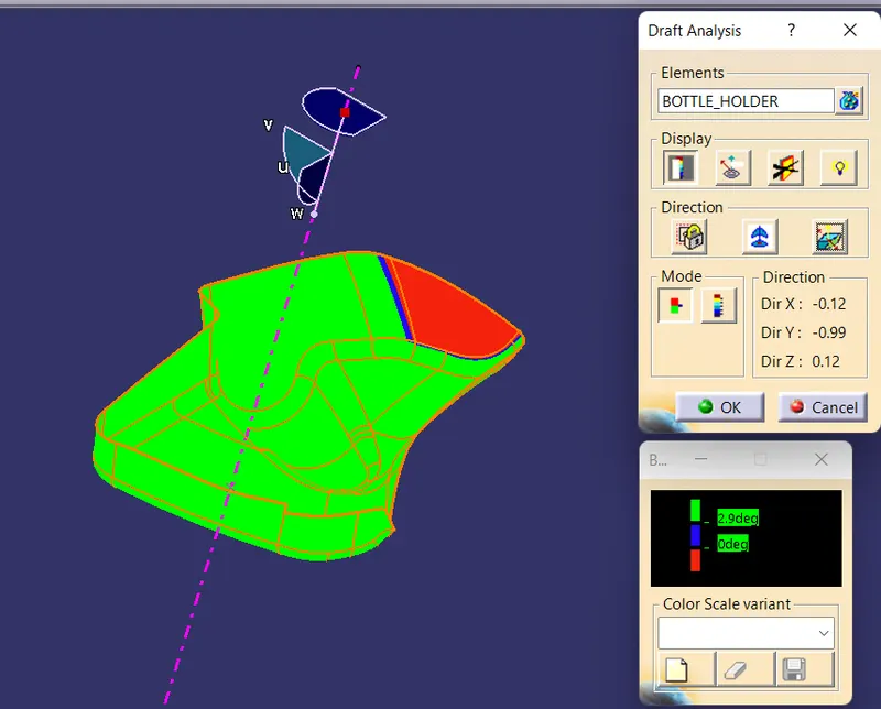
CREATION OF CLASS-B, CLASS-C AND CLOSE SURFACE :
PROCEDURE : As Above
DRAFT ANALYSIS FOR CLOSE SURFACE :
PROCEDURE : As Above
DRAFT ANGLE : Minimum 3 degree
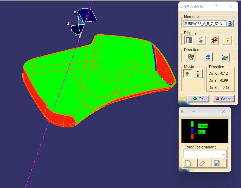
CREATION OF PART BODY :
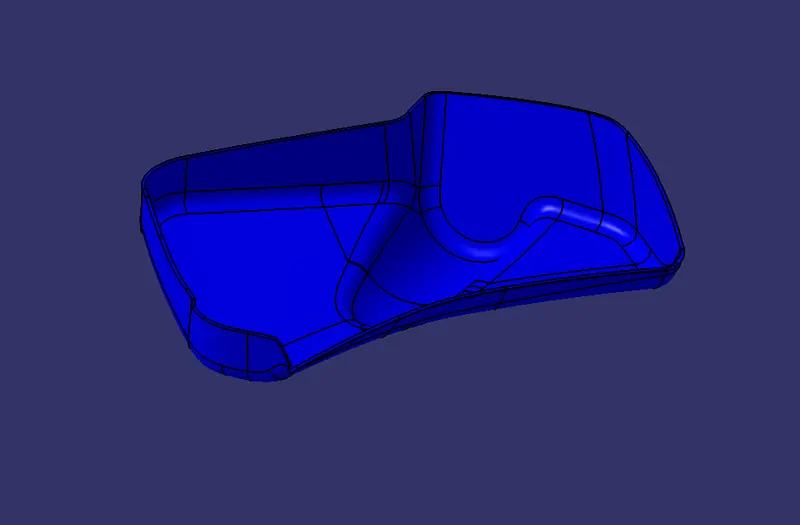
B-SIDE ATTACHMENT FEATURE :
In the door panel trim we used the following attachment feature
1) DOG HOUSE
2) LOCATOR
3) HEAT STAKE
4) FLANGES
5) RIBS
6) PUSH-PIN/CLIP
DOG HOUSE :
For the design of dog house we used the following drawing
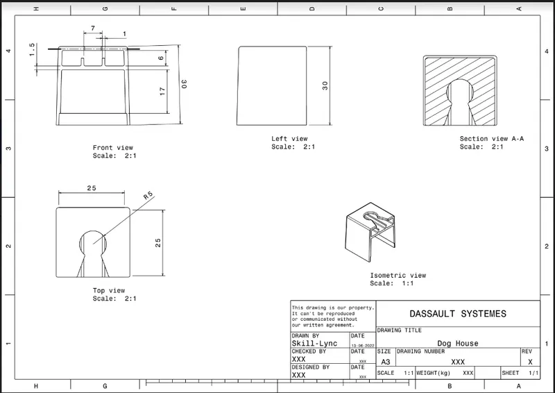
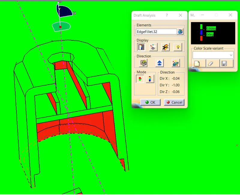
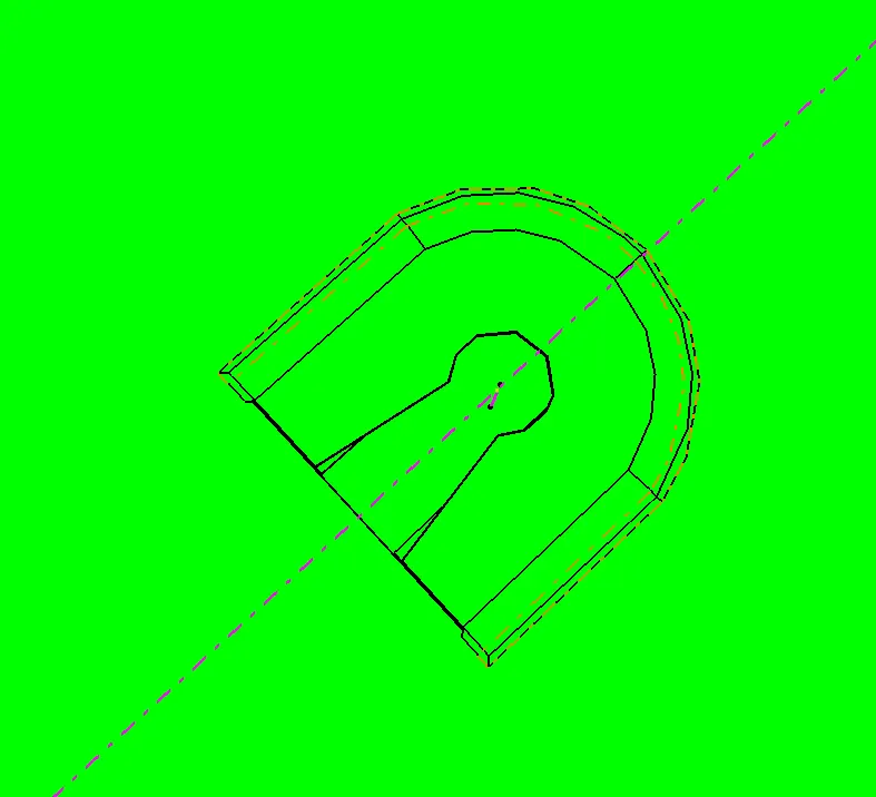
DRAFT ANALYSIS : For the Dog House we have perform the draft analysis two times
In main tooling direction : Minimum Draft angle is 1 degree
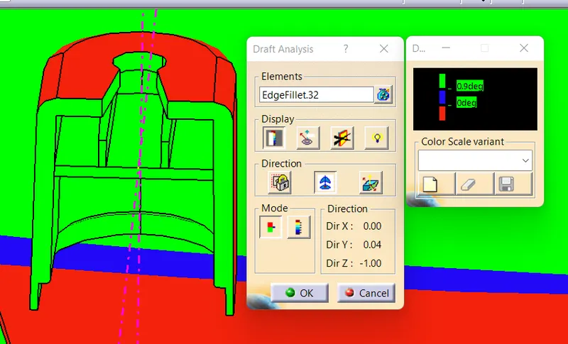
IN LIFTER DIRECTION : Minimum draft angle is 1 degree
LOCATOR, HEATE STAKE AND FLANGES :
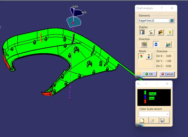
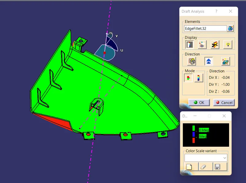
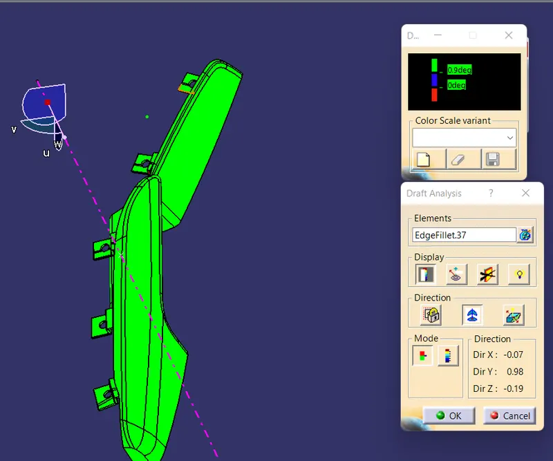
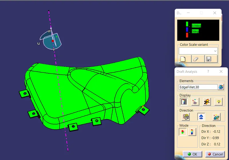
Locator, heate stake,Ribs and flanges will clear in main tooling direction .Minimum draft angle provided for these features is 1 degree .
DRAFT ANALYSIS OF DOOR LOWER SUBSTRATE WITH FEATURES :
DRAFT ANALYSIS OF MAP POCKET WITH FEATURES :
DRAFT ANALYSIS OF ARM REST WITH FEATURE :
DRAFT ANALYSIS OF BOTTLE HOLDER WITH FEATURES :
ASSEMBLY OF ALL PARTS : BOTTOM-UP ASSEMBLY APPROACH
After creating all the part bodies and required B-side attachment feature we go to the assembly workbench and insert all part file existing component . After That required number of copies of push-pin/clip file inserted into the assembly workbench and required constrained is provided between the dog house and the push pin clip. Now our product file of door trim panel is ready.