Week 11 - Final project
Development of a Door Trim panel
Objective:
- a) Creation of side door trim panle from given class A surface. Apply thickness to it and use attachment features.
- b) Creation of flanges and heat stakes from given master sections.
- c) Creation of dog house and various attachment features using industry standards.
- d) Performing draft analysis and ensuring the features and surfaces clear it.
There is ten stages in automotive product life cycle developement. In this case our project is step 5 & step 6, that is New Product design and development. The objective is to design class B and class C surface from given class A surface and create a solid body from it using softwares like CATIA V5 taking into consideration the draft analysis which makes the component suitable for production using injection molding process.
Steps:
Given below is the procedure to create a new plastic component from given class A surface .
1) Creation of tooling axis
2) Creation of class b surface
3) Creation of class C surface
4) Creation of closed body
5) Draft Analysis .
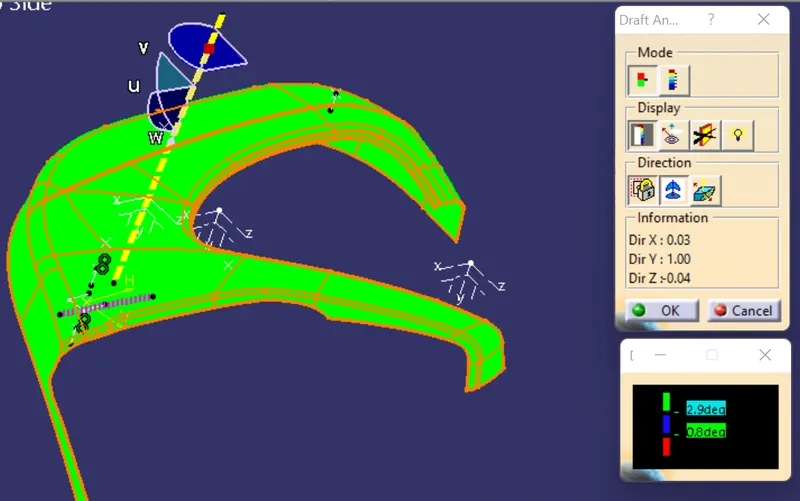
Draft analysis is done to ensure that the designed part is manufacturable based on the draft conditions applied. It is done to ensure the proper ejection of the component from dies(for metals) or molds(for plastics). The basic idea is to ensure that the tooling axis has to be created in such a wat that it has no parallel surface profiles of the component so that the ejection of the components can be ensured . Tooling axis is the axis along which cavity and core are closed and opened .
The main components of interior door panel of a car consists of the following parts .
1) Arm rest
2) Map pocket (Consists of upper and lower part)
3) Upper substrate (Not given in the current model)
4) Lower substrate .
Creation of tooling axis :-
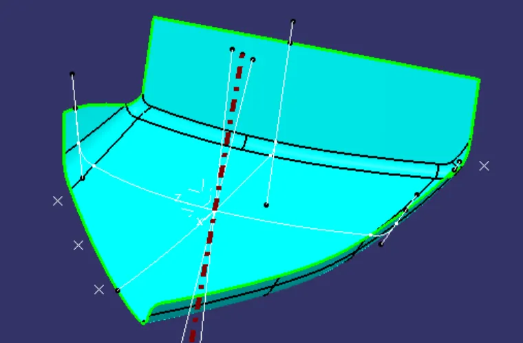
Armrest-
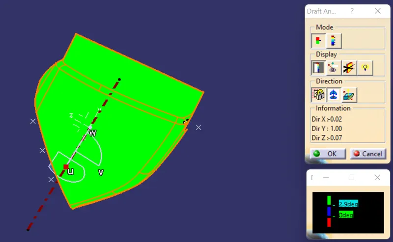
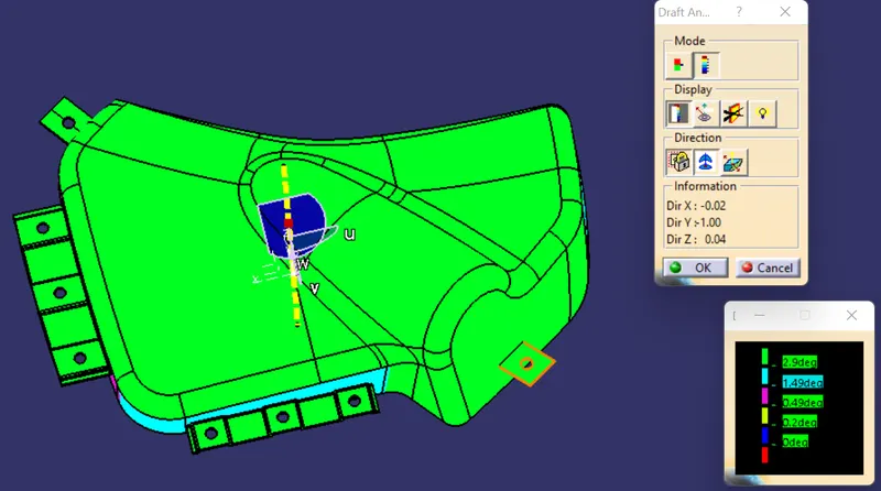
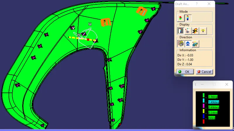
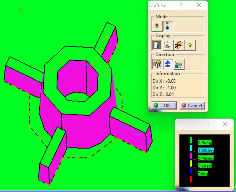
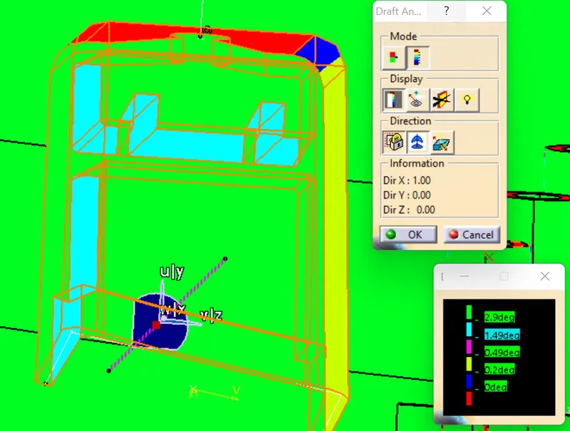
Designers of plastic parts and mould tooling manufacturers can use the Draft Analysis tool to check the correct application of draft to the faces of their part. With draft analysis, you can verify draft angles, examine angle changes within a face, as well as locate parting lines, injection, and ejection surfaces in parts.
For this case as no hole is concerned, so we will try to consider the perpendicular axis of that dented curved surface, for creating the tooling axis. So we will analyse perpendicular plane.
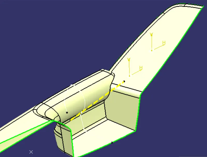
Class A Draft Analysis-
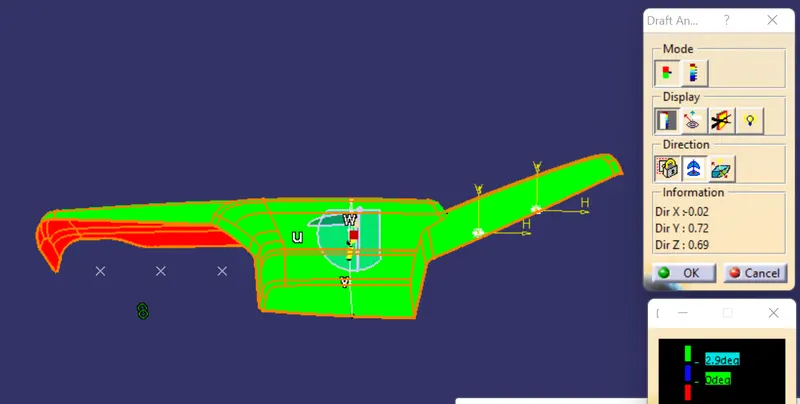
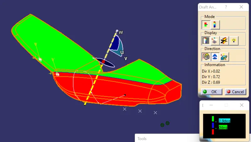
As we can see from the image that except back side, all parts are clearing draft analysis. So for that back part, we can make a seperate part or we can use a side core. Here we have created a side core and with that side core axis back side are cleared draft analysis.
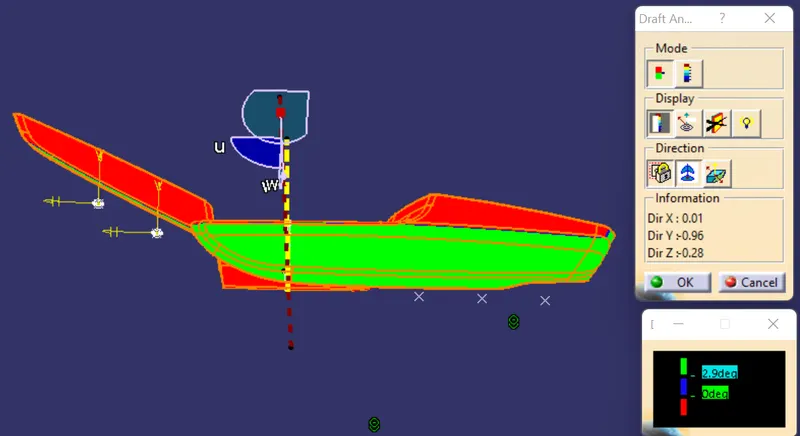
Upper Map Pocket -
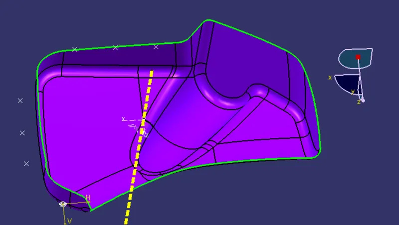
Using same method we will create tooling axis for rest of the parts.
Draft Analysis-
Lower Map Pocket -
Draft Analysis-
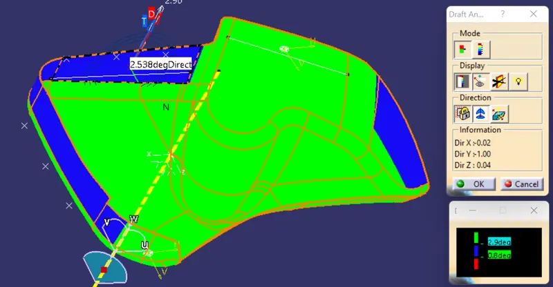
In this case we can see that yhe blue zones are not clearing draft angle. Minimum draft angle is 2.5 degree, that is not acceptable. So we have to inform Class-A surface making team.
Lower Substrait -
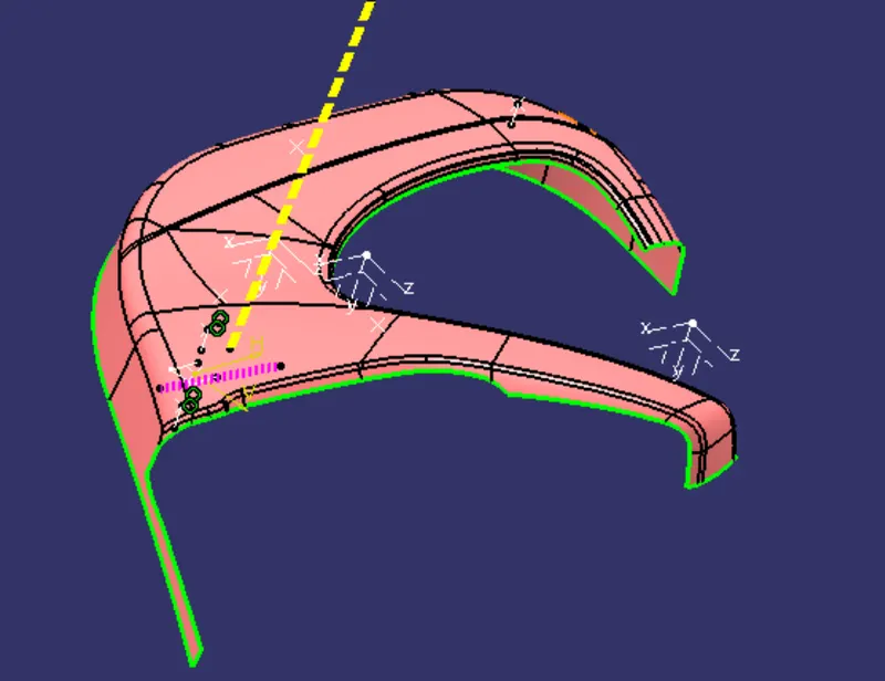
Draft Analysis-
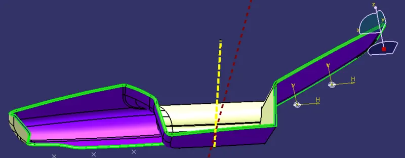
Creation of class B surface :-
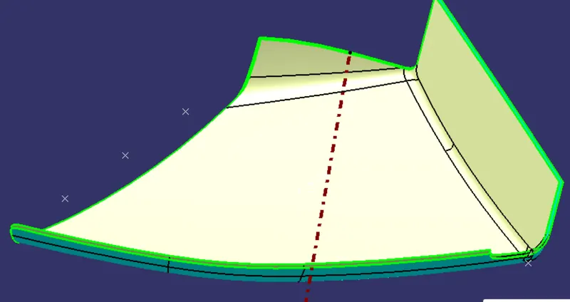
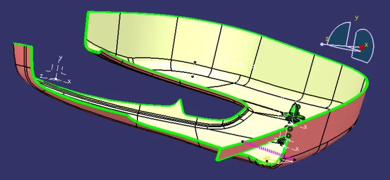
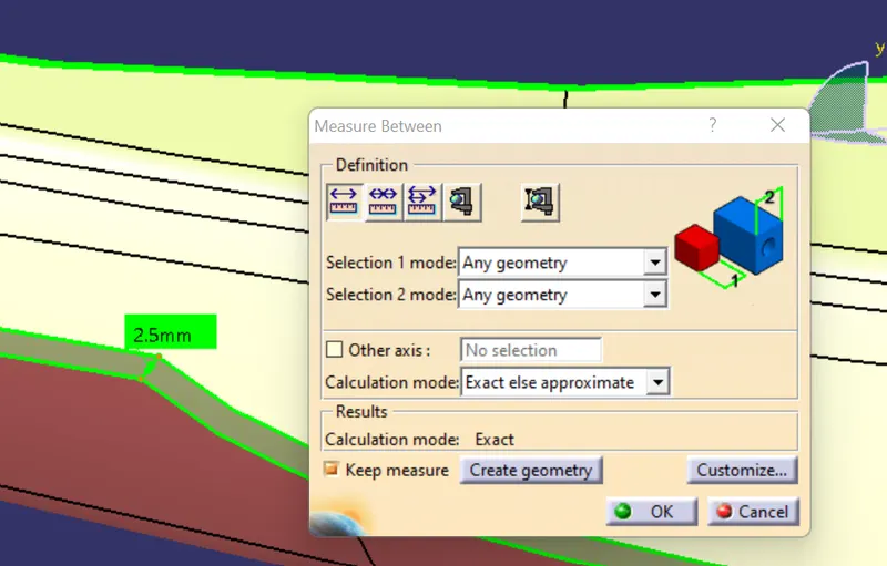
To create class B surface use offset tool with a distance value of 2.5mm to create offset of class A surface. After offsetting , extrapolate tool was used to extend all the edges of this surface . This is done to ensure that the parting line comes at B surface. In areas where extrapolate was not possible (Fillet or cusped surfaces) multisection surface option was used. Join all the extrapolated surface and multi section surfaces to obtain a single surface. Hence the class B surface was created for all parts.
Class B for Armrest-
Class B for upper map-pocket-
Class B for lower map-pocket-
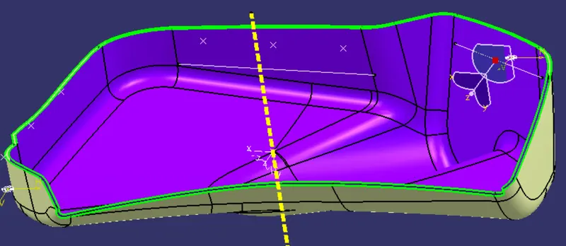
Class B for lower substrait-
Creation of Class C surface :-
To make class C surface use sweep command to create a new surface an an angle with respect to a surface. This angle is dependant on draft angle for free edges and ususally 90 degree for mating surfaces. In areas where sweep is not possible , use Multi section surface to create a new surface. Join all surfaces to obtain C surface. In this wat class C surfaces were obtained for all other components.
Class c for armrest-
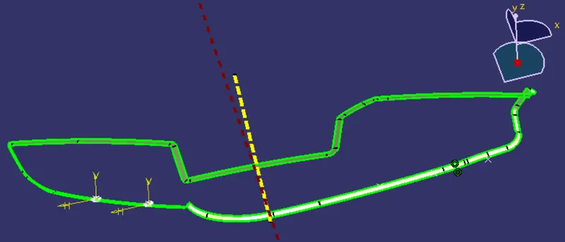
Class c for upper map-pocket-
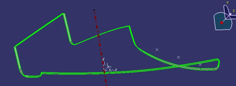
Class C for lower map-pocket-
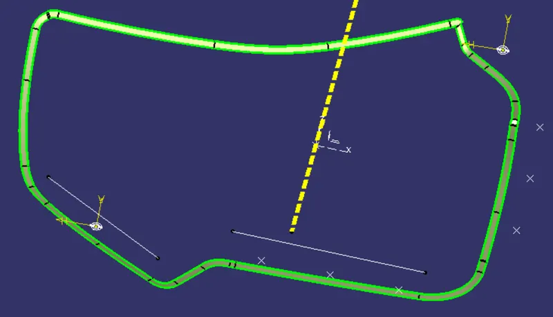
Class C for lower substrait-
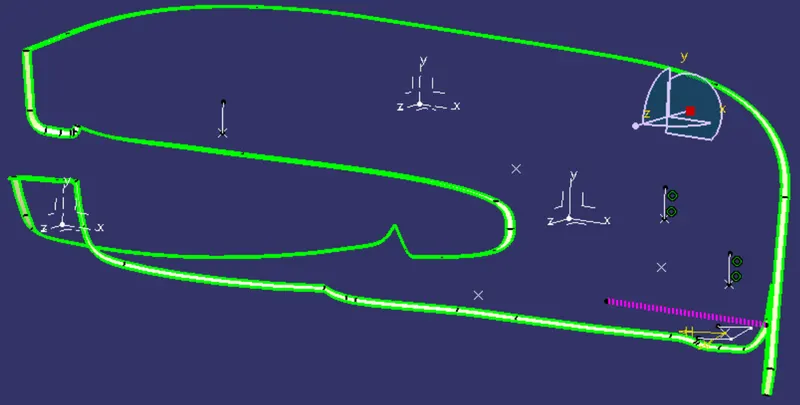
Creation of closed surface :-
Use trim or join option to join Class A and Class C. Use trim option to join above trim with class B. Similarly closed body was obtained for all other parts.
Closed surface for armrest-
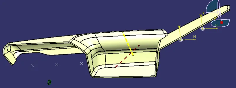
closed surface for upper map-pocket-
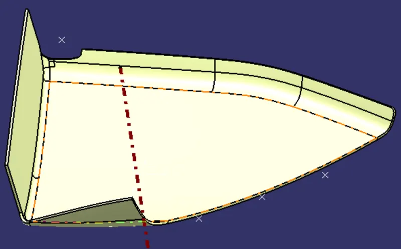
closed surface for lower map-pocket-
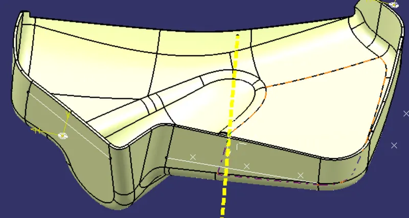
closed surface for lower substrait-
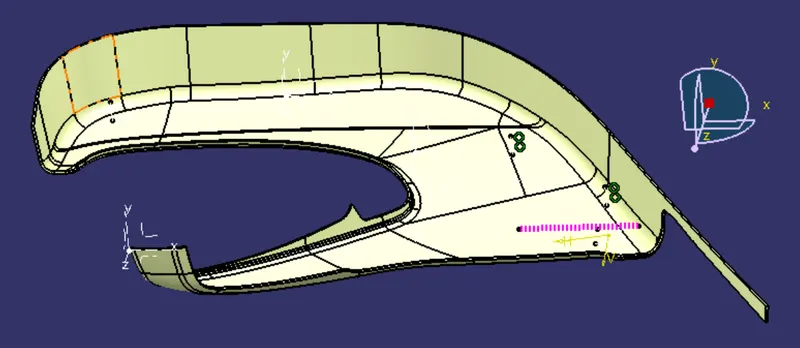
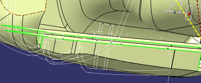
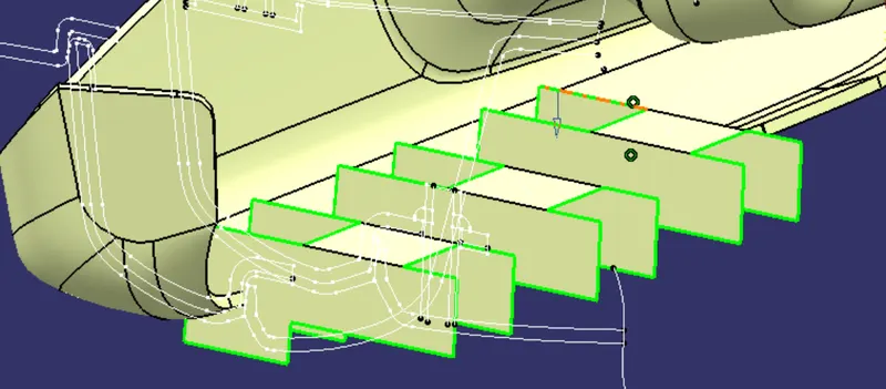
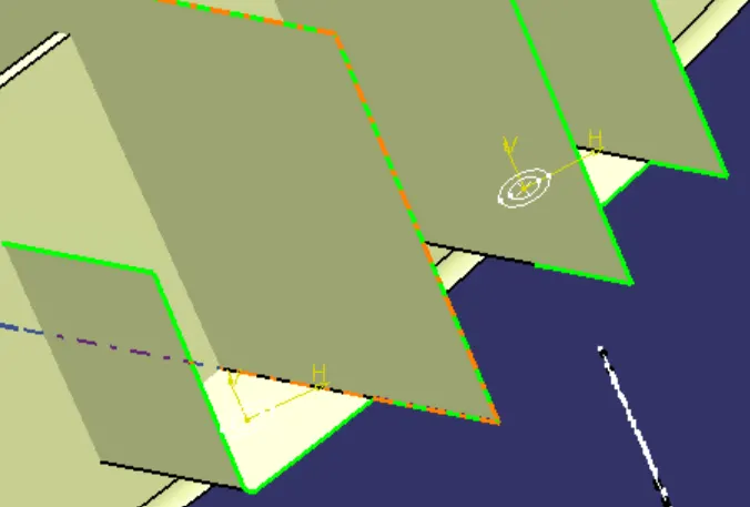
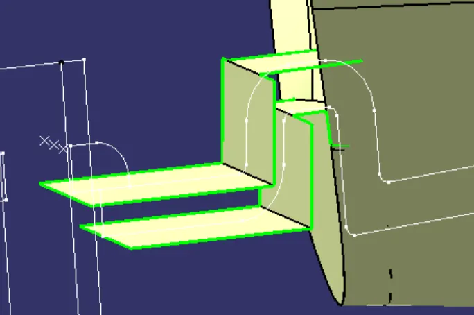
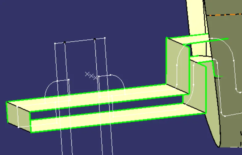
Flange creation :-
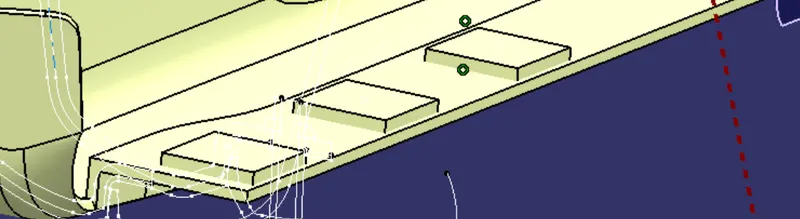
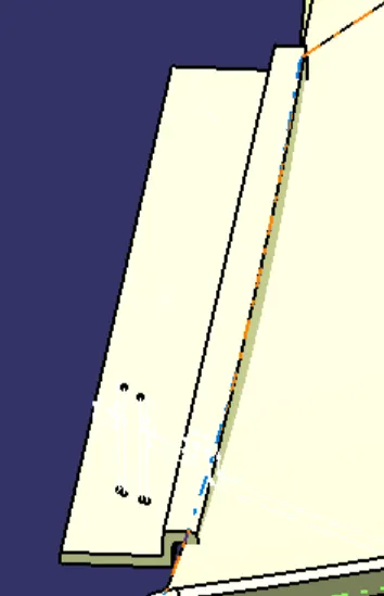
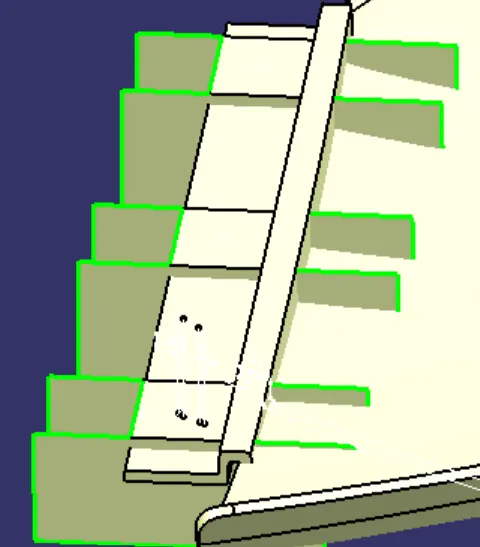
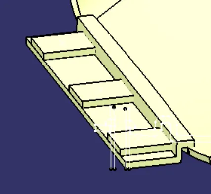
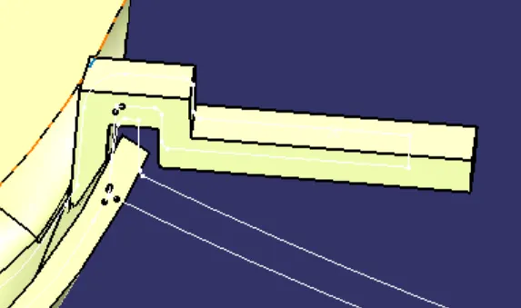
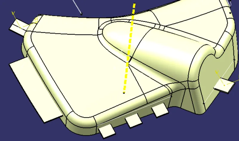
Procedure to create flanges and heat stakes for every part, from given master sections. Use multiple extract to obtain required guide curve and sweep profile for flange top surface. Use sweep option to create a surface from below and top obtained multiple extracts. Use extrapolate to extend the surface according to master section and close them to create a solid body in a new body. Create holes and flat surfaces for heat stake. This way all flanges have to create. In some areas if master secion is not given and flanges are required for those areas then create flanges without master section maintaining engineering standerds.
for armrest-
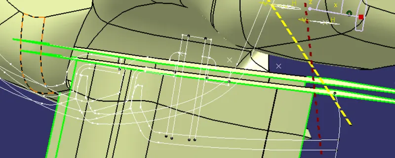
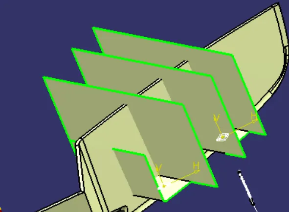
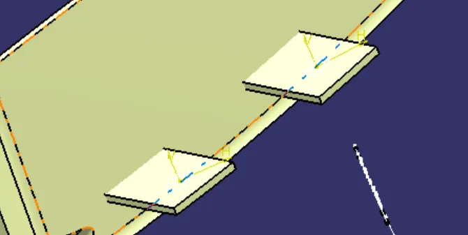
flange for upper map-pocket-
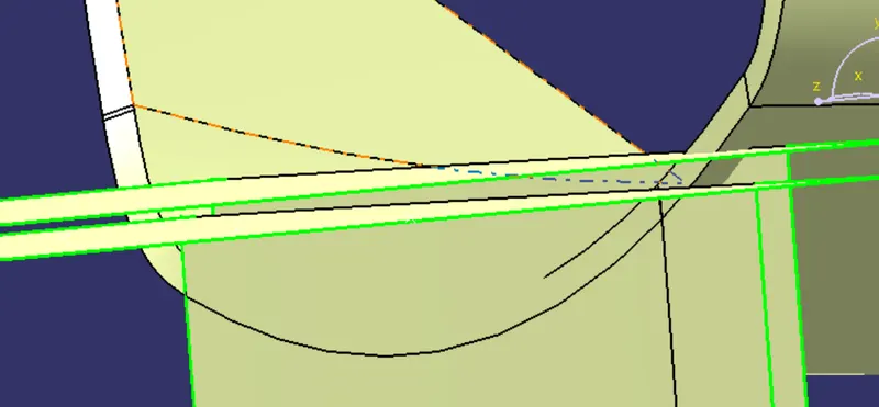
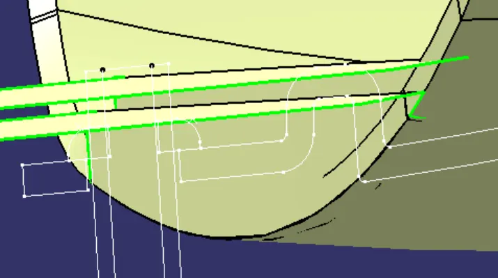
flange for lower map-pocket-
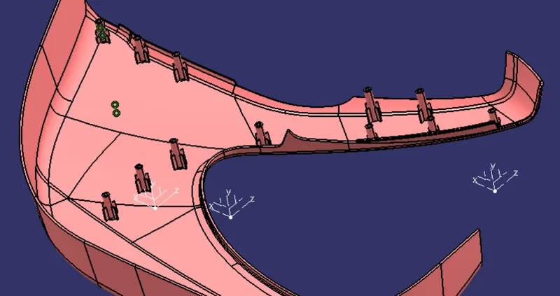
Heat Stake-
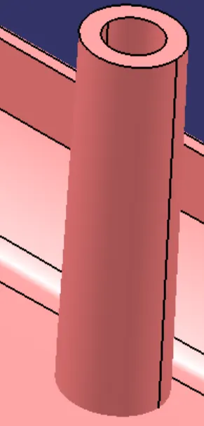
Heat stake was created from padding a sketch created from a point obtained from master section.
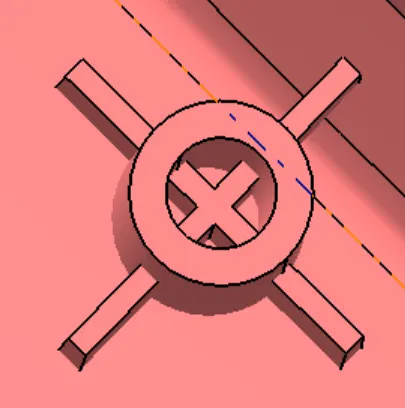
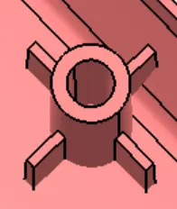
Procedure to create ribs on Heat stakes
- Create a sketch with center as centre of heat stake inner circle .
- Use pad option to create solid body
- Use boolean opetaion union trim to obtian required ribs.
give draft with proper angle. Then copy and pest the solid body with require amount and using 'translation' command place them in right position.
Dog House-
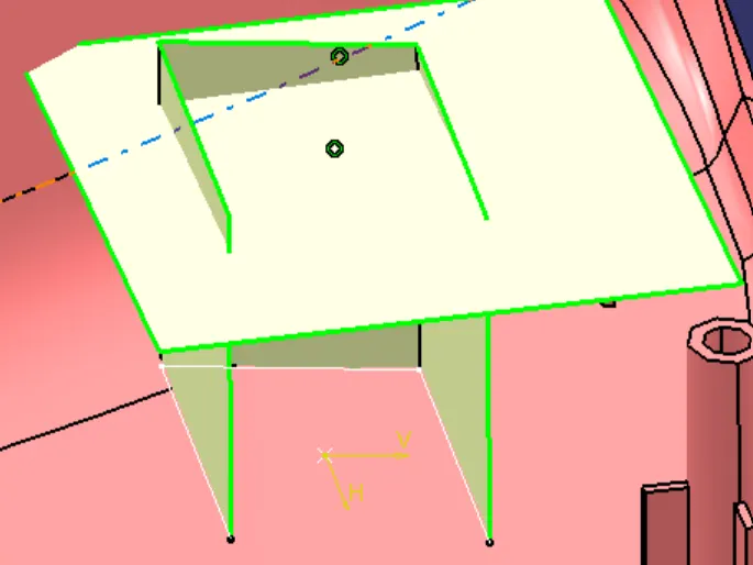
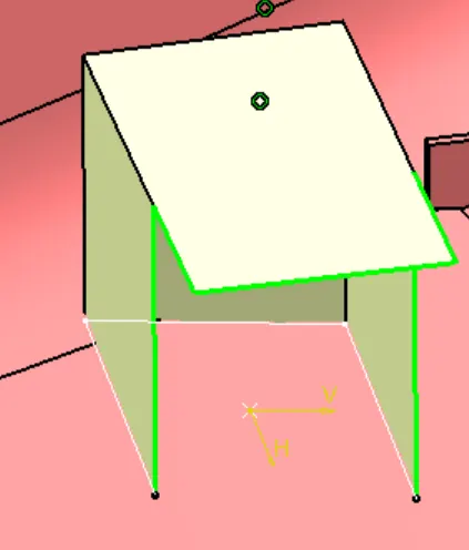
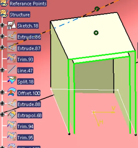
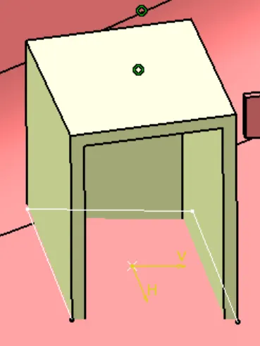
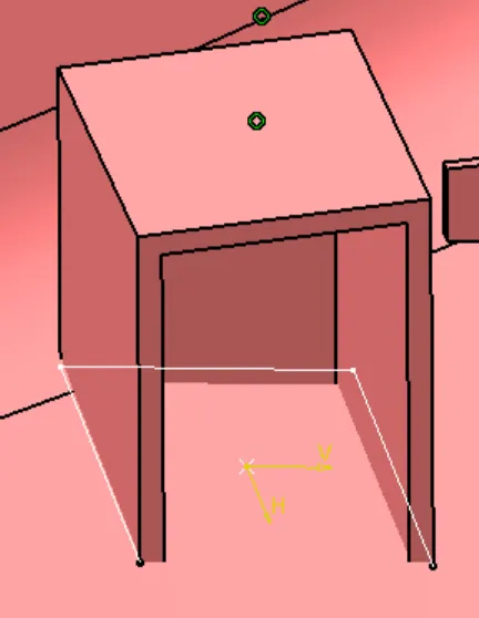
We need to create dog house to attach push clip on lower substraits. Make sure that maintain some space in front of dog house to move and adjust side core easily.
procedure to create dog house-
- Create a point on required location and a plane from it . Create a sketch with base sketch for dog house.
- Use sweep tool to create a surface using this profile and draft direction at a draft angle of 1.5 degrees.
- Use extrapolate and extrude option to create required surfaces and use trim and split to obtain the outer body of dog house.
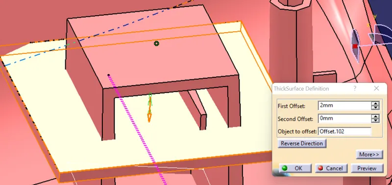
- Create a new body and name it as dog house 1 . Use thick surface option to create a solid of required thickness.
- Translate the dog house to required height using translate option and use thick coomand to extend the base surface to intersect the lower substrate.
- Extract the inner base edge and create a surface to get the required base profile . Use thick surface to create a solid and use boolean operation to remove it from the base of dog house.
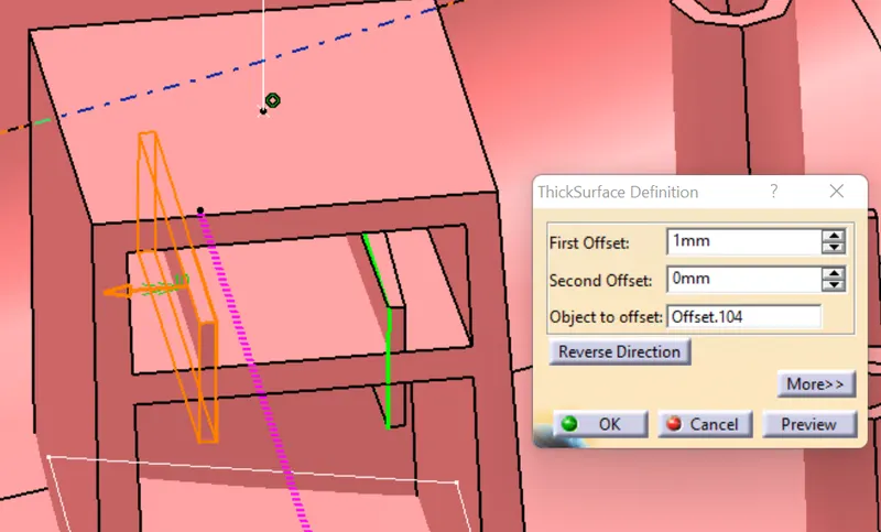
- To create top profile for attachment of push pins , create a stech , extrude it and split it from the solid using split option.
- To create a base for push pins to rest , create another sketch extrude and off set it . Create solids feom it using thick surface option.
- Use boolean operation union trim to obtain required design.
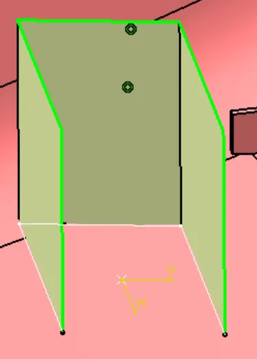
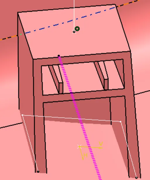
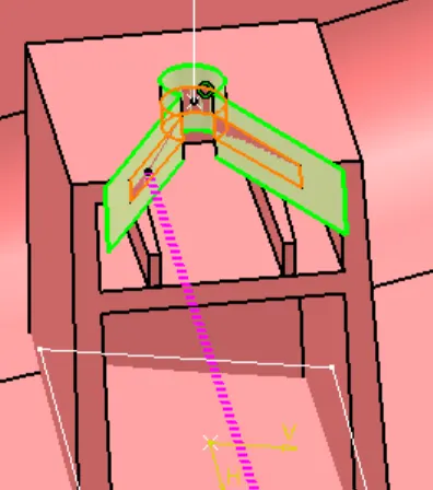
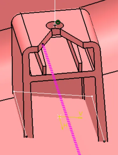
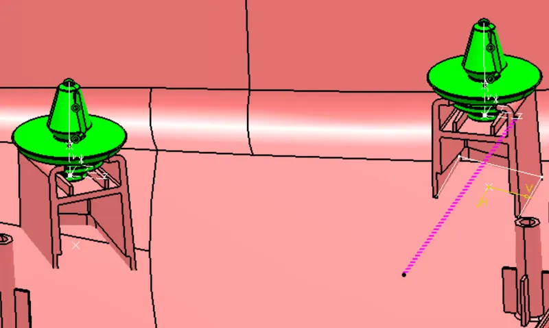
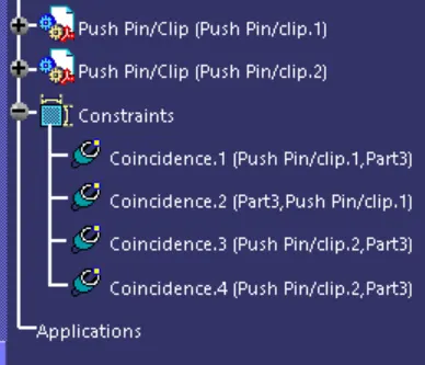
Now attach push clip on top of dog house and give proper constrains-
Final Arm Rest-
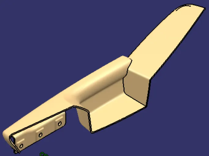
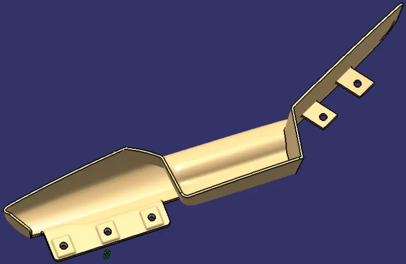
Final Upper map-pocket -
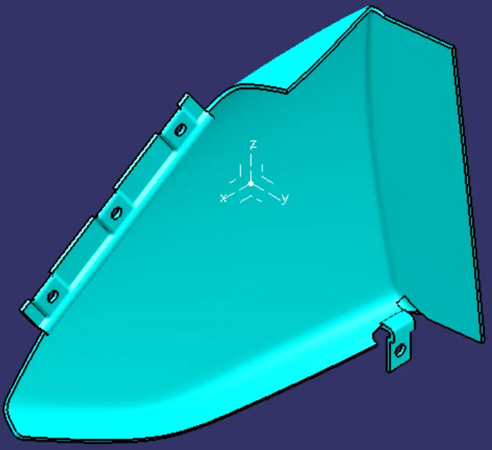
Final lower map-pocket -
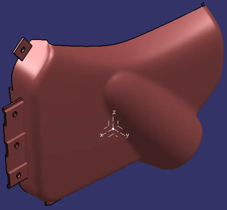
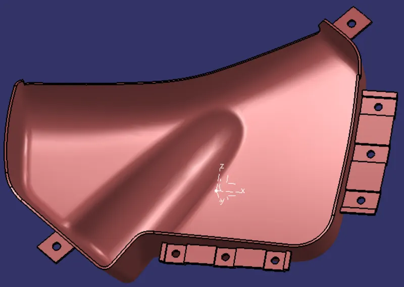
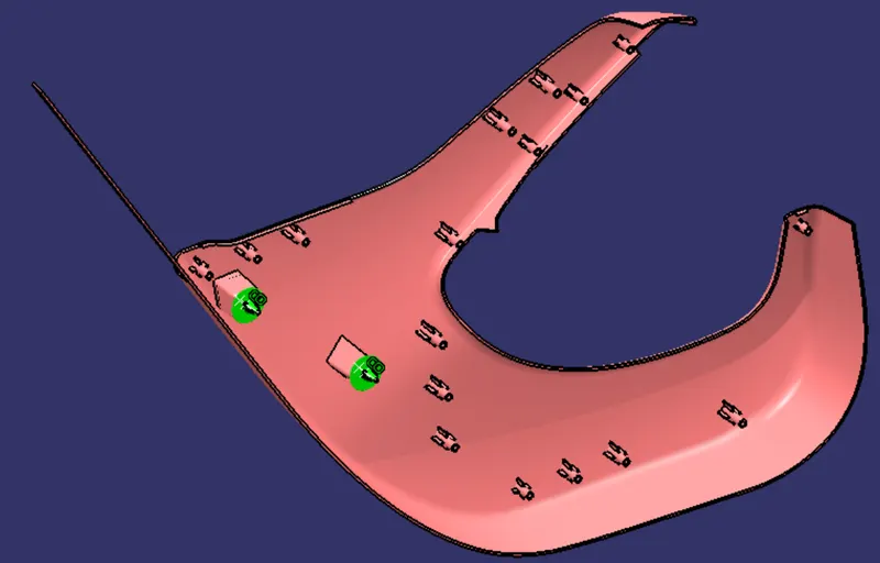
Final lower substrait -
Draft analysis of final parts -
Arm rest:
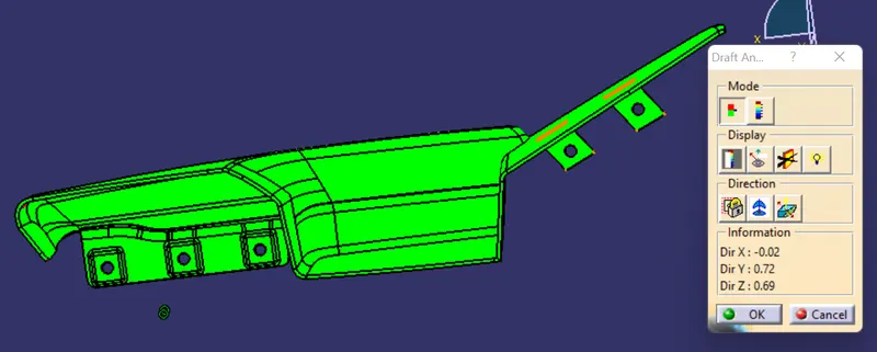
Upper map-pocket:
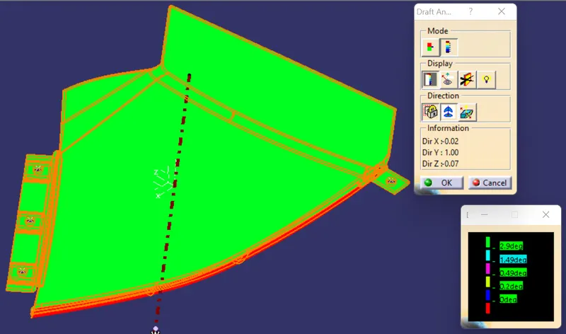
Lower map-pocket:
Lower substrait:
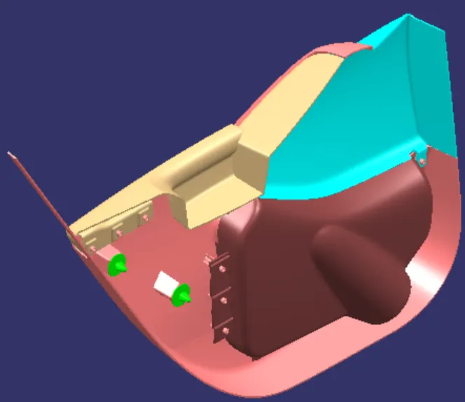
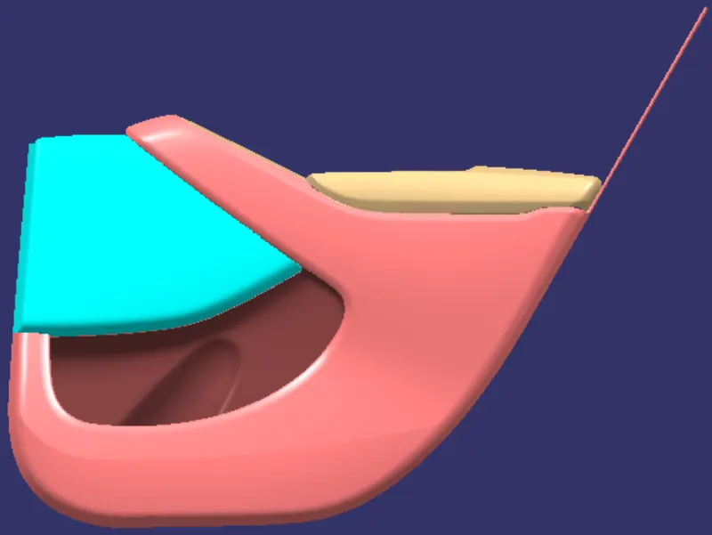
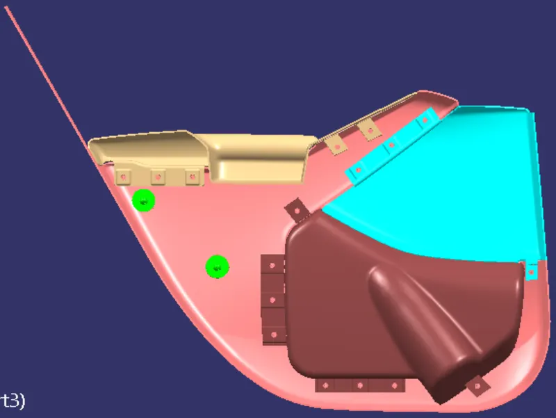
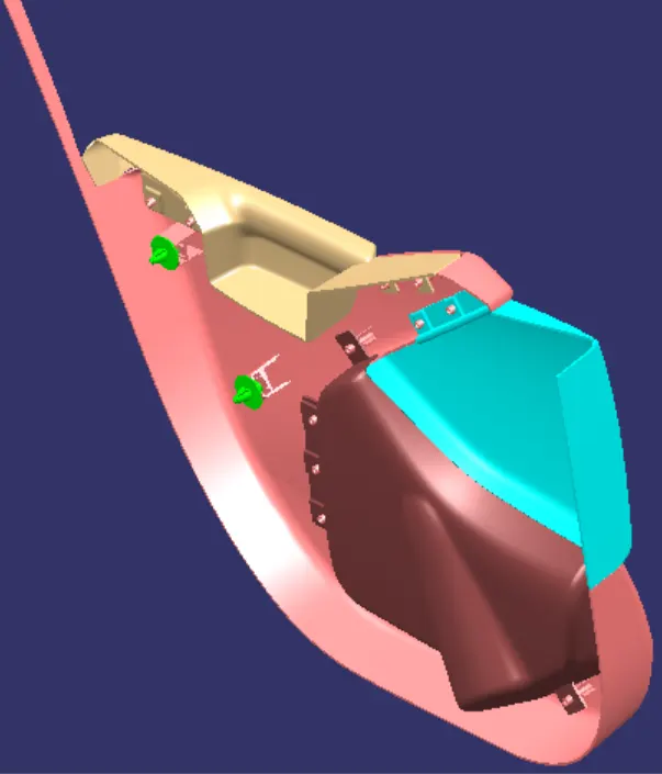
Final assembly model-
- Bharathvaj SGOOD WORK