Week 11 - Final project
Aim:-
To create a CAD model of side door trim panel from the given class A.
Objective:-
1) To create a CAD model from the given class A & create closed body of required thickness.
2) Create the flanges and heatstakes as per the given master section.
3) Create the engineering features like doghouse, ribs,etc.,
4) To create draft analysis.
Introduction:-
The ten stages in automotive product life cycle developement are listed below:
1)Concept sketch
2) Styling class A
3)Feasilbility check
4)Concept validation
5)New product design
6)Product developement
7) Prototyping
8)Design validation
9)Pilot production
10)Mass production
Now, we are in the new product design. We will get input from the class A team and then we need to make it as solid component with the help of desiging software like CATIA V5 with respect to the class A.
Process Of Creating Solid Component:-
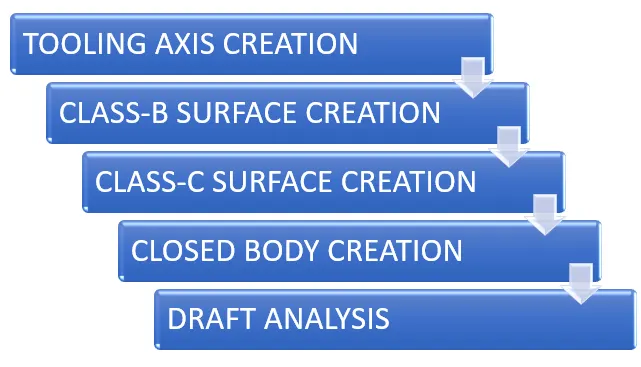
1) Creation of tooling axis
2) Creation of class b surface
3) Creation of class C surface
4) Creation of closed body
5) Draft Analysis .
Class A:-
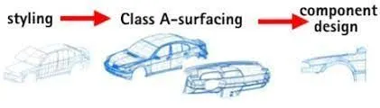
Class A is the aesthetic/styling surface of the automotive component that which we can see with our naked eyes. This is called Class A.
Class B:-
Class B is the also called Engineering surface because this is the place where we need to do lot of works to make its as solid component. Class B is invisible to eyes unlike Class A. Here we need to check the Class A either it is one closed surface or with some discontinueties. If there is any patch in Class A means then we need to first work on Class A to make it as closed surface then only we can ale to make the solid component from the Class A. This surface is behind the Class A.
Class C:-
Class C surface is the surface that connects the Class A and Class B with the slight draft to manufacture the component easily.
Tooling Axis:-
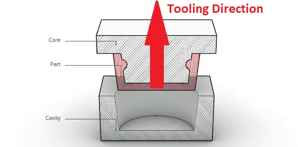
Tooling axis is the line in which the Mold (Core & Cavity) opens and closes while the process of injection molding.
Step-By-Step Process of Creation of Door Trim Panel:-
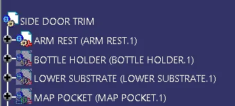
Assemby Workbench:-
First we have to open the assembly workbench by Start ---> Mechanical Design ---> Assembly Design. Then start creating the solid parts separately.
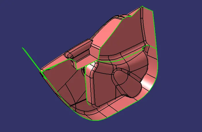
Given Class A:-
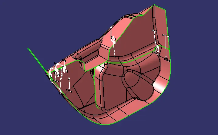
Given Class A With Master Section:-
Step-By-Step Process Of Creating Solid Parts:-
1) Arm Rest:-
First check the quality of surface by the boundary command. Then if incase the Class A has any patch or discontinuity then we have to work on the patches to make the suface better.
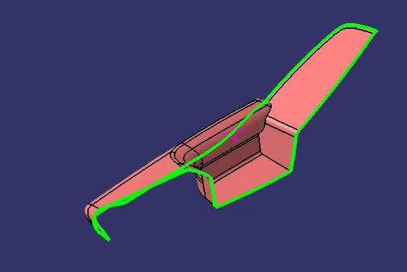
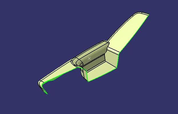
This is the improved Class A after fixing the patches or discontinuities. After fixing the errors this is our Class A further we have to work with this surface.
Creation Of Tooling Axis:-
Tooling axis can be created by the folowing steps:
1) By Reference Method
2) By Normal To Surface
3) By Bisecting Method
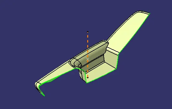
Here i used Center of gravity point to create tooling axis.
Then create a line perpendicular to the surface on the point is called tooling axis. Then make the line thicker and bigger to make it better visible and publish this to access easily.
Draft Analysis of Class A:-
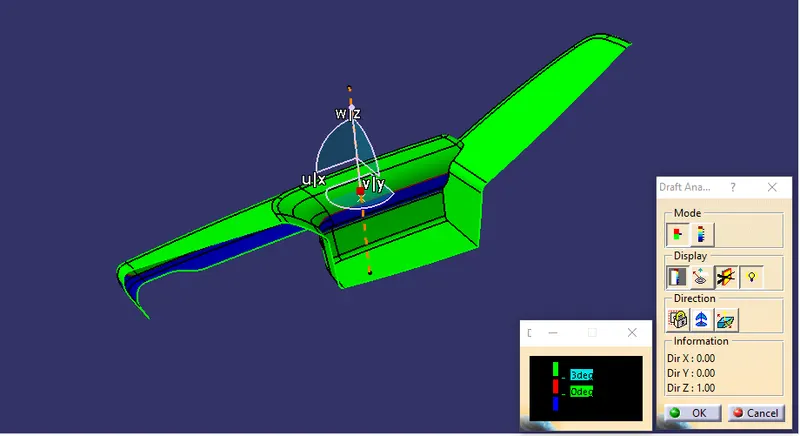
After creating the tooling axis then we should do draft analysis on the Class A. Here this Class A is not clearing with the max 3 degree draft.
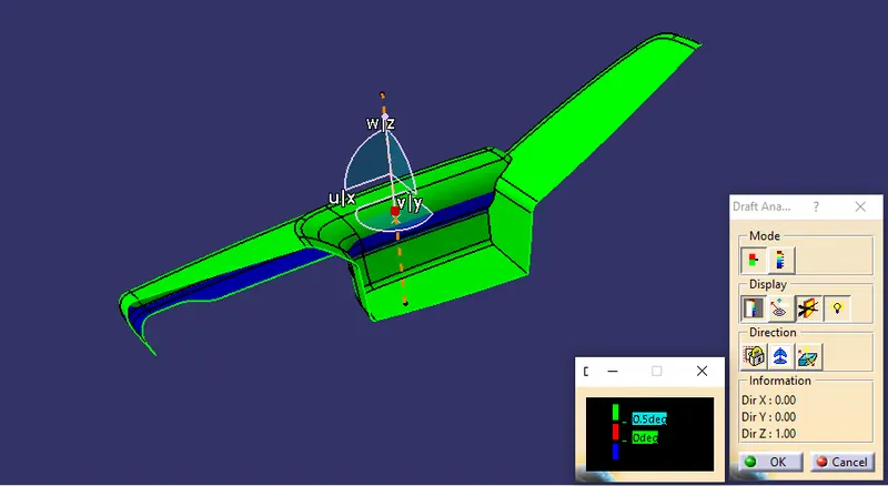
Then i given the min draft 0.5 degree draft. Eventhough after giving the minimum draft this surface is not clearing then the problem is with our Class A.
Creation Of Class B Surface:-
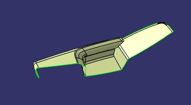
To start the creation of Class B first we have to change to the surface workbench by Start ---> Mechanical Design ---> Part Design. Then we need to offset the surface to the required thickess and then do some work on the offseted surface if there is any patch.
Creation of Class C Surface:-
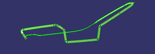
Create the sweep with the Class A. Here if the edges of the surface is parallel to the tooling then we can give sweep with tooling direction with the draft 3 degree. Incase if the edges are perpendicular to the tooling axis means then we have to give draft with reference to the surface with either 93 or 87 degree draft that is depend upon the model we have to choose upon.
Joining Class A with Class C:-
Creation of Plastic Surface:-
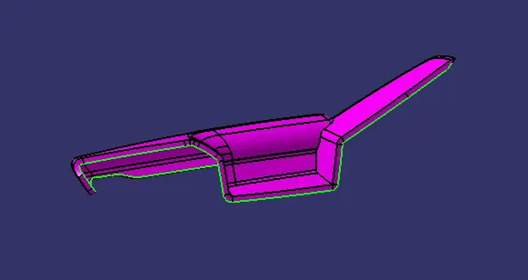
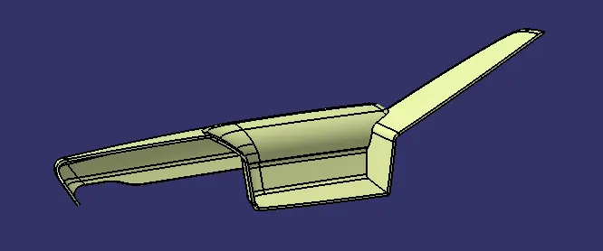
After joining the Class A with Class C then try to extrapolate the B surface to cross te A+C. Then use trim command to remove the unwanted surface edges. Finally we got the Plastic surface.
Creation of Solid Component:-
Change to the part workbench by Start ---> Mechanical Design ---> Part Design. Use the closed surface command to create the solid component.
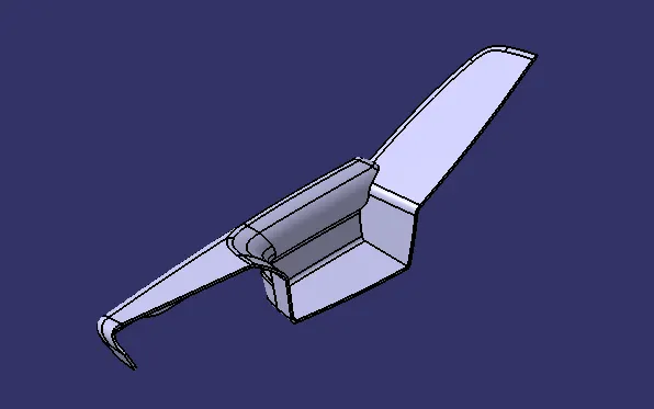
2) Bottle Holder:-
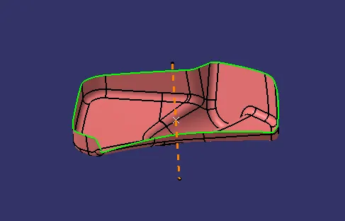
This is the given class A.
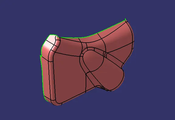
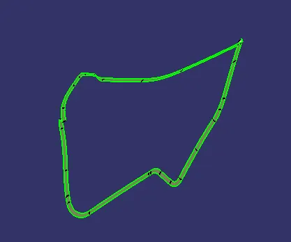
Checking the quality of surface by boundary command.
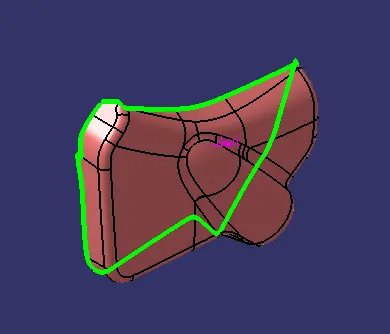
Creation of Tooling Axis:-
Here i used the toolng axis by Centre Of Gravity point.
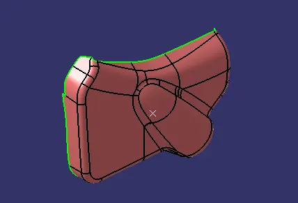
Then create the line perpendicular to the surface on the point. Make the line thicker and darker to make them visible easily.
Draft Analysis Of Class A:-
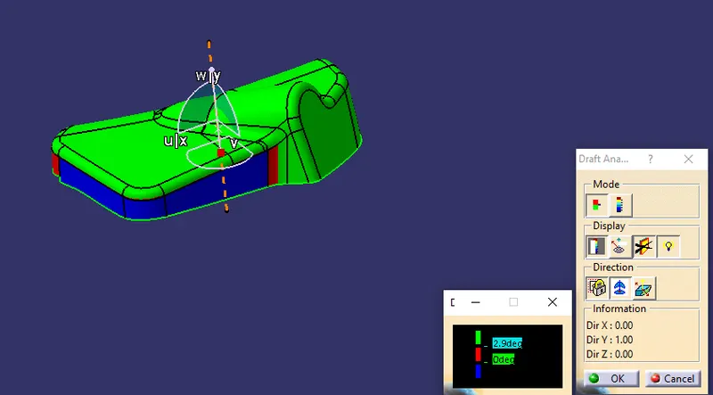
After creating the tooling axis we need to check the draft analysis of Class A. Here i tried draft analysis by the tooling axis created by all the three method but this Centre Of Gravity point alone can clear the max surface. That's why i used this point for all the surface. Here with the max draft 3 degree is not clearing.
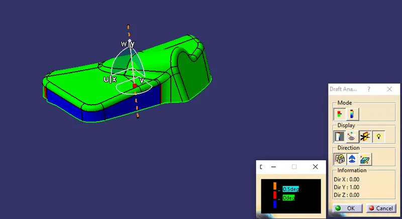
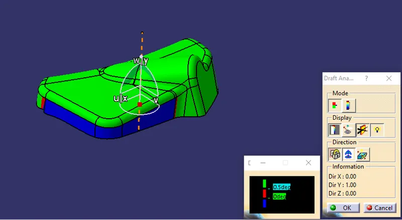
Then i given the min draft 0.5 degree, eventhough with the min draft itself it's not clearing. If the Class A surface is not clearing with this tooling axis means then the solid surface also will not clear.
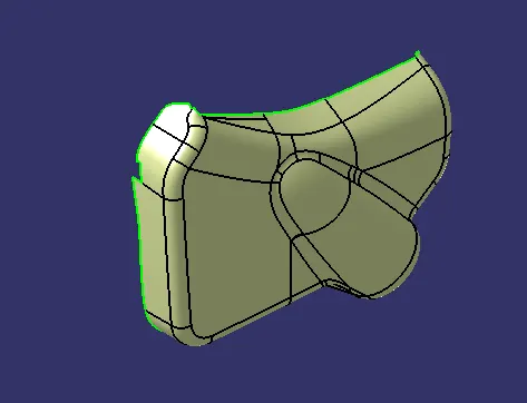
Creation Of Class B Surface:-
To start the creation of Class B first we have to change to the surface workbench by Start ---> Mechanical Design ---> Part Design. Then we need to offset the surface to the required thickess and then do some work on the offseted surface if there is any patch.
Creation Of Class C Surface:-
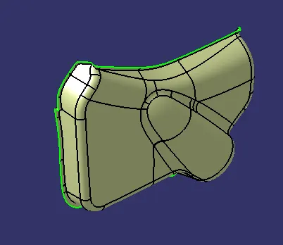
Here i use sweep command with reference to surface with 93 degree because the sweeping surface is perpendicular to the tooling axis.
Joining Of Class A with Class C:-
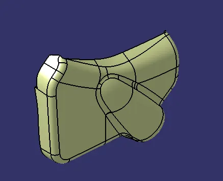
Creation of Plastic Surface:-
After joining the Class A with Class C then try to extrapolate the B surface to cross te A+C. Then use trim command to remove the unwanted surface edges. Finally we got the Plastic surface.
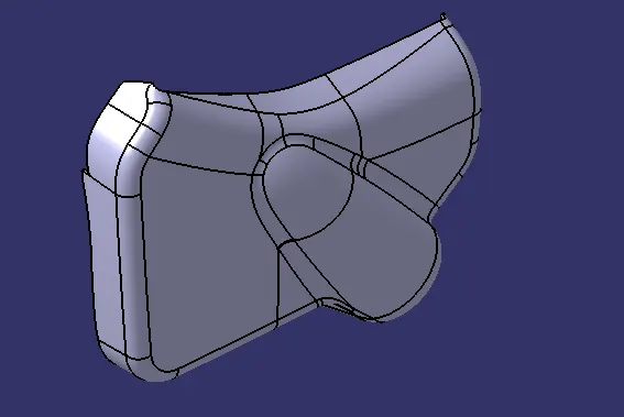
Creation of Solid Component:-
Change to the part workbench by Start ---> Mechanical Design ---> Part Design. Use the closed surface command to create the solid component.
Draft Analysis on Solid Component:-
Here the small area of the solid component is not clearing because the Class A itself it's not clearing so the same problem arising here too. So no need to worry about this. Here i've given the max draft angle 3 degree it's not clearing.
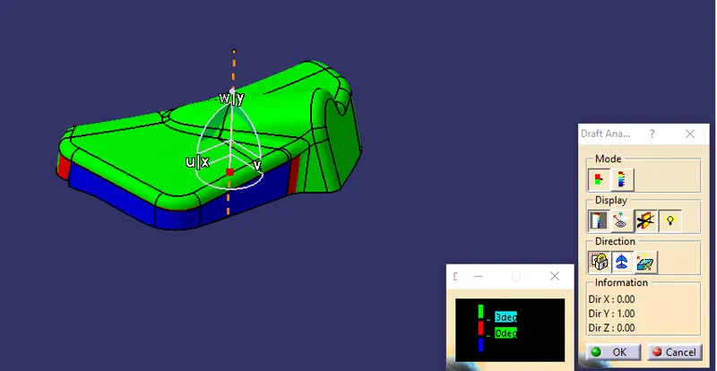
With the min draft 0.5 degree draft itself it's not clearing. So the problem is with Class A.
3) Lower Substrate:-
Given Class A.
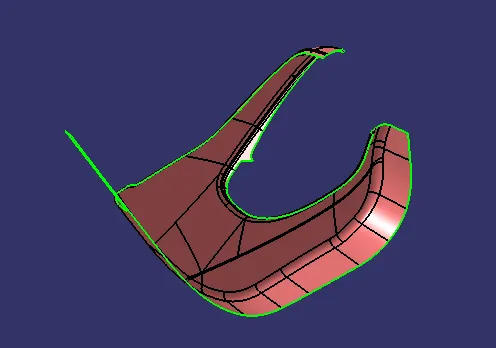
Checking the quality of surface by boundary command.
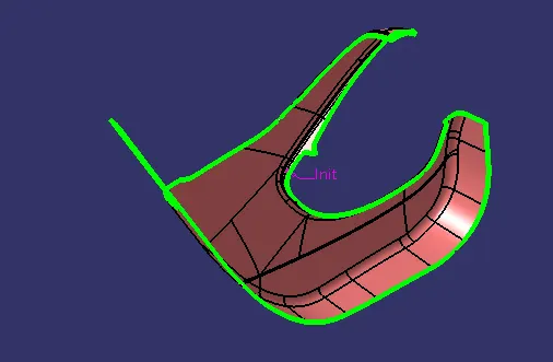
Creation of Tooling Axis:-
Here i used the toolng axis by Centre Of Gravity point.
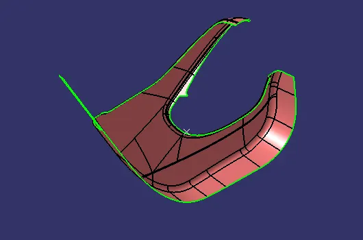
Then create the line perpendicular to the surface on the point. Make the line thicker and darker to make them visible easily.
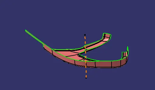
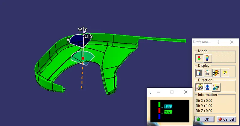
Draft Analysis on Class A:-
Here i used CG point to create the tooling axis with the max draft 3 degree is clearing.
Creation Of Class B Surface:-
To start the creation of Class B first we have to change to the surface workbench by Start ---> Mechanical Design ---> Part Design. Then we need to offset the surface to the required thickess and then do some work on the offseted surface if there is any patch.
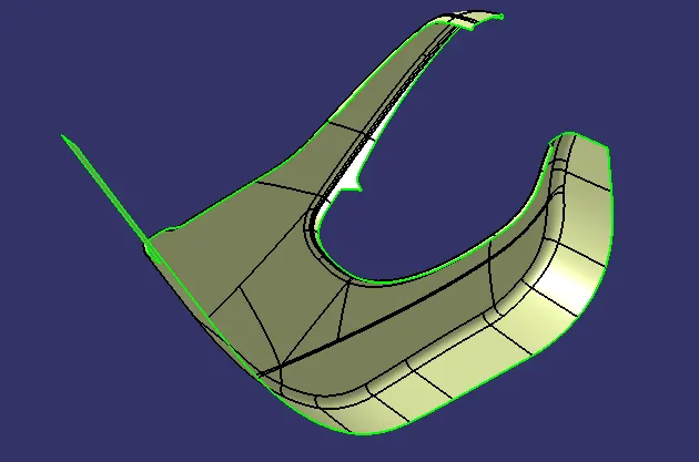
Creation Of Class C Surface:-
Here i use sweep command with reference to surface with 93 degree because the sweeping surface is perpendicular to the tooling axis.
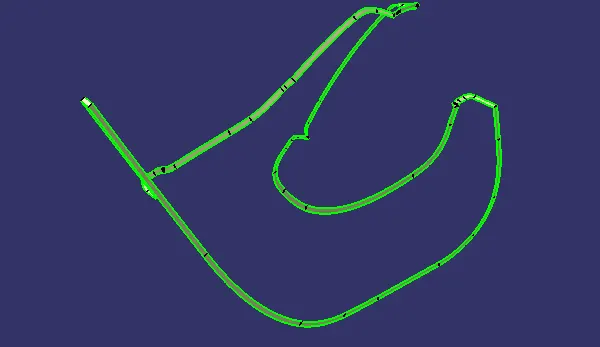
Joining Of Class A with Class C:-
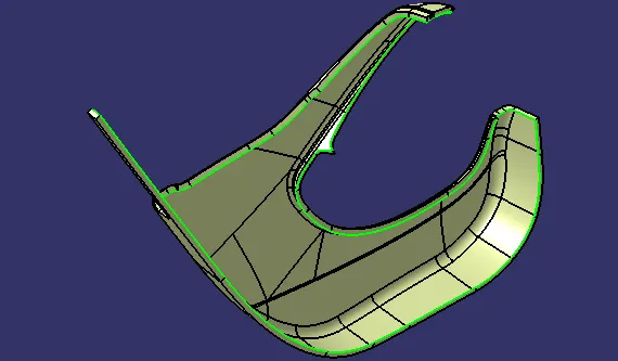
Creation of Plastic Surface:-
After joining the Class A with Class C then try to extrapolate the B surface to cross te A+C. Then use trim command to remove the unwanted surface edges. Finally we got the Plastic surface.
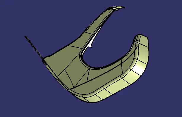
Creation of Solid Component:-
Change to the part workbench by Start ---> Mechanical Design ---> Part Design. Use the closed surface command to create the solid component.
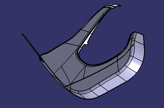
Draft Analysis on Solid Component:-
Here the whole surface is clearin with 3 degree because the whole Class A is clearing.
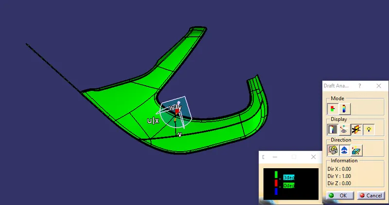
4) Map Pocket:-
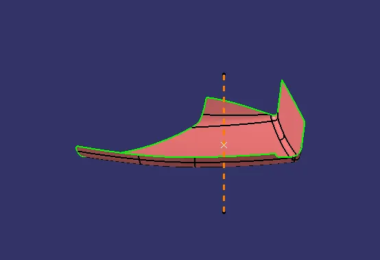
Given Class A.
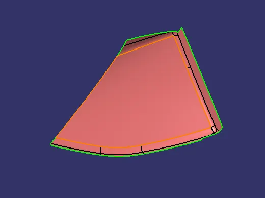
Checking the quality of surface by boundary command.
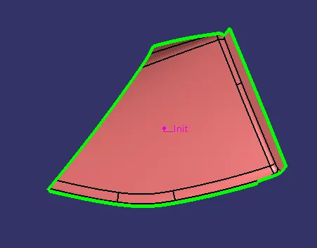
Creation of Tooling Axis:-
Here i used the toolng axis by Centre Of Gravity point.
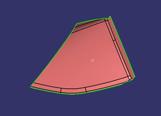
Then create the line perpendicular to the surface on the point. Make the line thicker and darker to make them visible easily.
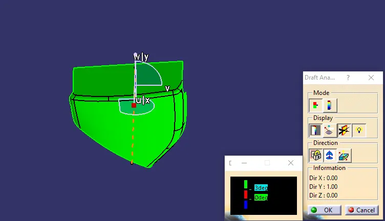
Draft Analysis on Class A:-
Here i used CG point to create the tooling axis with the max draft 3 degree is clearing.
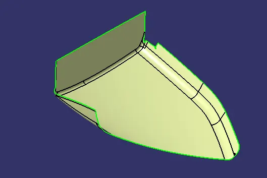
Creation Of Class B Surface:-
To start the creation of Class B first we have to change to the surface workbench by Start ---> Mechanical Design ---> Part Design. Then we need to offset the surface to the required thickess and then do some work on the offseted surface if there is any patch.
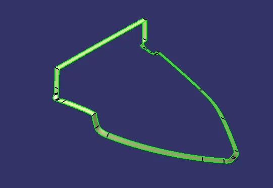
Creation Of Class C Surface:-
Here i use sweep command with reference to surface with 93 degree because the sweeping surface is perpendicular to the tooling axis.
Joining Class A with Class C:-
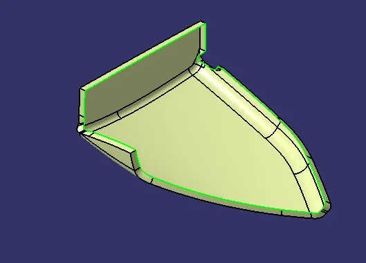
Creation of Plastic Surface:-
After joining the Class A with Class C then try to extrapolate the B surface to cross te A+C. Then use trim command to remove the unwanted surface edges. Finally we got the Plastic surface.
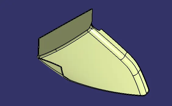
Creation of Solid Component:-
Change to the part workbench by Start ---> Mechanical Design ---> Part Design. Use the closed surface command to create the solid component.
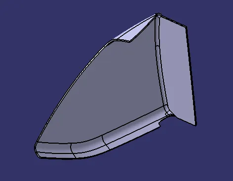
Draft Analysis on Solid Component:-
Here the whole surface is clearin with 3 degree because the whole Class A is clearing.
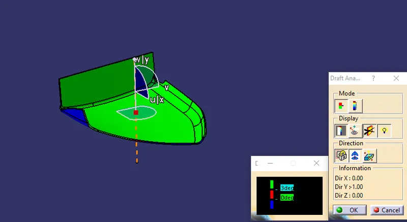
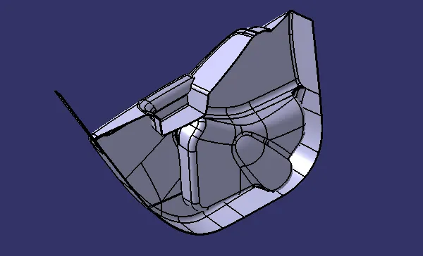
Assembled Components without Engineering Fearures:-
Creation of Engineering Features with Master Section:-
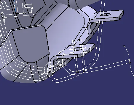
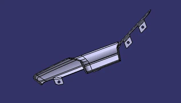
1) Arm Rest:-
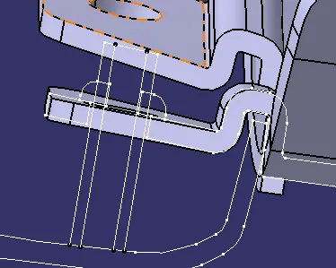
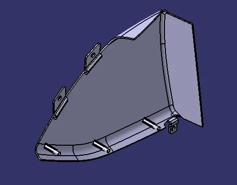
Creating Flanges in Arm Rest according to the Master Section. Flanges are like use to position the component in place with the heatstakes or screw bosses.
2) Bottle Holder:-
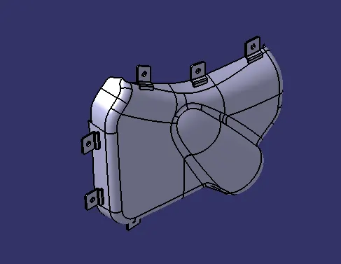
3)Lower Substrate:-
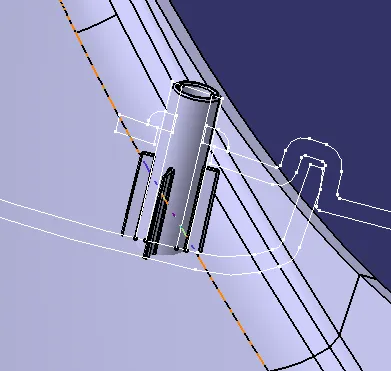
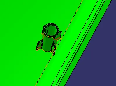
Creating the heat stakes as per the master section. Here the heat stake and flanges are joined by the means of heating the heatstake and using the pressuried hand to press to make it sit in correct position with the flanges.
Creation of Dog House:-
Create the sketch for the dog house and pad it to make it as solid and give the required draft here i've given 1.5 degree for outer and make shell and again draft the inner side with 0.5 degree. Before giving the draft for the inner side we need to create side core axis with the help of side core axis only we can draft the inner surface.then create the hole and inner rib in the doghouse.
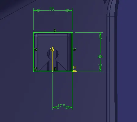
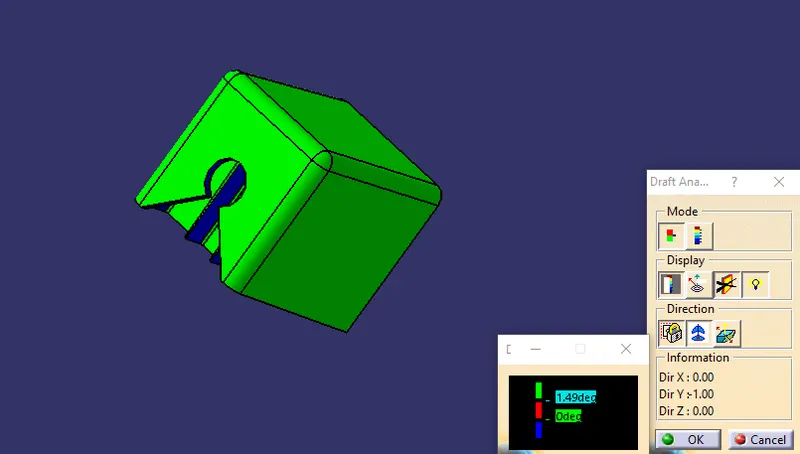
This is the dog house we need to draft analysis before join it with the lower substrate.
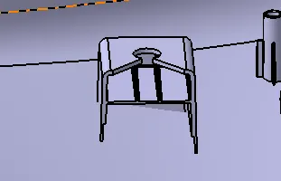
Draft Analysis on Dog House:-
Here with the side core axis i've checking the draft for inner side of dog house with 0.5 degree. There will some minor deviations in the angle so change it to 0.49 degree.
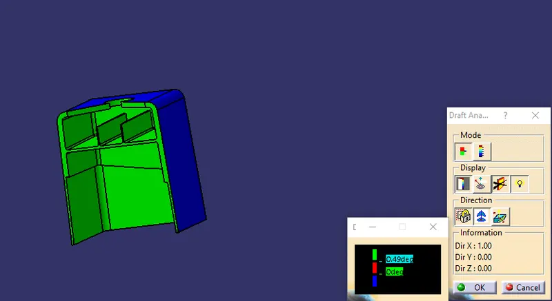
Checking the outer surface of dog house with main tooling axis with 1.5 degree draft.
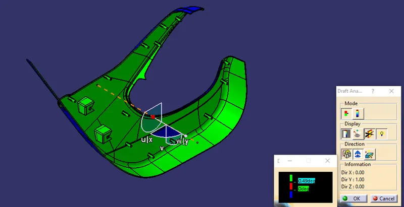
Draft analysis on lower substrate after attaching all engineering features as per the master section the whole surface is clearing with the 0.5 degree because the draft given to the heat stakes is 0.5 degree.
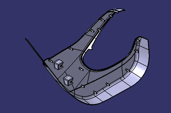
Solid Component with Engineering Features:-
4) Map Pocket:-
Creating Flanges as per the master section.
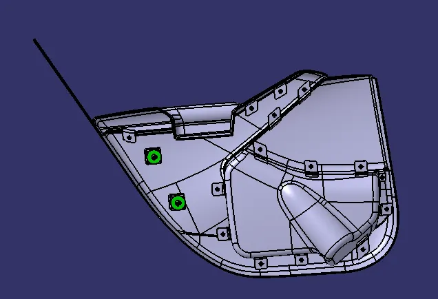
Door Trim Panel with Engineering Features:-
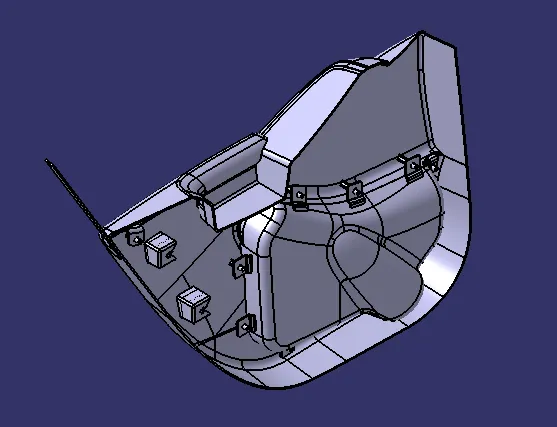
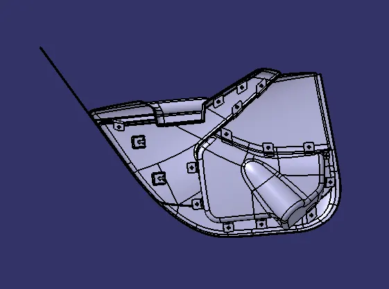
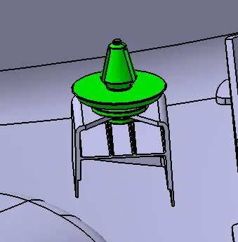
After assembling the Push pins with dog house:-
Final Door Trim Panel:-
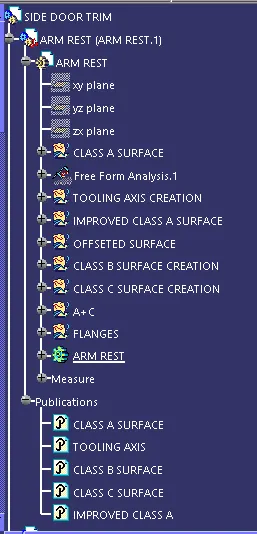
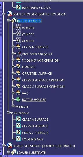
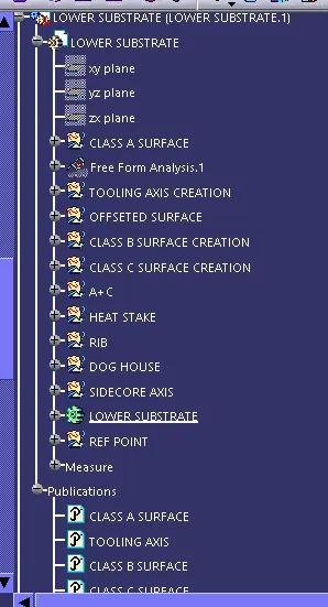
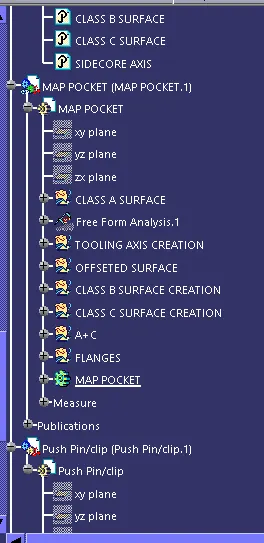
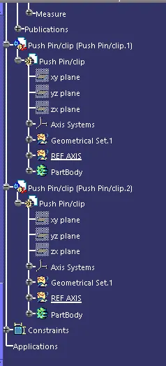
Expanded Tree Structure:-