Week 11 - Final project
AIM
To create a door interior part from the inputs of class A surface along with master section by following the design rules followed in tier 1 and OEM industries in catia v5
CLASS A SURFACE
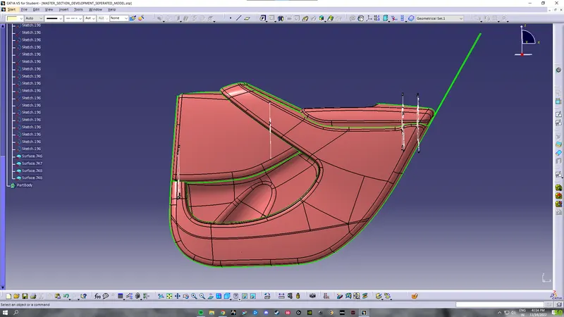
REPORT
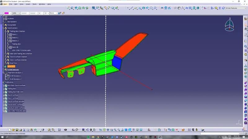
CREATING THE TOOLING AXIS
The tooling axis creation was possible when a point command was taken and on that window "on surface" was executed to get the desired point on the Class A. Then using line command and giving a Y direction gave us the required tooling axis.
For the Side-Core Tooling Axis, the same procedure is follwed. The only change here is the direction at which the line is extruded.
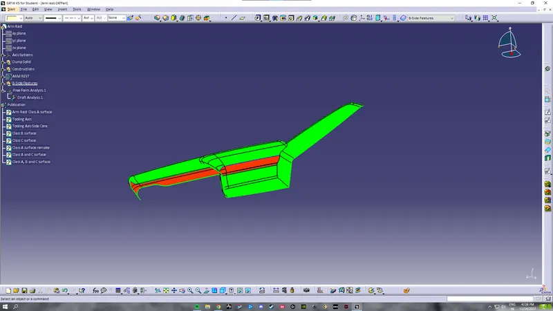
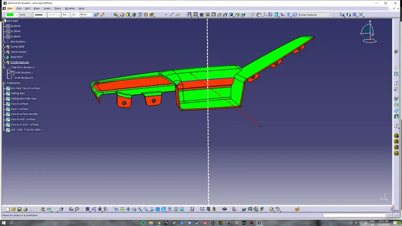
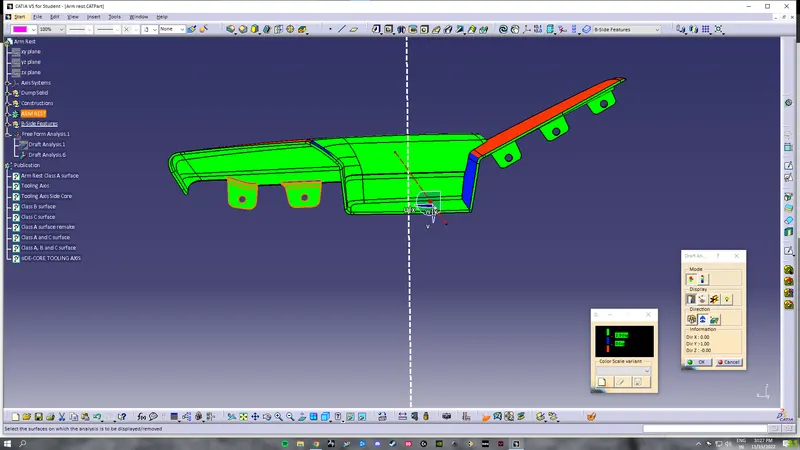
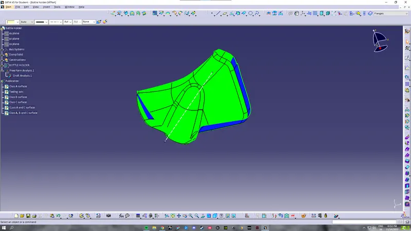
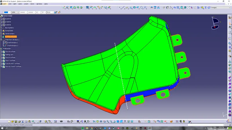
DRAFT ANALYSIS REPORT OF CLASS A
- We need to align the compass on tooling axis that we created
- Open the color scale and enter the value is 2.9 deg.
- If the whole body is green that all the faces is greater angle than the provided angle
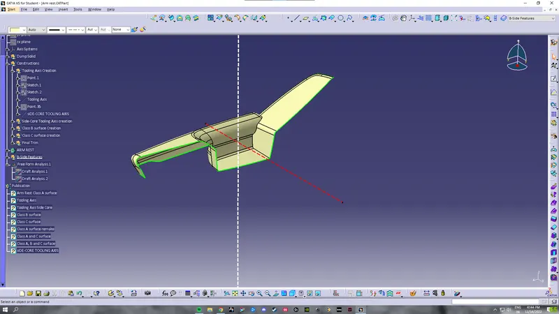
CREATION OF CLASS B SURFACE
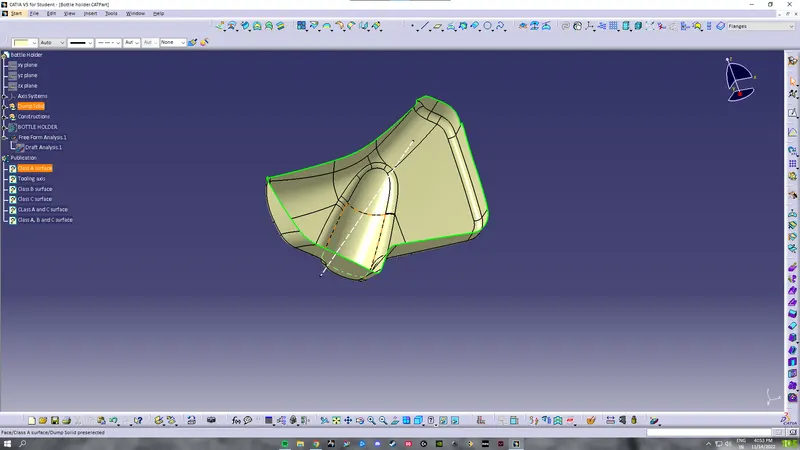
For creation of Class B first we need check the boundary ofthe Class A. If the Class A surface is good then we proceed onto making the Class B.
- Insert a new geomtrical set. Measure the value of thickness in master section.The value is 2.5mm
- Offset the class A surface to 2.5mm.
- Check all the sub elements are formed.
- If all the necessary surface are not forming then we use other surface cretaion commands to make the required surface.
- We also extrapolate the B surface overall using extrapolate command to make sure that it intersects with the Class A and C surface which we will create later.
CREATION OF CLASS C SURFACE
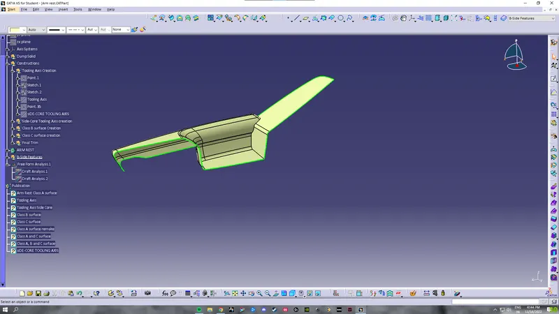
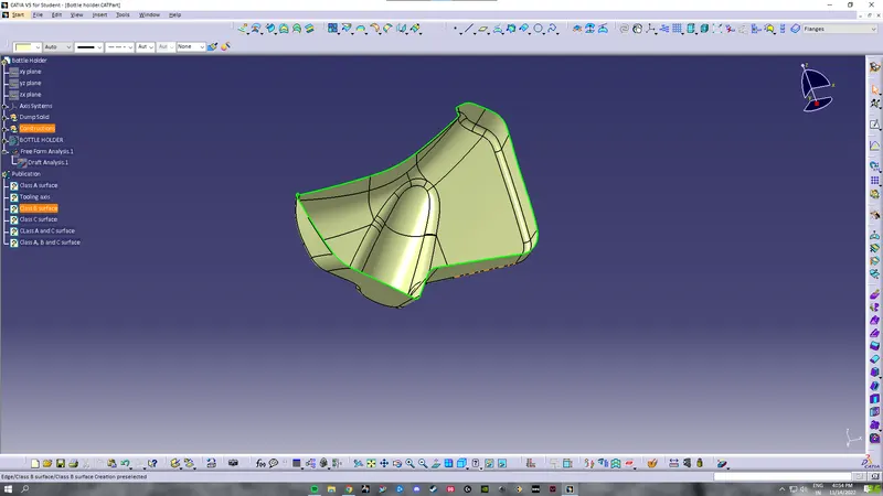
- First we need to unhide the Class A and then start by creating a boundary of the required edge.
- Then we need to create the Class C by "Sweep" command usingthe tooling axis which we created earlier.
- After that we join all the C surfaces by Join command.
CREATION OF CLASS A & C SURFACE
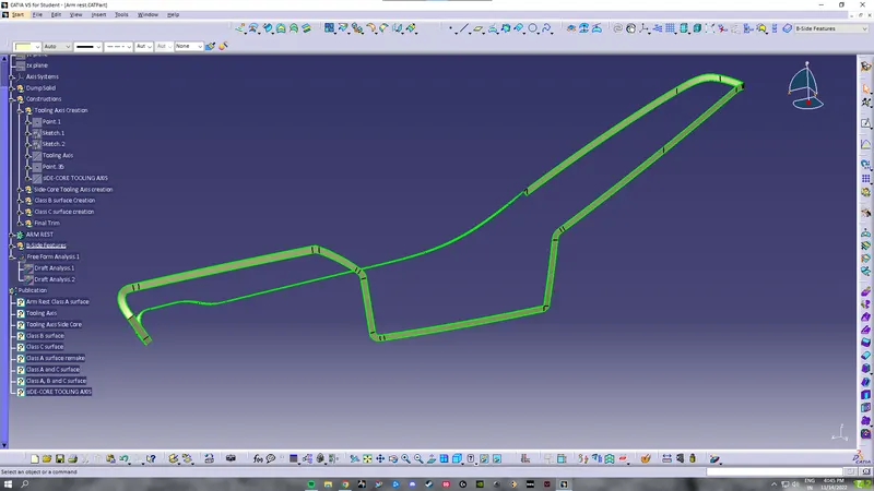
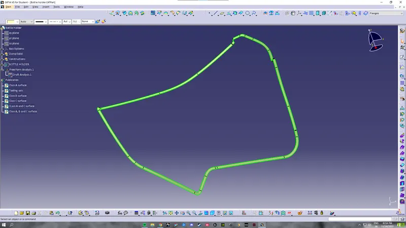
- After creating the Class C surface we then join the Class C surface with the Class C surface.
CREATION OF CLASS A , B & C SURFACE
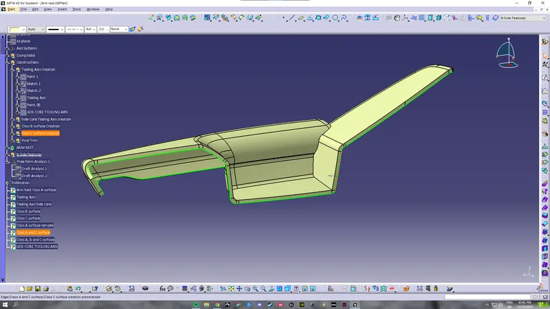
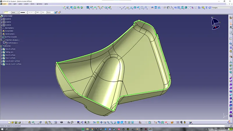
- With the extrapolated B surface we trim the Class A and C surface to get the hollow solid we reuire.
- We also use the boundary command to check if there is any open edges in the solid. If there is no openings, then the commands gives us an error.
- After that we switch our workbench to part design from surface workbench and use a command called "Closed Surface". It helps us to the the final product.
CREATION OF B-SIDE FEATURES:
Dog house rule
B=5mm
t=2.5mm
C=0.4 * t=1mm
DOG HOUSE:-
- For the dog house we first take a point by the command pont on surface and create an axis system on the point.
- Then we draw an positioned sketch and sweep it by giving a 1.5 degree draft and taken the draft direction as the tooling axis.
- Then we switch to the part workbench and apply thick surface command and give the desired value.
- After that we extract the base of the dog house and offset it to 5mm.
- We also extract the inner walls of the dog house and then trim it with the offseted face.
- After that we again offset the trim to get the C.
- Finally we split the surface of the dog house with the final offest.
- We also draft all the inner faces of the dog house by taking the nuetral element as the back wall of the dog house. A minimum of 0.5 deg draft is given to the inner faces of the dog house.
- We then create a side core tooling axis for the dog house.
- After that we again do a sketch, pad it, draft it by taking the side core tooling axis and then union trim it with the main dog house.
- We apply the necessary fillets.
- And for the top of the dog house, we take the radius of the connecting rod of the push pin anddraw the necessary skecth at the top of the dog house.
- We then pad it and then remove it with the main dog house.
- Finally, we draw another point on the solid body suing the point on surface command and copy the main body and paste it with link to the main part and translate it to our desired point.
HEAT STAKES:-
- For creation of the heat stakes we unhide the mastersection and draw a plane using parallel through points option and sketch on it.
- Then we pad the body, apply draft of 0.5 deg and apply minimum fillet of 0.5 to it.
- After that we do the same copy and paste with link command and create as many copies we need.
- Then we add our points to translate the heat stakes.
- A minimum of 50mm is distance maintained between 2 heat stakes.
- Finally we union trim it with the main solid.
4-WAY LOCATORS:-
- For our 4-way locators, we first draw a point on the surface and insert an axis system taking the reference of that point.
- Then we sketch a "+".
- After that we pad it to our desired hieght.
- Then we do a draft of 0.5 deg.
- After that we add our necessary chamfers and fillets.
- Finally we copy paste our feature and translate it as we did with the heat stakes and union trim it with our main body.
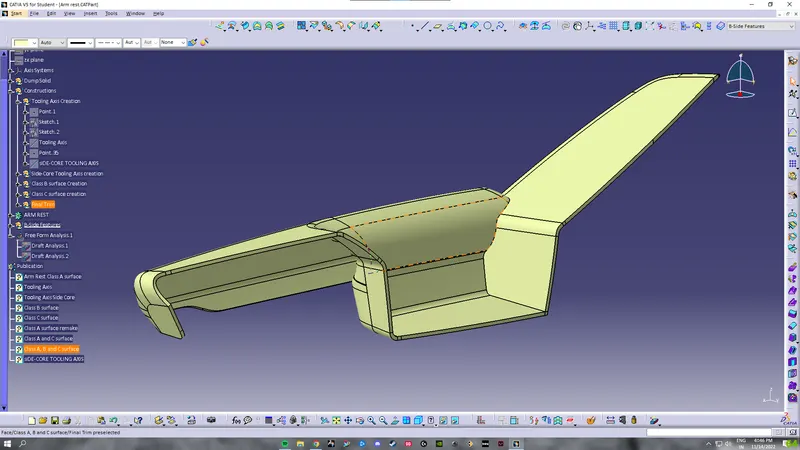
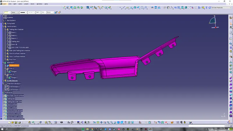
FLANGES:-
- For the flanges we need the help of our master section again.
- We draw a plane using parallel through points option and skecth on it.
- Then we used profile or lines as per the given mastersection and coincide the lines with the mastersection.
- We then sweep it by extracting the required edges.
- After that we used points on curve and lines to split the sweep to get the required design intended.
- Then we go to the thick surface command and thicken it .
- After that we we give fillets and union trim it with the solid body.
FINAL DRAFT ANALYSIS
The final draft analysis is done to make sure that the final solid including the B-side features are made is according to the required draft.
ASSEMBLY
Last but not the least we open a new product file and assemble all the part together by giving proper constraints to them which gives us our final assembly.
- ARM REST
- BOTTLE HOLDER
- DOOR LOWE SUBSTRATE
- DOOR UPPER SUBSTRATE
- PUSH PIN
- PUSH PIN 2(COPY OF THE PUSH PIN)
CREATION OF ALL SURFACES
A. ARM REST
DRAFT
TOOLING AXIS
CLASS B SURFACE
CLASS C SURFACE
CLASS A AND C SURFACE
FINAL SOLID
FINAL SOLID WITH FLANGES
FINAL DRAFT ANALYSIS
B. BOTTLE HOLDER
DRAFT
TOOLING AXIS
CLASS B SURFACE
CLASS C SURFACE
CLASS A AND C SURFACE
FINAL SOLID
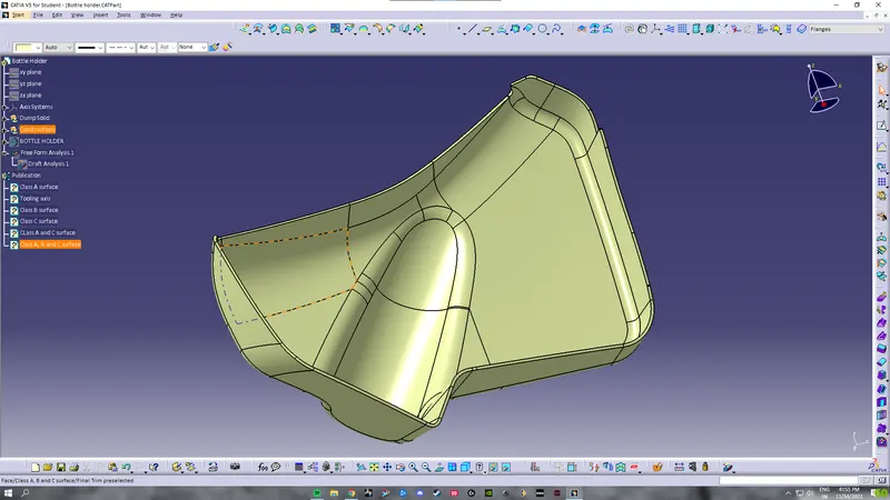
FINAL SOLID WITH FLANGES
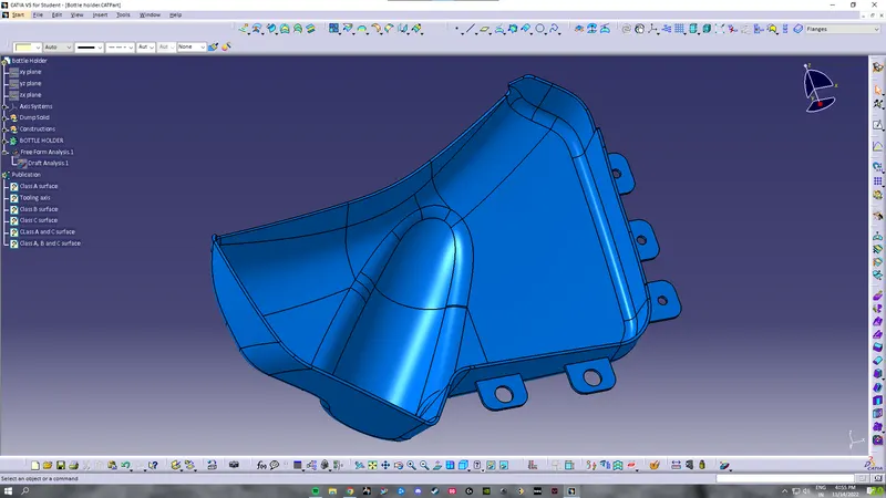
FINAL DRAFT ANALYSIS
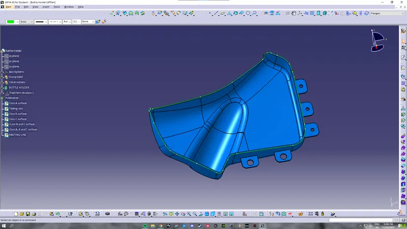
PARTING LINE
C. DOOR LOWER SUBSTRATE
DRAFT
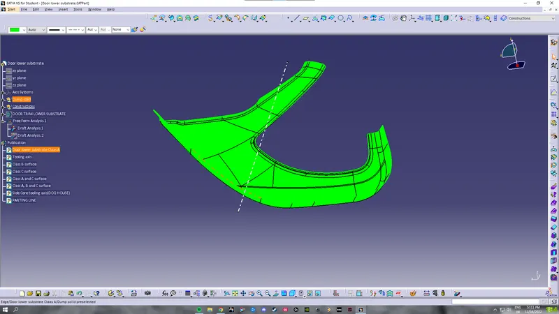
TOOLING AXIS
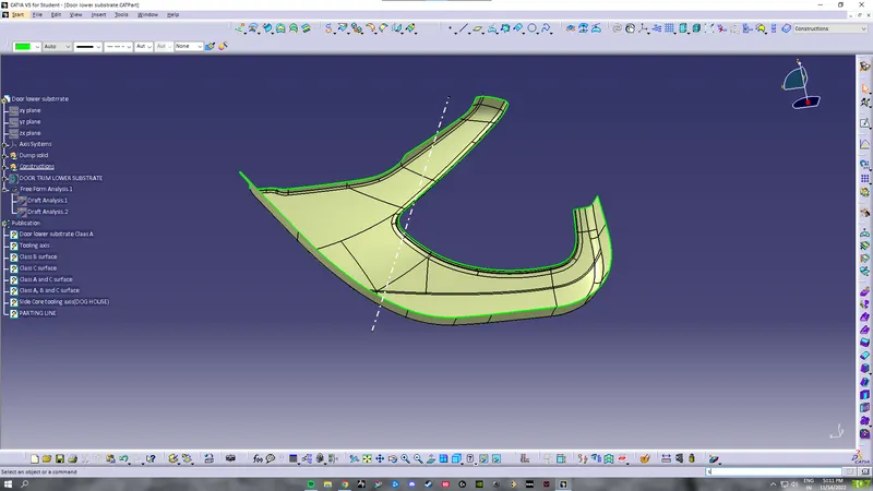
CLASS B SURFACE
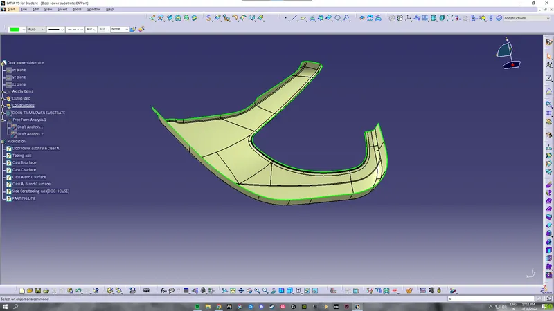
CLASS C SURFACE
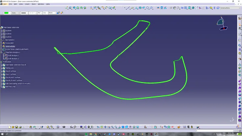
CLASS A AND C SURFACE
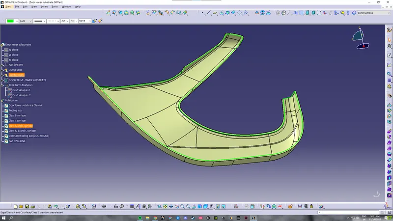
FINAL SOLID
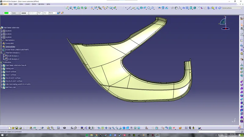
FINAL SOLID WITH B-SIDE FEATURES
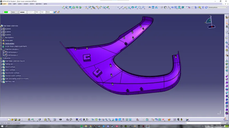
DOG HOUSES
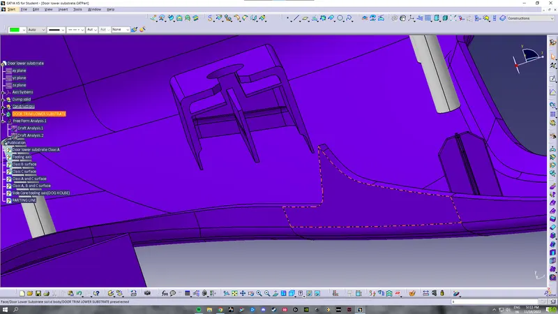
HEAT STAKES
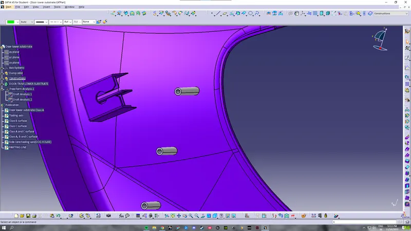
PUSH PINS
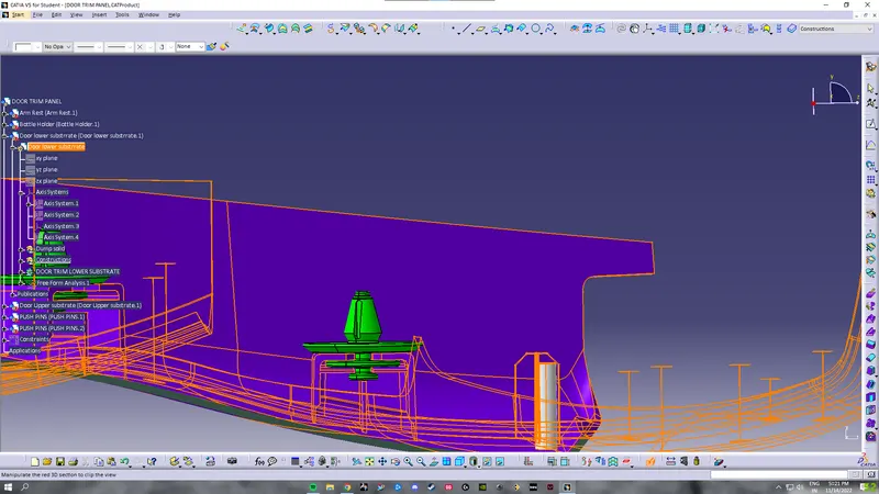
4-WAY LOCATORS
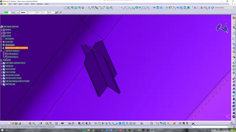
FINAL DRAFT ANALYSIS
Side core tooling axis with draft angle of 0.43
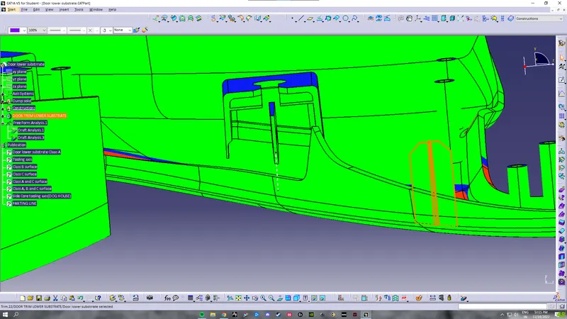
PARTING LINE
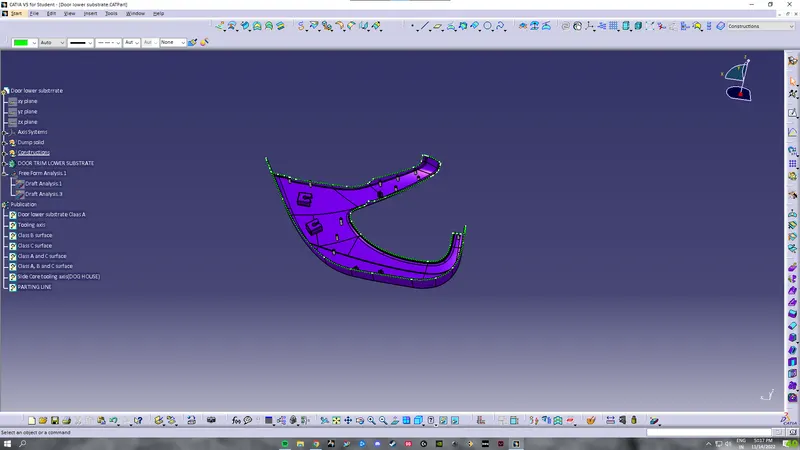
D. DOOR UPPER SUBSTRATE
DRAFT
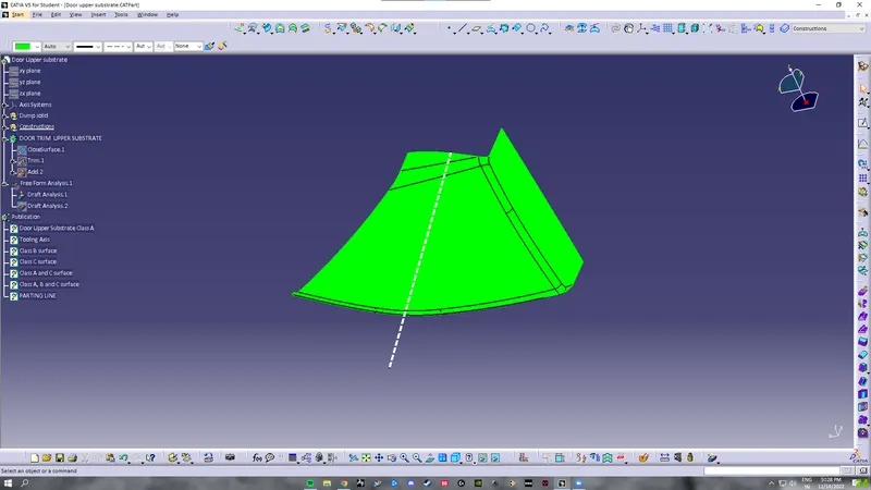
TOOLING AXIS
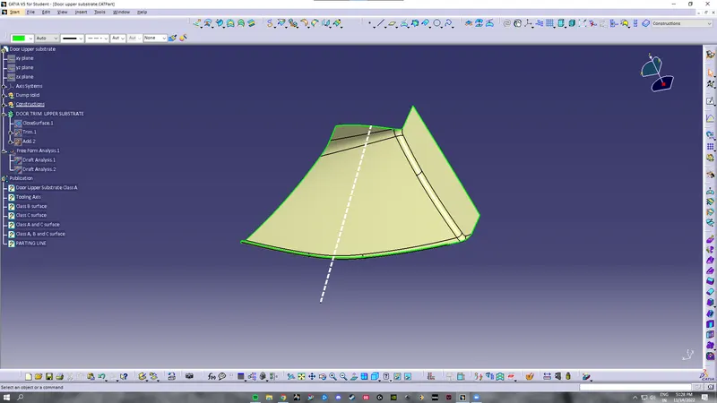
CLASS B SURFACE
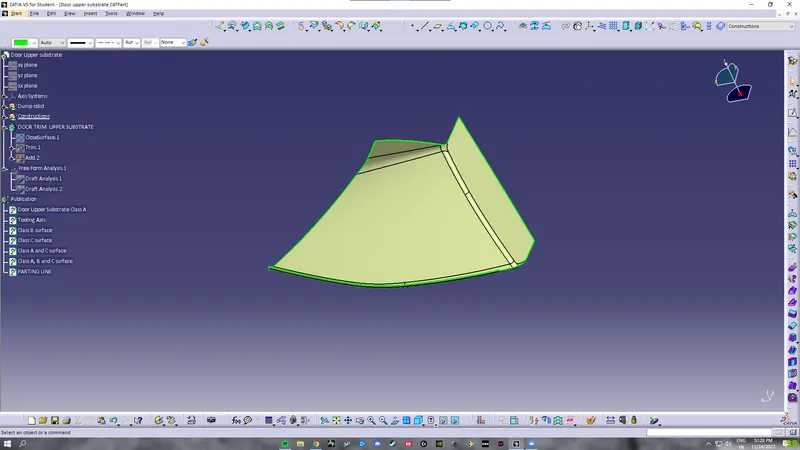
CLASS C SURFACE
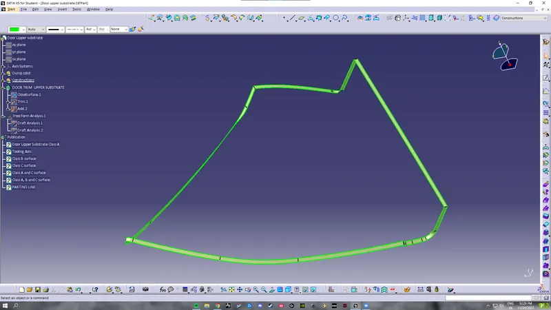
CLASS A AND C SURFACE
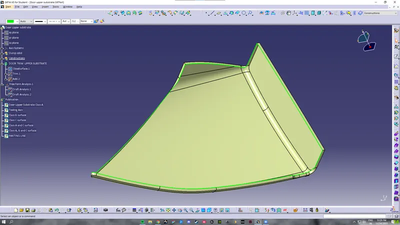
FINAL SOLID
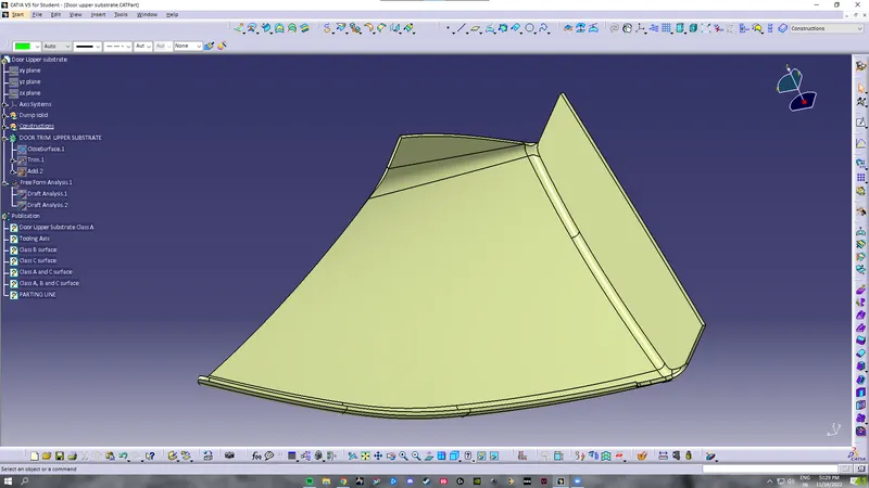
FINAL SOLID WITH FLANGES
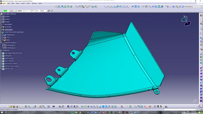
FINAL DRAFT ANALYSIS
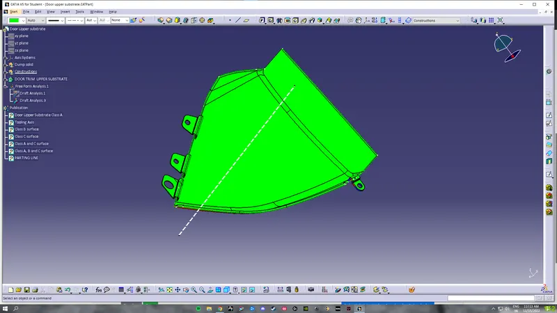
PARTING LINE
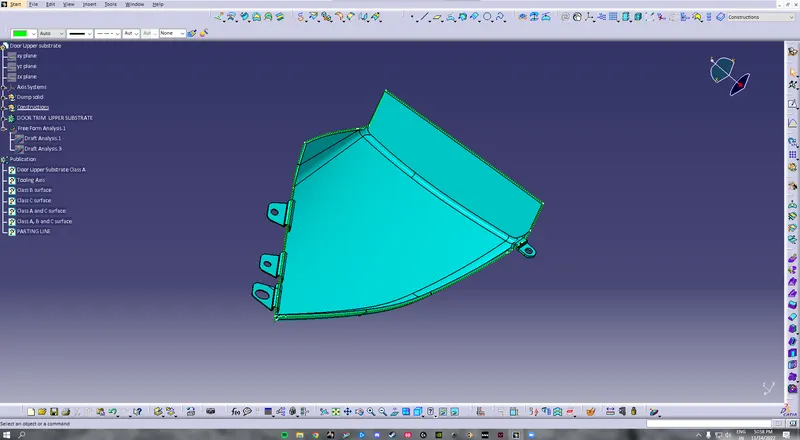
FINAL ASSEMBLY
DIFFERENT VIEWS
ISOMETRIC
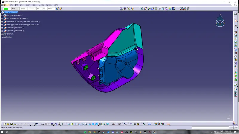
SIDE
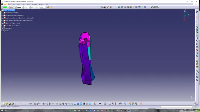
TOP
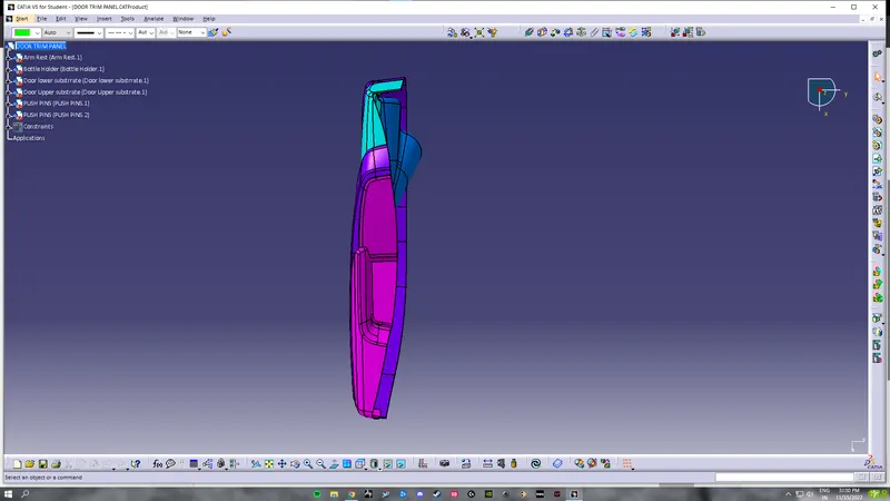
BACK
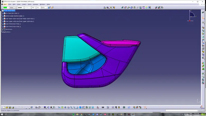
FRONT
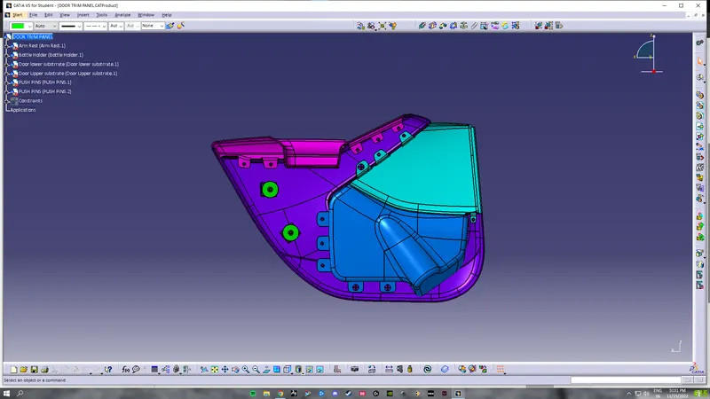
DIFFERENT VIEWS OF ARM REST
ISOMETRIC
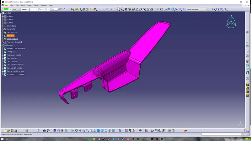
SIDE
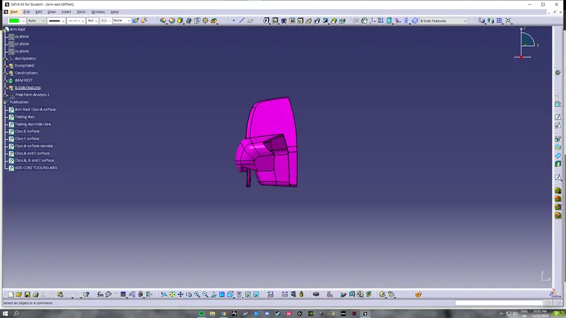
FRONT
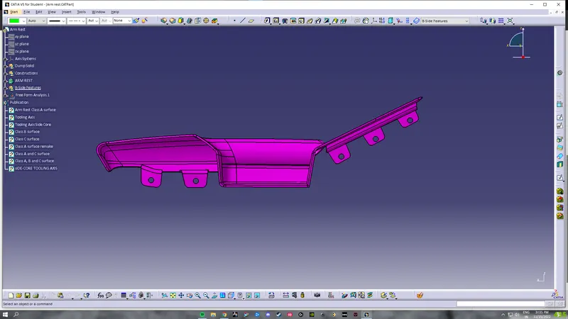
TOP
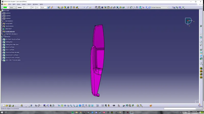
DIFFERENT VIEWS OF BOTTLE HOLDER
ISOMETRIC
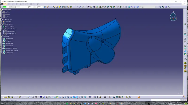
SIDE
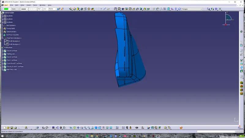
FRONT
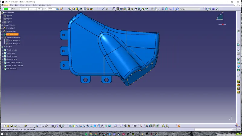
TOP
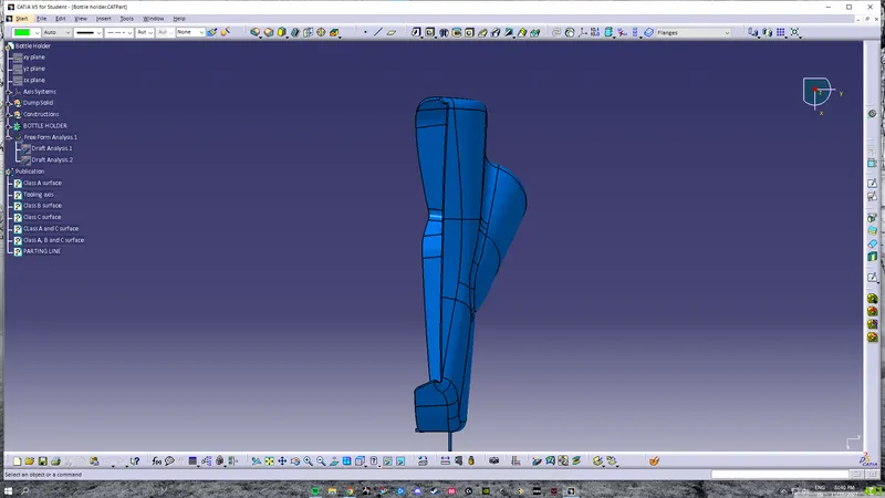
DIFFERENT VIEWS OF DOOR LOWER SUBSTRATE
ISOMETRIC
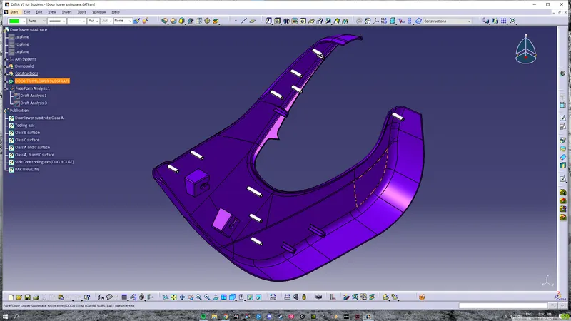
SIDE
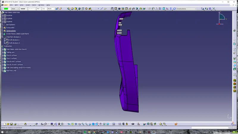
FRONT
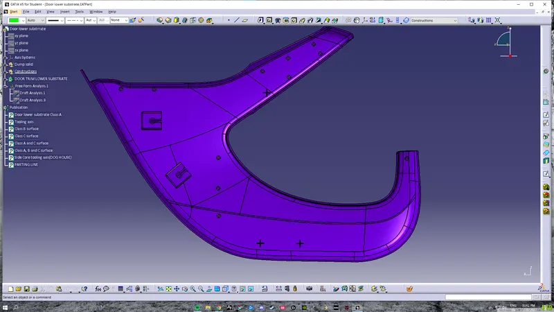
TOP
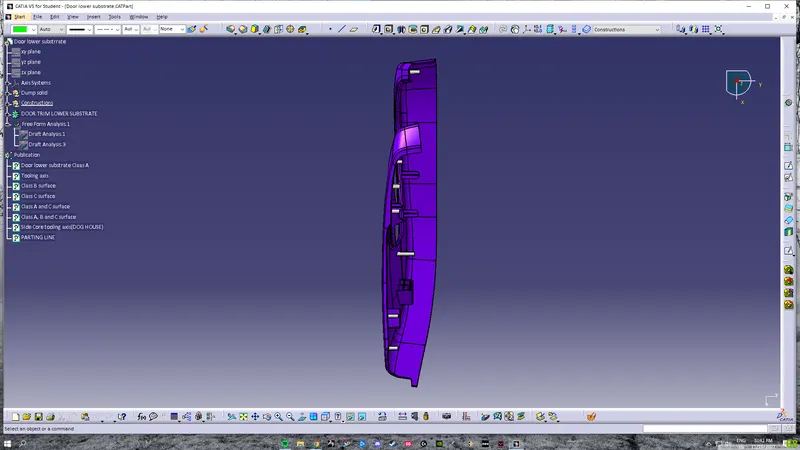
DIFFERENT VIEWS OF DOOR UPPER SUBSTRATE
ISOMETRIC
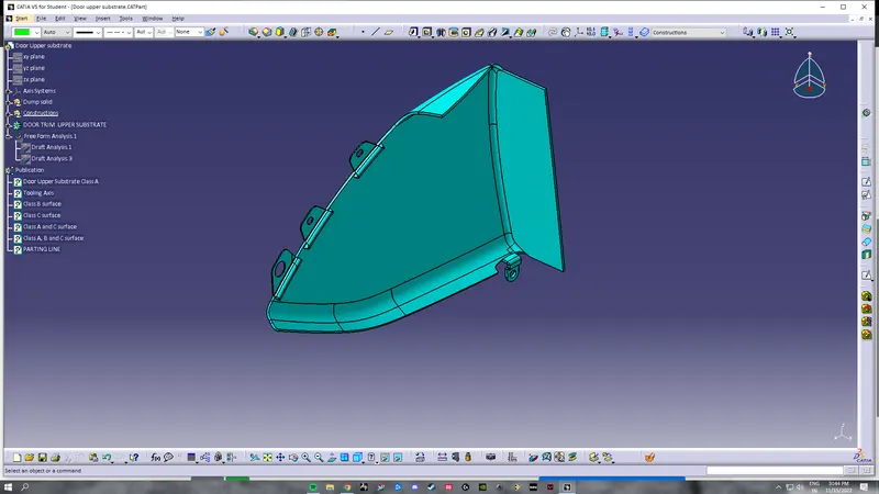
SIDE
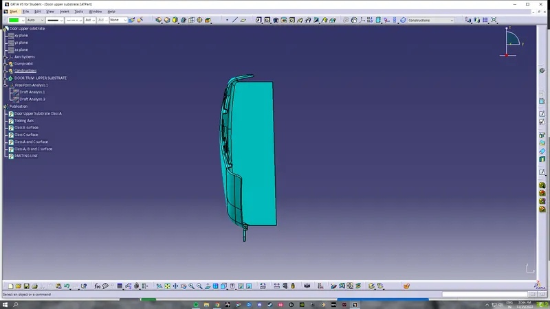
FRONT
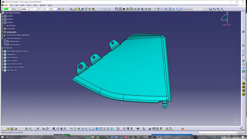
TOP
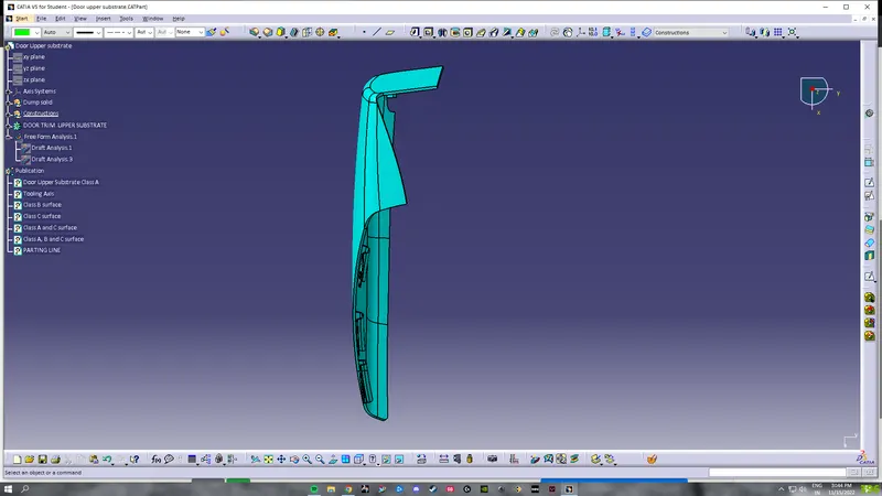
CONCLUSION
Thus the door interior part has been created from the inputs of class A surface along with master section by following the design rules followed in tier 1 and OEM industries in catia v5