Week 11 - Final project
Aim :- Development of a Door Trim panel.Creation of CAD model considering following inputs as like in OEM and tier1 companies
- a) Class A surface
- b) Nominal thickness : Refer master sections
- c) Attachment strategy :
Find a attachment strategy for the door panel complete work.
Use Push pin with Dog house for Lower substrate – Door panel attachment.
Use heat stakes for part to part attachment.
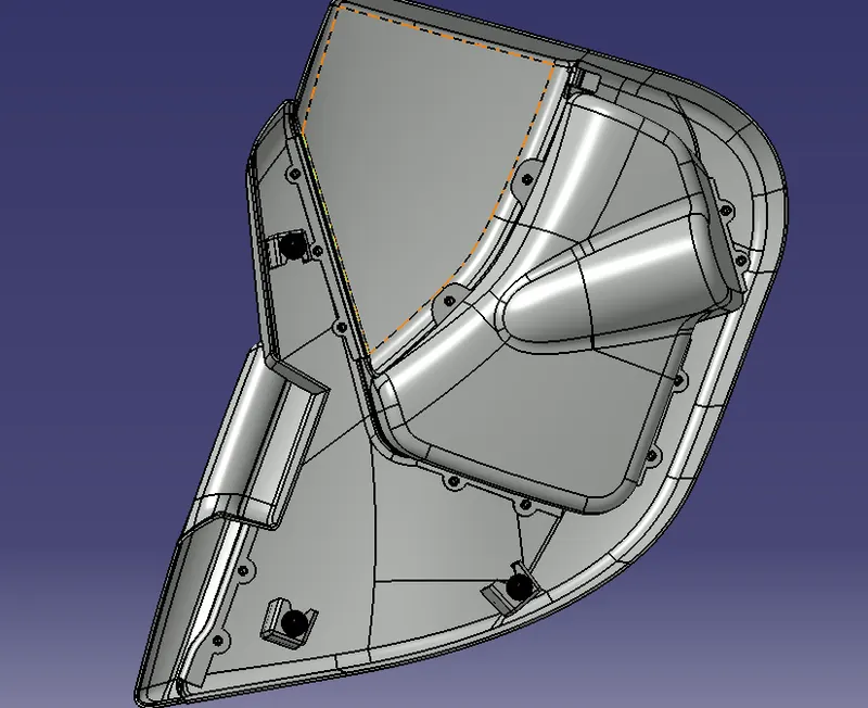
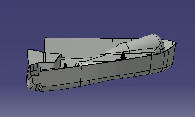
Door trim panel - a Door trim panel is an inner component of a side door of an automobile. it consists of garnish, map pocket , arm-rest , lower substrate. these are visible for the passenger and are finished with proper design aesthetics. the other side of the panel consists of fitments such as heat stakes, push-pins and dog houses.
Given :-
- panel surface -
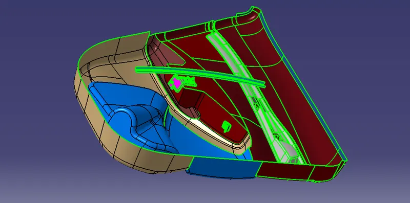
- master sections -
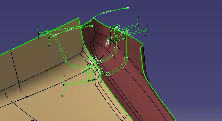
Procedure :-
- The given door trim panel surface is considered as a class-A surface. the master sections are followed for thickening and other feature reference. for the given class-A - class-B&C are created and feature attachments like doghouse, pushpins and heat stakes are placed accordingly.
- Insert separate geometrical-sets for all the individual parts and differentiate them properly. insert separate partbodies for every solid body created.
- Divide the whole class-A into 3 considerable parts which are Arm-rest , Lower substrate and Map-pocket. divide them through creating geometrical sets.
ARM-REST -
given class-A
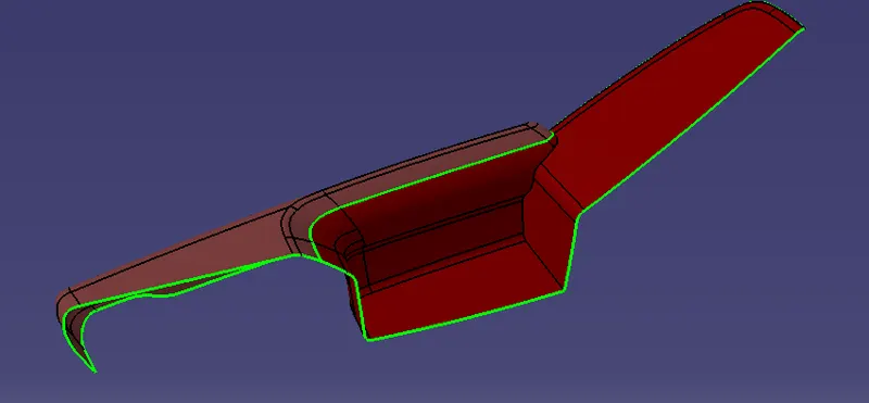
- Divide the arm-rest into two separate parts ie.. the upper part and the bin part through the boundry shown in the picture.
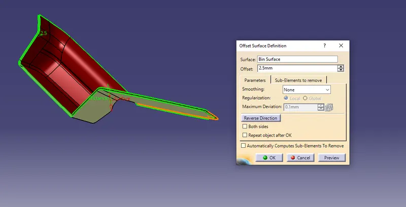
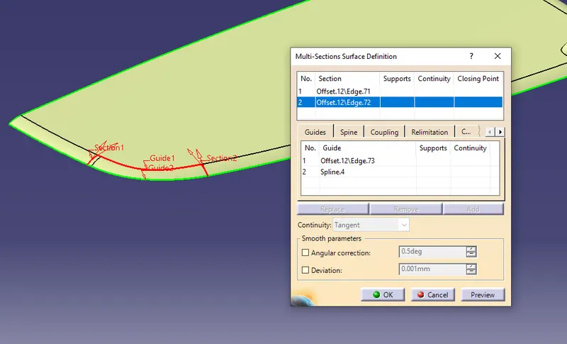
- Consider the Arm-rest bin part initially. hide the other surfaces. extract and offset the whole surface to a 2.5mm (thickness of the component). since some part of the surface are unable to off-set create a spline and use multisections to create the surface and then join
- Now one corner of the surface is improper. create a line at the edges and project it, extrude the surface at the line and split it. use blend option to create the desired surface.
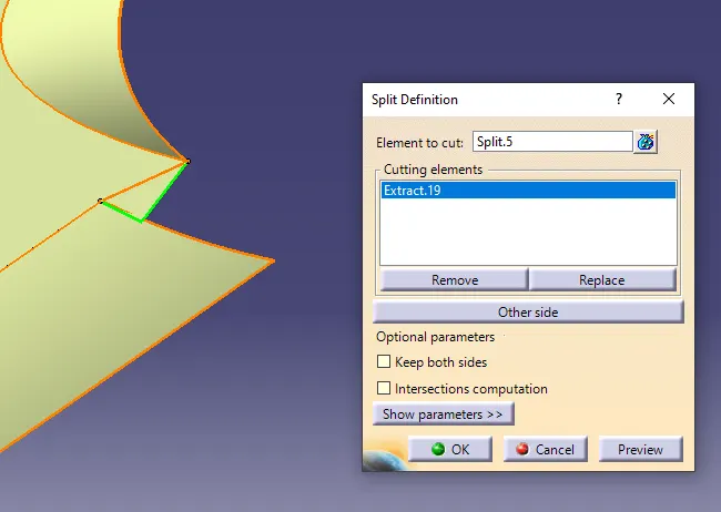
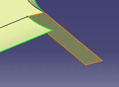
- Now Join the blend surface and the whole surface to get the class-B surface of the arm rest bin part.
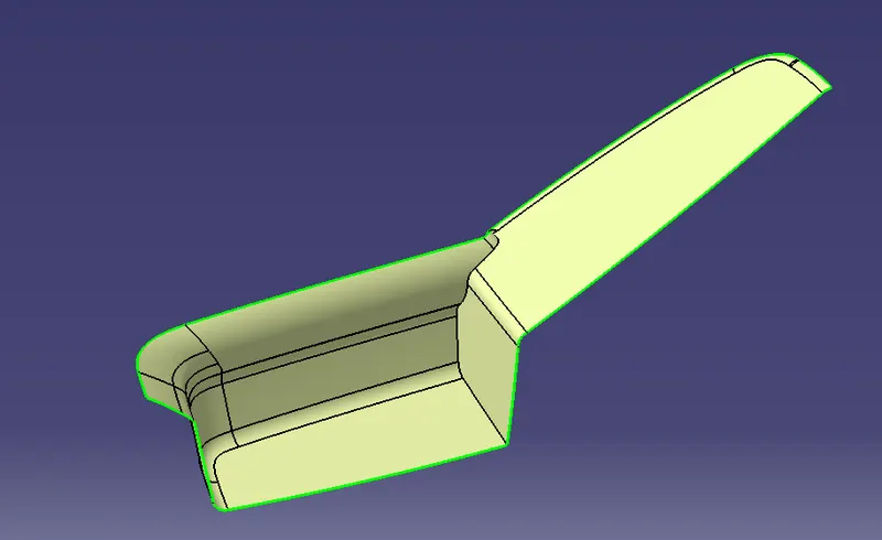
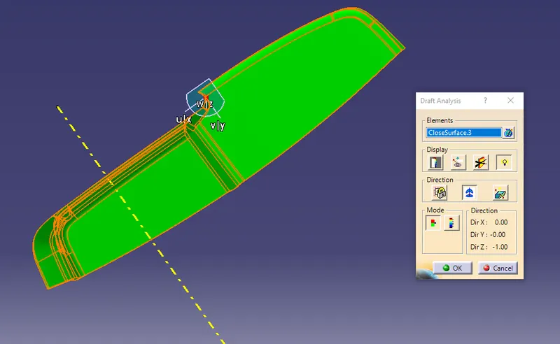
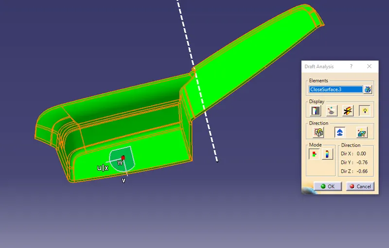
- The Tooling -axis is created using point direction option. create a point on the surface and select the Z-axis as direction and create a line. the slider tooling axis is created according to the draft analysis operation and adjusting the compass. insert separate geometrical-set for tooling axis.
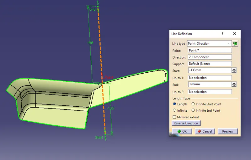
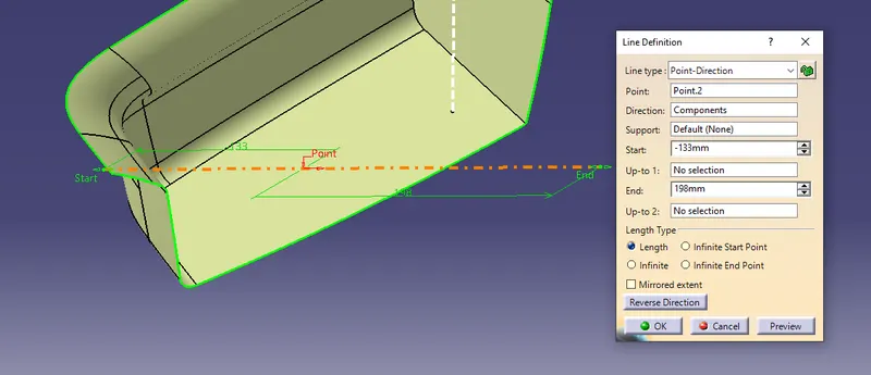
- Now class-C is created using the Class-A as reference. using the boundry extract option with no propogation extract the boundries of the class-A and sweep them through the tooling direction.
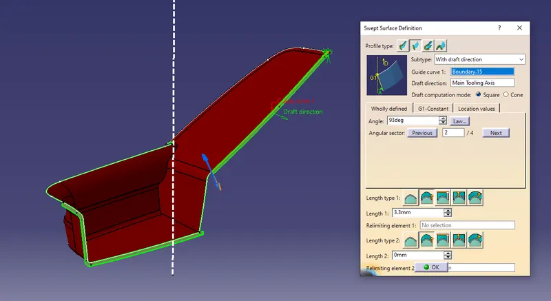
- Create a line and using extrapolate and multi-sections option adjust the c-surface at the inclined portion.
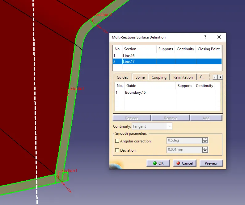
- Similarly on the other side of the surface. use curve-smooth option to aligh the curve with proper propogation . create boundries at the critical part and using sweep and extrapolate option update the class-A and join the surfaces together.
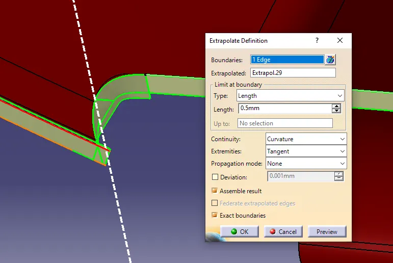
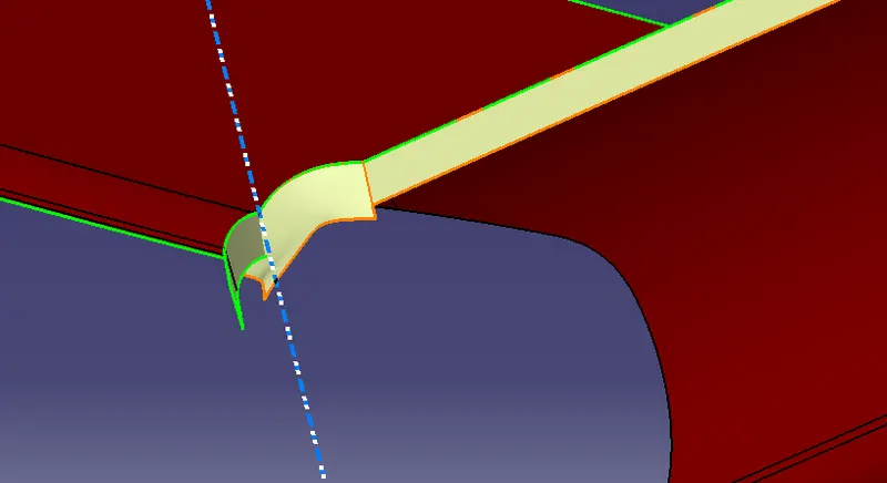
- Trim the sweeped surfaces together and join them with the sweeped surfaces on the other part of the class-A. hance class-C surface is created.
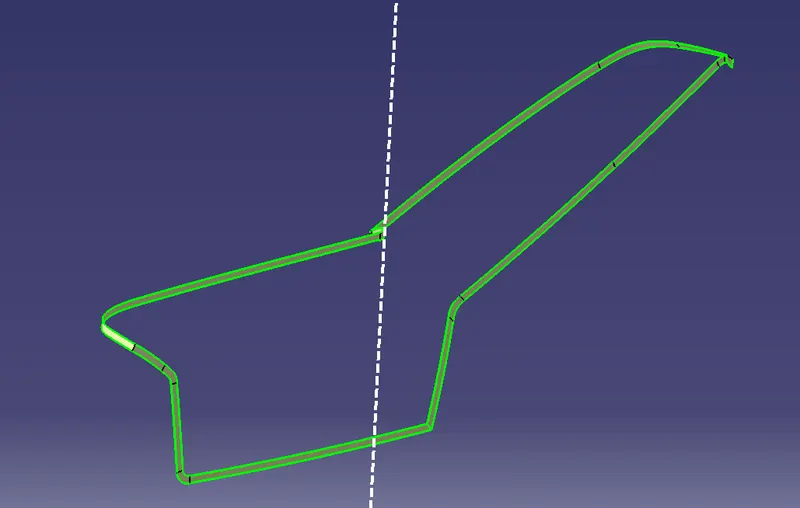
- To join the class-C surface with the updated class-A.. extrapolate the boundries and trim them accordingly. similarly follow the procedure for class-B also and join the three surfaces to create a closed surface. use boundry option from part work bench to ensure the component is closed. hence Arm-rest Bin part is created.
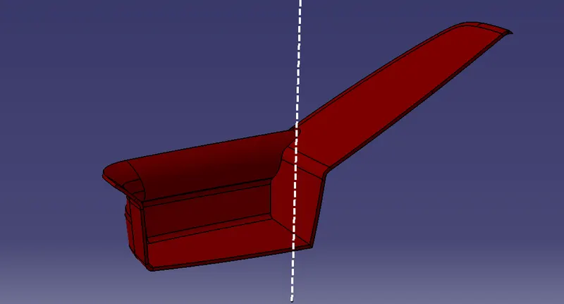
- Insert a part body and rename it for the armrest solid body. use closed surface option to create a solid out of the closed surfaces.
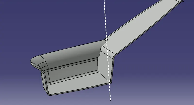
- Now consider the Upper part of the arm-rest. Flanges are created at one edge of the arm-rest. extract the boundries of the class-A and sweep them guide curve. extract the boundry perpendicular to the sweped direction and extrude it. give a 3mm fillet to the edge of the trimmed surfaces.
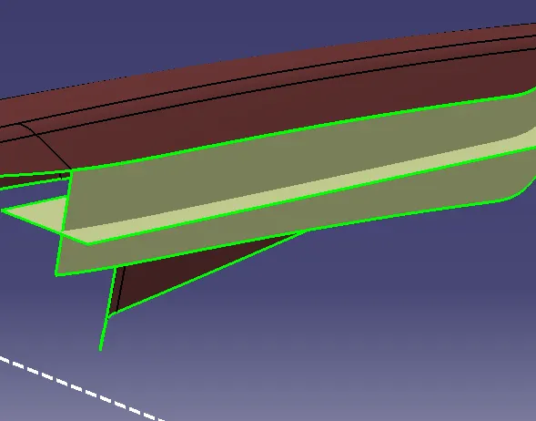
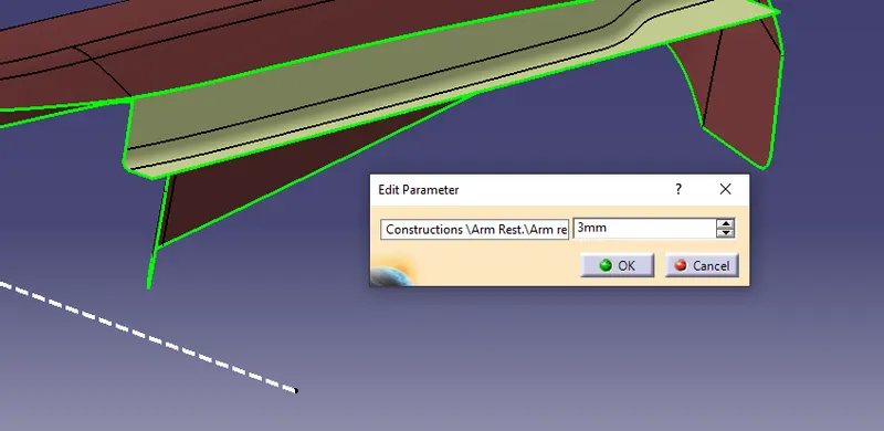
- Extrapolate the surface again and create a plane parallel to the surface with point created as reference.
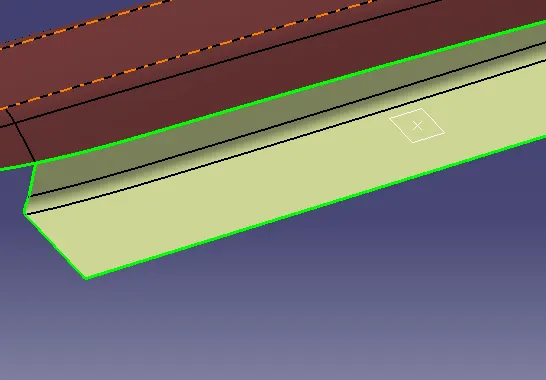
- Create a positioned sketch for the flanges following the design standards through the point and plane as reference and make sure the sketch is iso-constrained. similarly create sketches for the holes in the flanges and split them accordingly to get the flange shape.
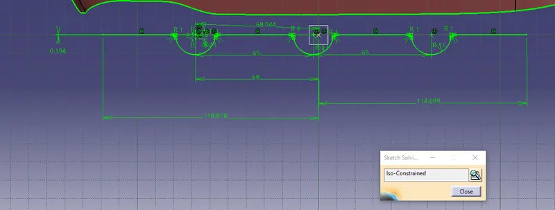
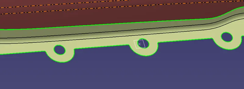
- Extract and Offset the surface to 2.5mm which is the component thickness. similarly using the extrapolate and splitting the surfaces extend the off-set surface in all the directions.
-
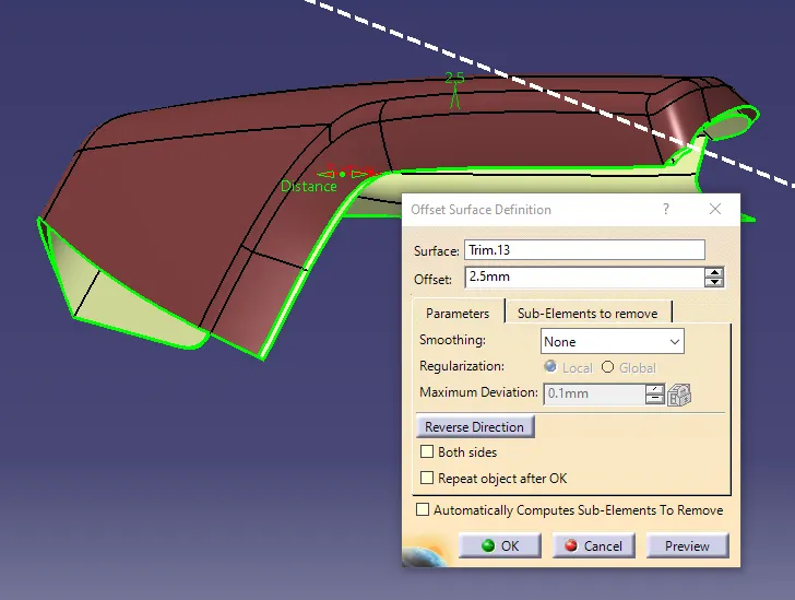
- After extending the surfaces in all the corners. class-B surface is created with flanges. also class-A with flanges is shown.
class-B 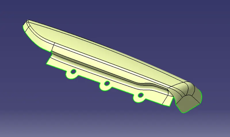 class-A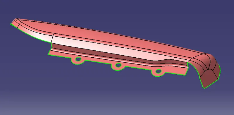
class-A&B with flanges. 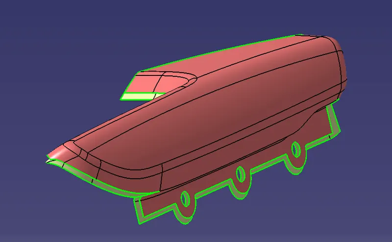
- Now class-C is created through the class-A as reference. using boundry extract option extract the boundries of the class-A surface use smooth curve to properly propogate the boundry line. also use multiple extract option to select them at once.
- Using boundry sweep option with draft direction as main tooling axis sweep the boundry curves towards inside.
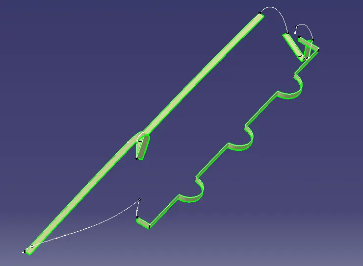
- For the boundries having multiple curves. extract them and using Blend option create a surface accordingly. extract the boundry and using smooth curve and spline option create reference boundry for multisection surface.
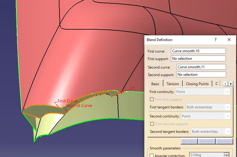
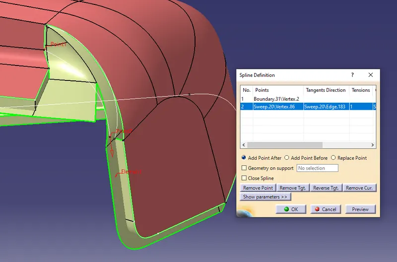
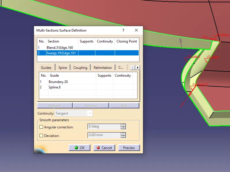
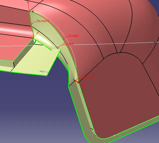
- Trim the newly created surfaces using the above procedure and add them together. similarly extract boundriesof the holes at flanges and using sweep option sweep them using the draft direction.
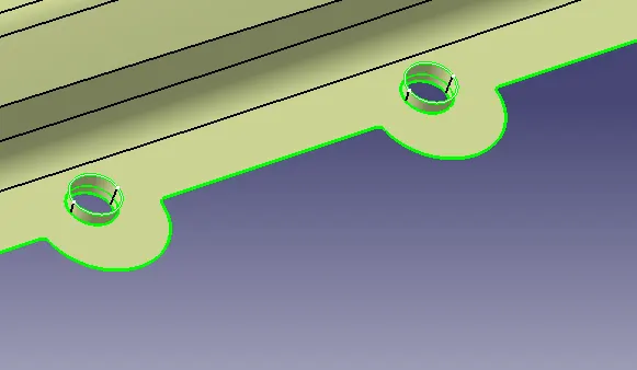
- Join the class-A with the class-C surface created . similarly unhide the class-B and trim it with the class-C surface accordingly. JOIN the class-A,B&C together to form a closed surface. use boundry option to make sure there are no gaps
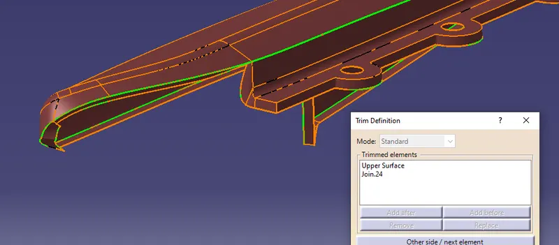
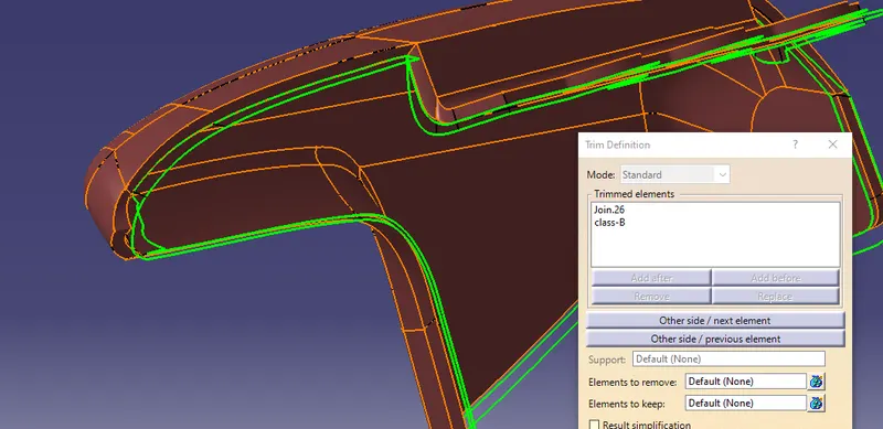
- The tooling axis is created according to the compass adjustment in the desired position during the draft analysis and locking it , then creating a line through the locked axis direction as reference.
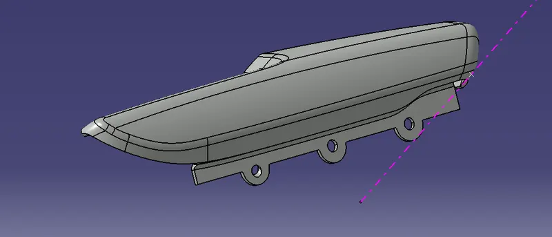
- Insert a part body and through part workbench usning closed surface create a solid .
LOWER SUBSTRATE-
Given class-A
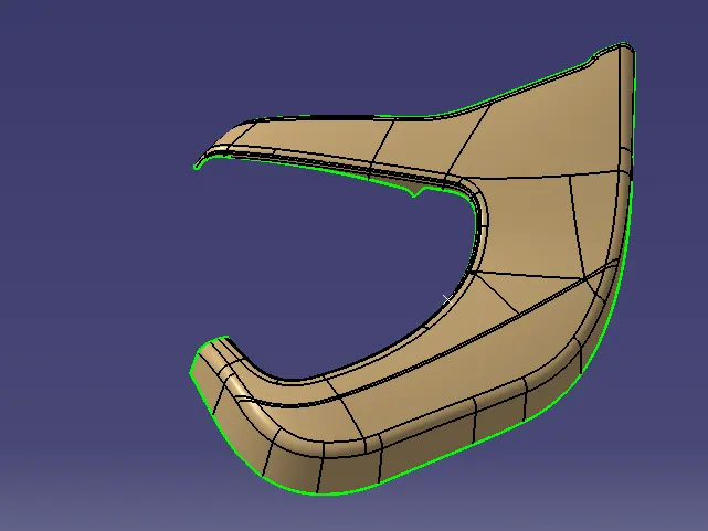
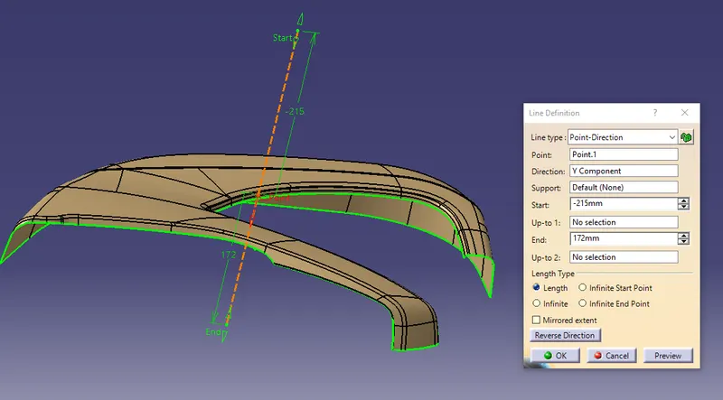
- Insert a geometrical set for the lower substrate as it is a separate component. creating a Tooling axis by creating a line through point direction option in Y-direction.
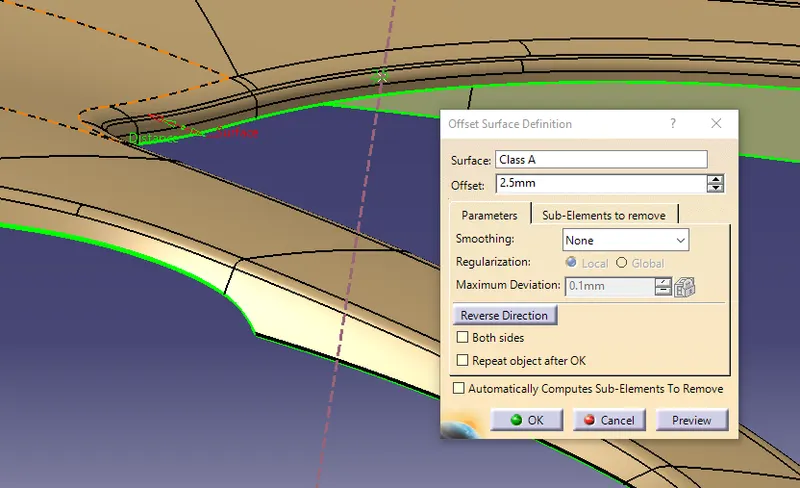
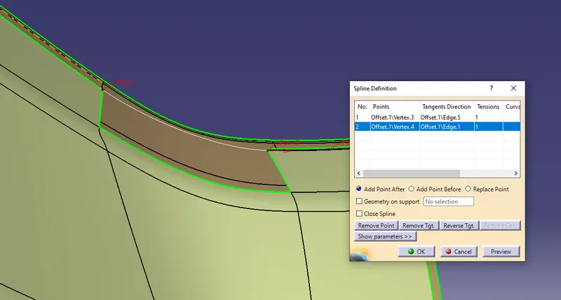
- Now off-set the whole class-A to 2.5mm . since there is a patch of surface that is not formed properly, using spline option create a reference boundry for the surface and through multisection surfaces fill the patch and join them with the off-set surface.
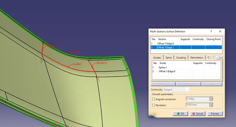
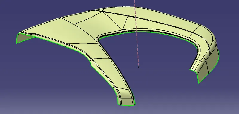
- Now extract the boundries using the tangent propogation method and extrapolate the surface to 0.7mm to align with the class-A surface.henc a class-B surface is created.
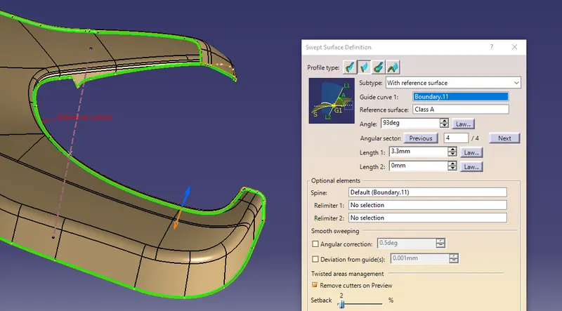
- Similarly extract the boundries of the class-A using tangent propogation method and sweep the boundry through reference surface. at the boundries with multiple curves use multi extract and curve smooth the boundry then using multi section surfaces create the C- surface.
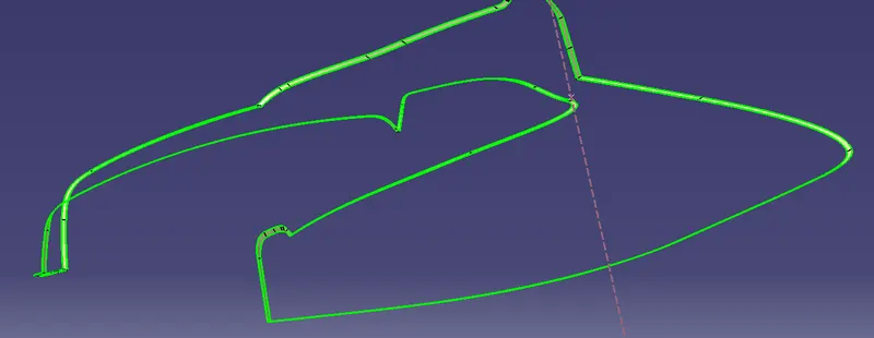
class-A with class-C surface - 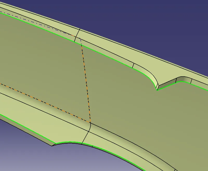
- Now trim class-A&C surfaces with class-B surface to get the final trim closed surfaces. use boundry option to check for any gaps in the closed surfaces.
- Insert a part body and through part work bench create a solid out of the surfaces created.
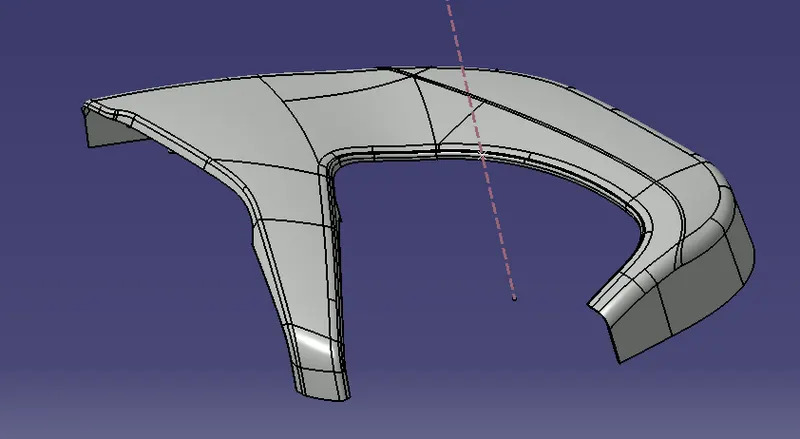
MAP POCKET -
- The map pocket is divided into two parts ie.. upper and lower
Upper part-
- Given class-A surface. create a point on the surface and using point-direction option and Y-axis create a line through the point , extend the line sufficiently. consider it as tooling axis for the upper part of the map pocket.
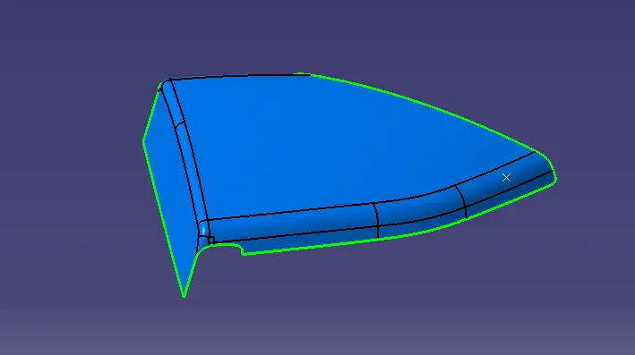
- Since the upper part required modifications additionally to fix with the fitment/ features. flanges are created. similarly with the upper part of the arm-rest. extract the boundries and use curve smooth to get a uniform boundry extraction. using sweep option and 90 degrees create the surface accordingly. use the sweep option with draft direction.
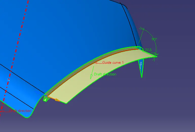
- Now create a positioned sketch through the point and plane created on the sweeped surface as reference. follow the similar guidelines for the flange sketch creation. make sure the sketch is iso-constrained.
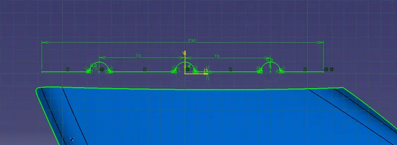
- Now split the surface created with the flange sketch and also create holes for the flanges through positioned sketch .
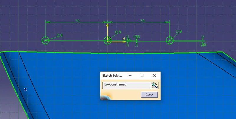
- Similarly split the surface with the flange holes.
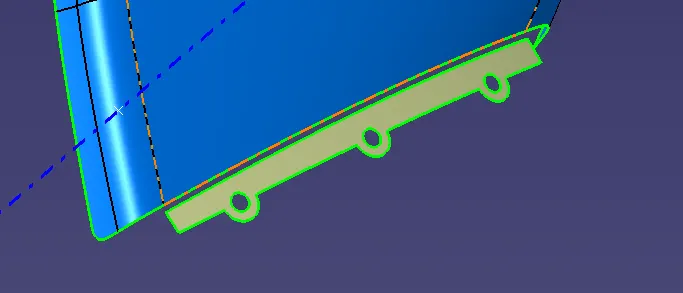
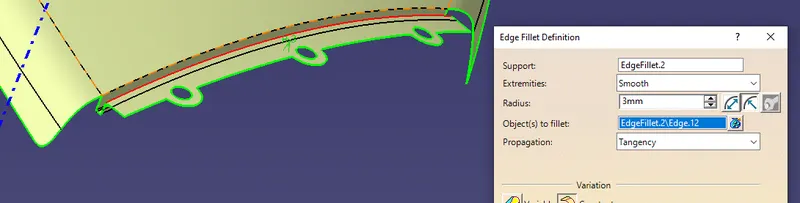
- Join the flange surface with the class-A surface and add 3mm edge fillets to make a improved class-A surface.
- Now to create class-B surface using the improved class-A. off-set the entire surface to 2.5mm.
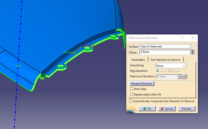
- Since the off-set surface contains missing patches near the corners they are cleared by using the boundry extract and filling the area with multisection surfaces . extrapolate the patch surface accordingly and split them with the desired surfaces. make sure the procedure is followed by comparing with the improved class-A surface as reference.
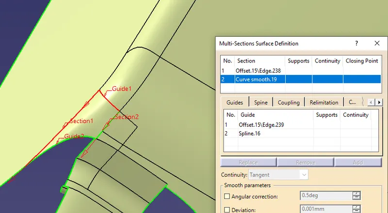
- After creating the surfaces split and join them accordingly to get the final class-B surface.
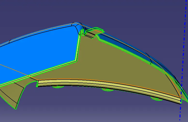
- Now class-C surface is created using the class-A improved as reference. extract the boundries of the surface individually and using curve smooth clear the boundry curve. sweep the extracted boundries using the draft direction .
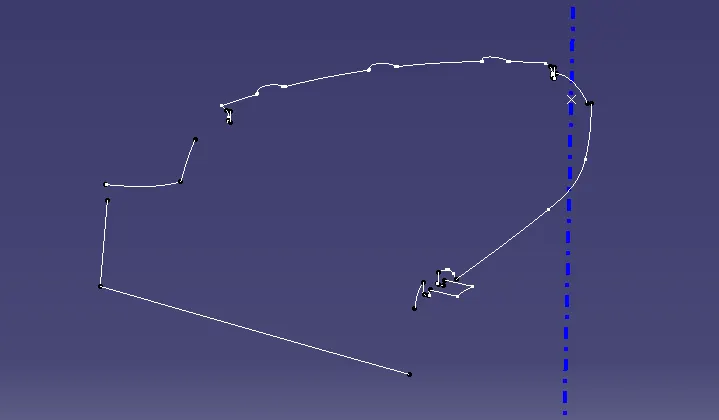
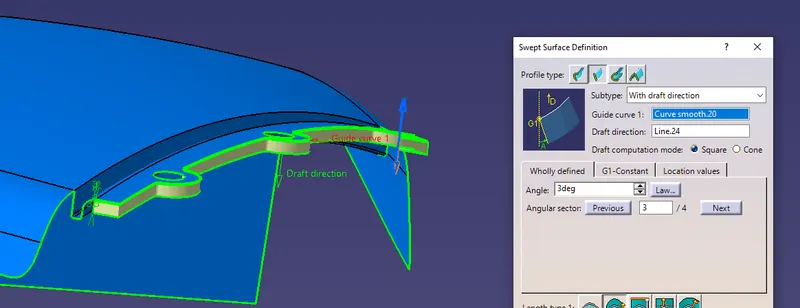
- Since some of the curved parts are complicated to get the sweep surface. using extract option get the boundries individually and use multisection to create the surface.
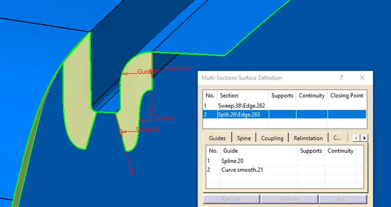
- Similarly follow the procedure to create the class-C surface.
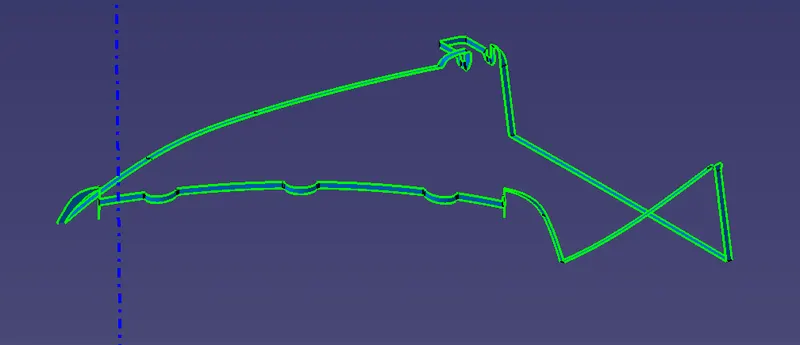
- Join the class-C surface with the class-A surface.
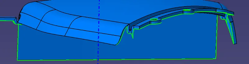
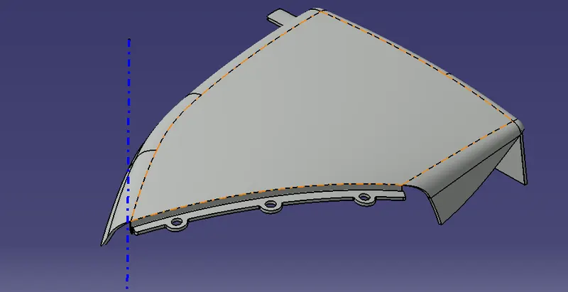
- Join the class-B surface with the class-A and C. extrapolate and trim the surfaces to join them perfectly. use boundry option to make sure the surfaces joined are closed surfaces.
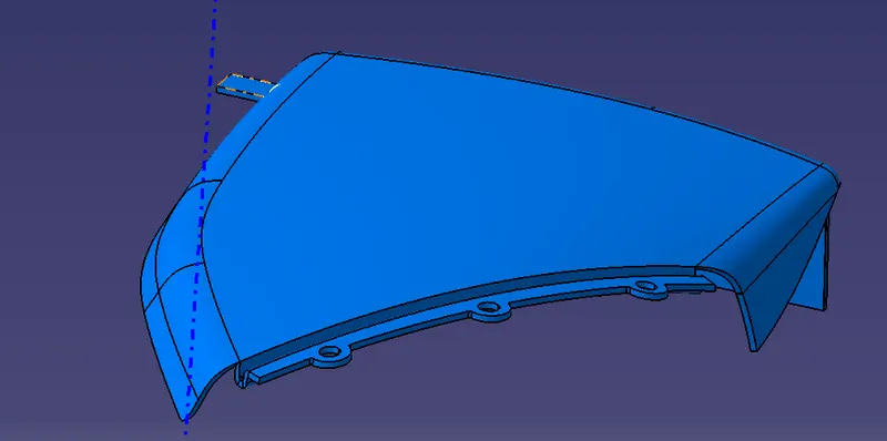
- Now insert a part body and Goto part design and using the closed surface option create a solid body out of it. add 2mm edge fillets at the required edges.
Lower part -
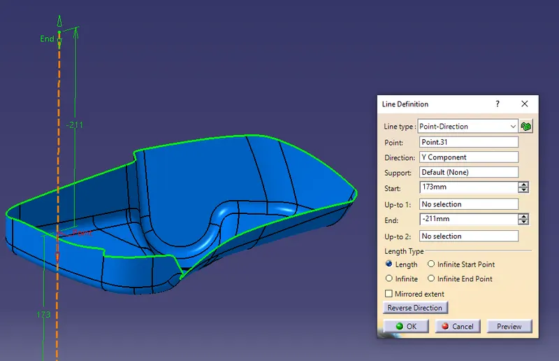
- Create a point on surface and a line using the point direction option in Y-axis. consider it as tooling axis. given class-A
- Flanges are created for the lower part similar to the upper part of the map pocket. extract the boundries of the class-A surface and using sweep option create the flange surface.
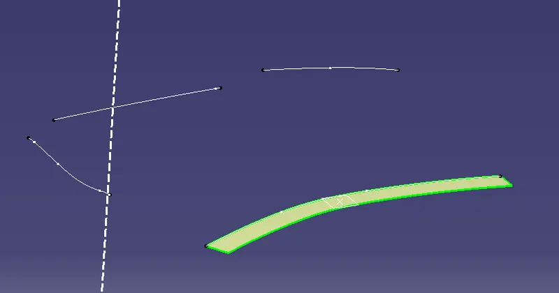
- Create a positioned sketch for the flange shape and make sure the sketch is iso-constrained. split the sketch with the surface.
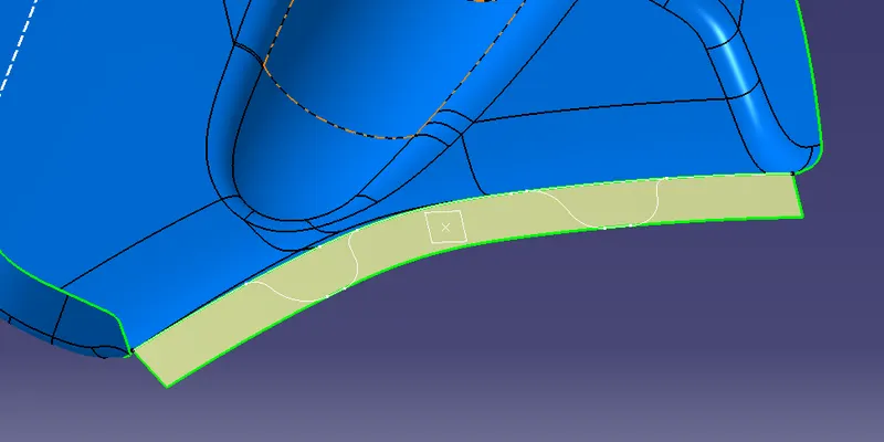
- Similarly follow the procedure to create flange surfaces on the other side of the part also. create holes using the sketch on the plane and use extrude option and trim the holes.
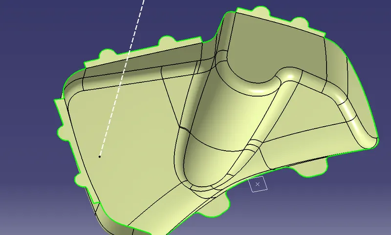
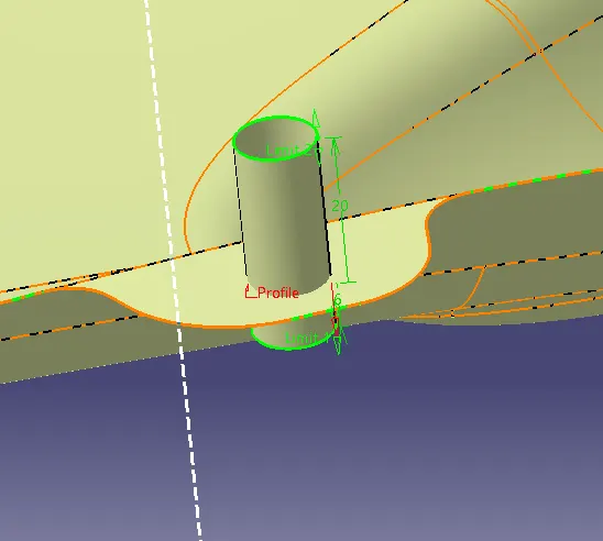
- After flanges are added the class-A surface is updated accordingly.
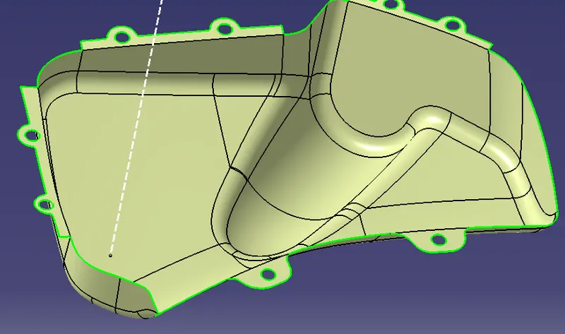
- Now class-B surface is created using the off-set 2.5mm . extrapolate the surfaces near the flange area to extend the surface accordingly.
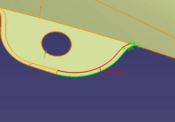
- Class-B surface is created .. the corners having curves are filled using boundry extract and multi section surfaces.
- Now the class-C surface is created by using the improved class-A as reference. using multiple extract option extract the boundries of the class-A.
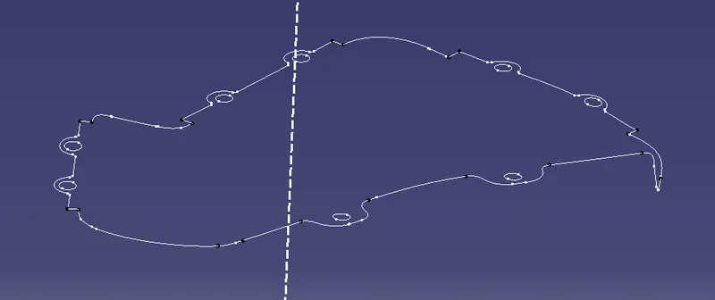
- Using Sweep option create surfaces through the boundries extracted. since the corners with complicated curves cannot be sweeped. using multisection surfaces create the complex surfaces and join them. extrapolate and trim to get the required shape of the surface filling
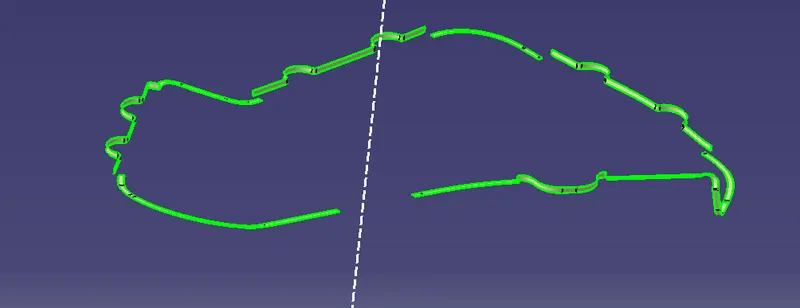
- Sweep the sketch created for the holes in the flanges. trim them accordingly. now join the class-C surface with the class-A improved surface to remove the boundry between them.
- Now extrapolate the class-B surface at the corners to intersect with the class-C surface and trim them together . use fill or multisection option to add the missing patches of the surface near the class-C surface.
- Using the boundry option make sure the surfaces are closed together.
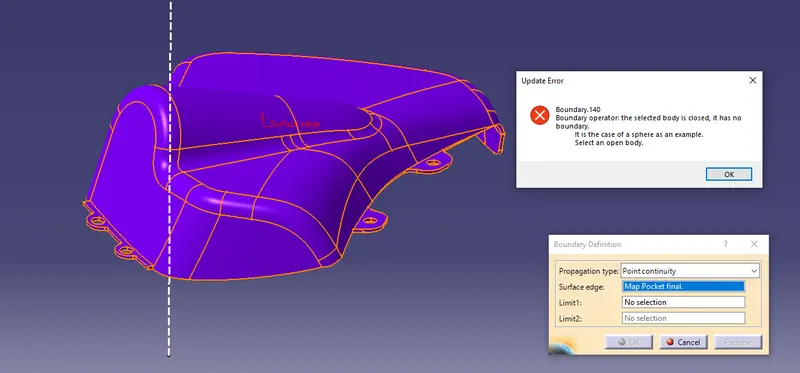
- Insert a part body and create a solid out of them using the closed surface option in part design.use 0.5 and 2mm edge fillets at the required places.
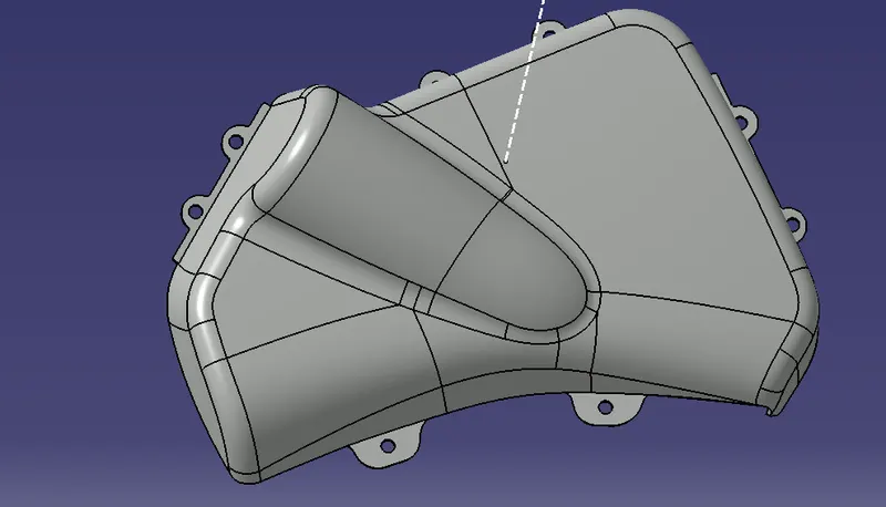
B- SIDE FEATURES :-
HEAT STAKES-
- Whenever two or more components need to be attached to one another, and at least one is made of a thermoplastic, a combination of heat and pressure can be used to reform the plastic to the many shapes or profiles to retain or join the parts together.
- Unhide the components and on the class-B side create points over the flange circles and extract the boundries of the holes. using the extrude option create heat stakes.
- Using thicken surface with 1.25mm thicken create solid heat stakes. now translate the solid heat stakes to the other location through copy- paste specials option and translate through point - point method.
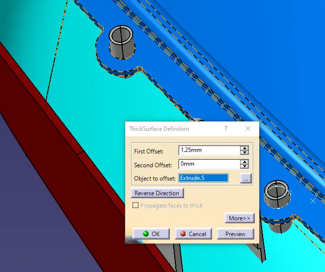
- Using Boolean operation unionTrim them to the required parts..
DOG HOUSE -
- Dog house is an engineering feature used in plastic trim design. dog houses are used as supporting feature. ...they are subjected to draft analysis to prevent breakage of the component during ejection from mould cavity.dog house and other engineering components are built on B-surface.
- Create a sketch at the required position on the B-surface. the positioned sketch must be according to the dog house design rules and the sketch must be iso-constrained
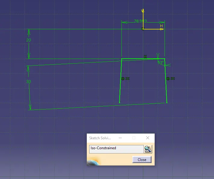
- Extrude the sketch in the tooling direction and off-set the lower surface to the 50mm according to the height of dog house.
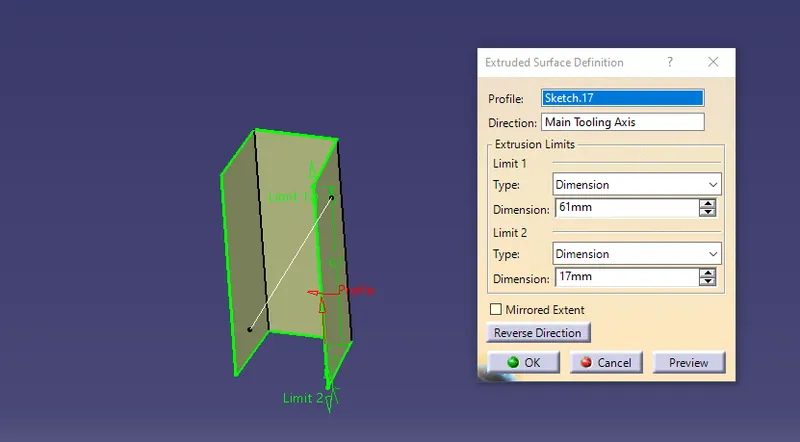
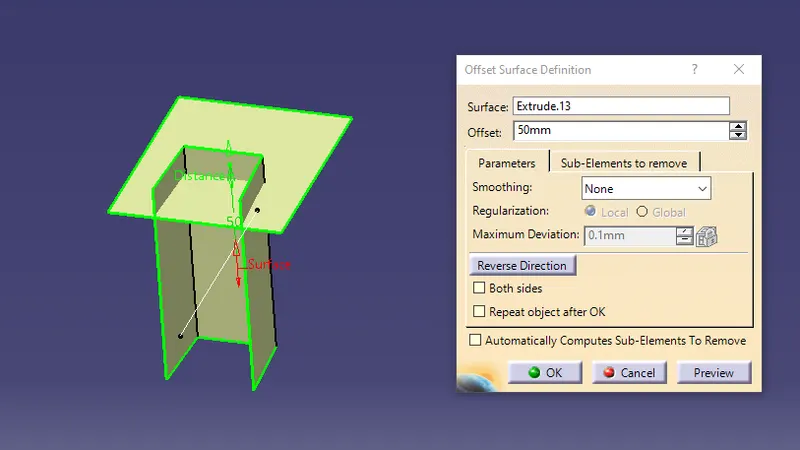
- Now extract the lower surface which is uneven in surface and off-set it 6mm and trim it accordingly.
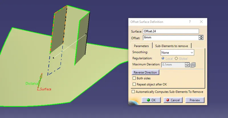
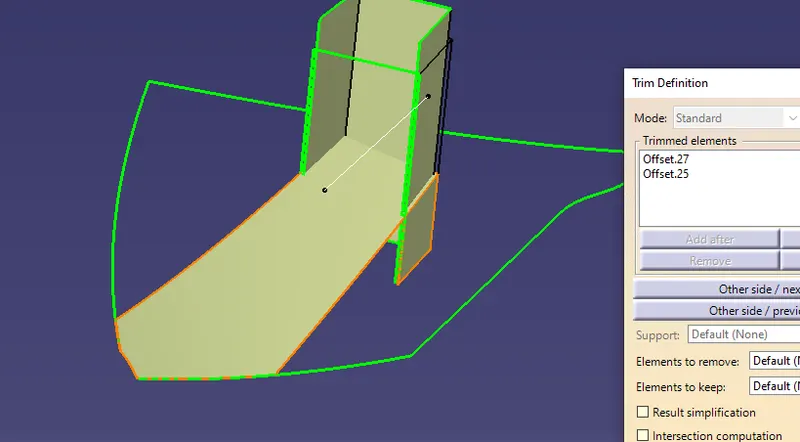
- Insert a part body and thicken the surfce of the dog house with 2.5m . split the inner lower part outwards. and add draft angle 0.5 degrees
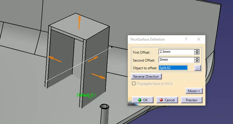
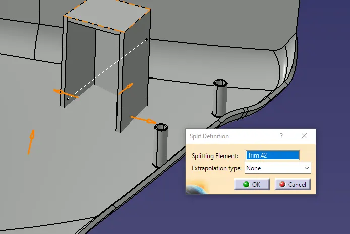
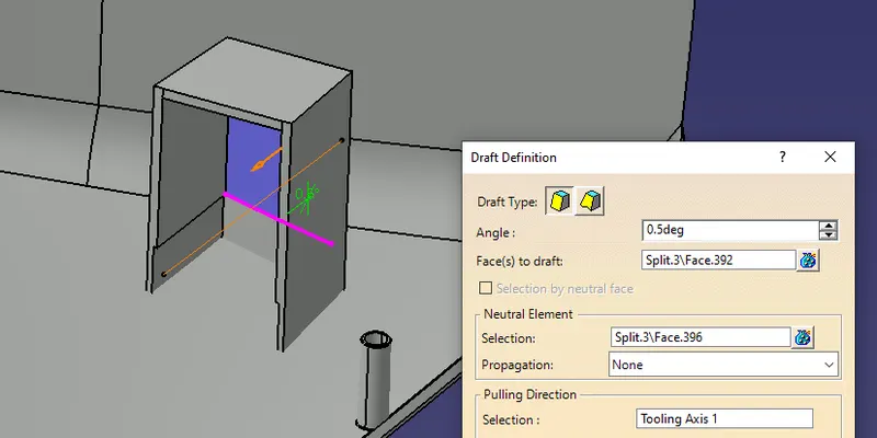
- Create a sketch for the pocket at the require4d location and create a pocket space for pushpin accomodation. also give draft angle to it with 0.3mm edge fiullets.
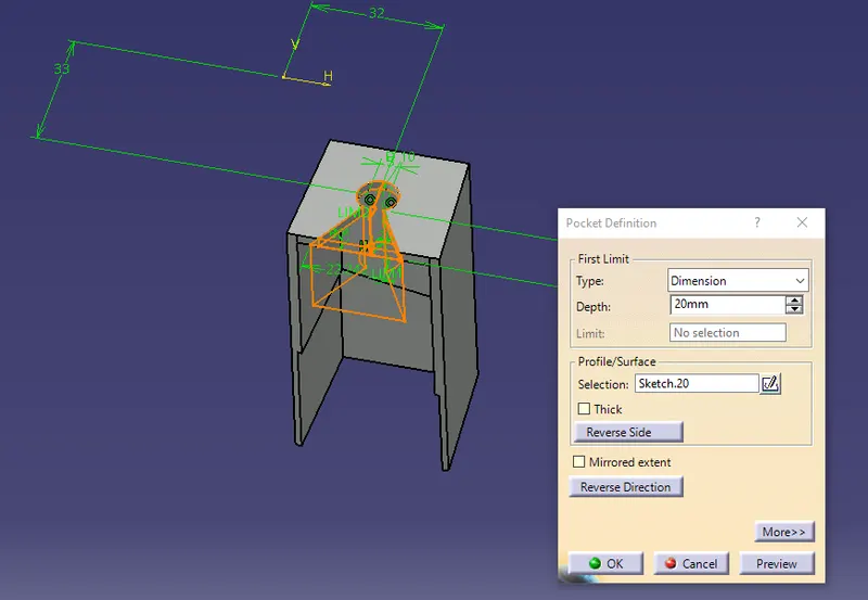
- Similarly perform the same procedure to create other dog houses at different locations. assemble all the part bodies under one part body and UNIONTRIM them to the Lower substrate.
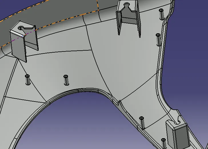
- PUSH PINS are created with the dog houses. create a positioned sketch with plane as reference following the push pin design rules and make sure the sketch is iso-constrained.
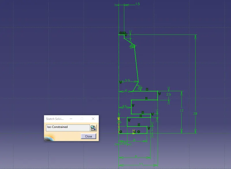
- Use shaft option to create the solid out of the sketch . give chamfer of 1mm with 75 degrees angle.add edge fillets with minimum radius.
- Create a positioned sketch for the pocket on the pushpin.
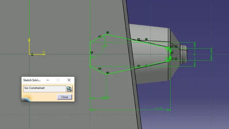
- Use translate option to move the pushpin in co-ordinate directions to adjust on the dog house. similarly translate the part body using copy-paste specials procedure and translating the pushpin solid body using point to point option.
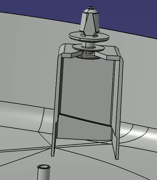
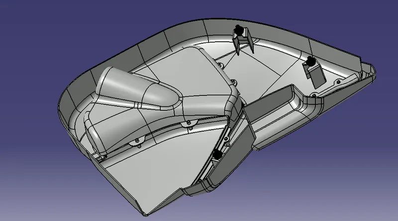
- Unhide all the solid bodies created . use publish option to highlight the components from the model tree.
DRAFT ANALYSIS :-
- Draft angles are very important in thermoforming product design. If the product is formed onto a female or negative mold, it shrinks away from the mold sidewalls. As a result, true female or negative products can be thermoformed with vertical walls having zero draft angles.
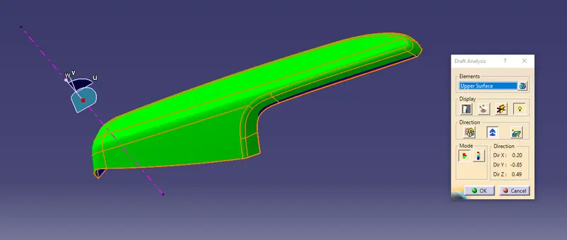
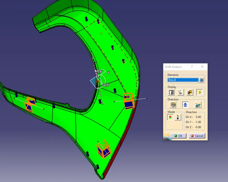
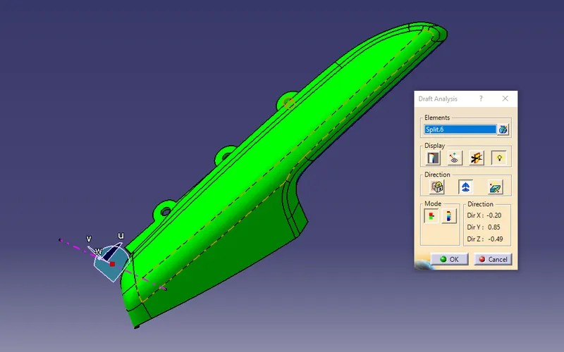
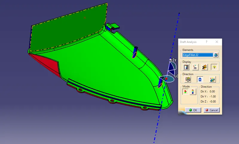
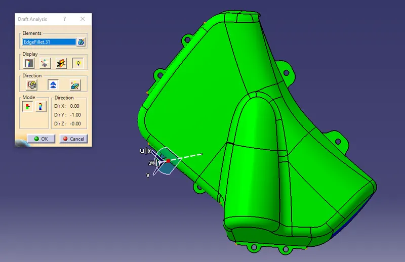
- In generative shape design Goto- insert- Analysis- Feature Draft analysis and select the component, place the compass over the tooling axis and adjust the pointer to visualise the draft angle.
Class-A
Arm-rest upper -
Arm-rest bin part -
Main tooling axis 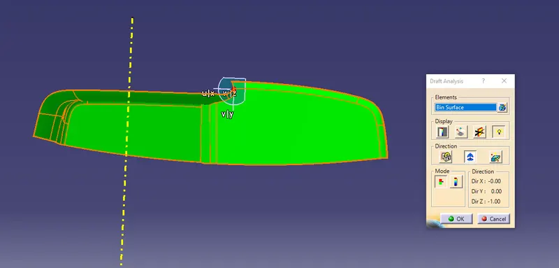
Slider tooling axis 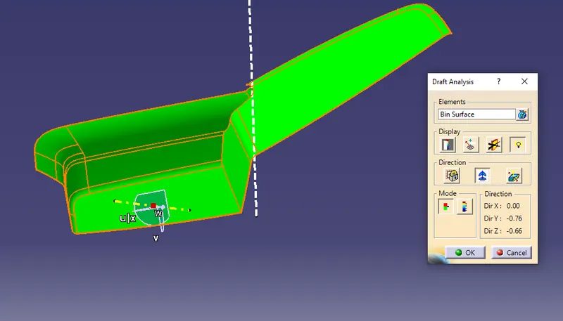
Map pocket-
lower 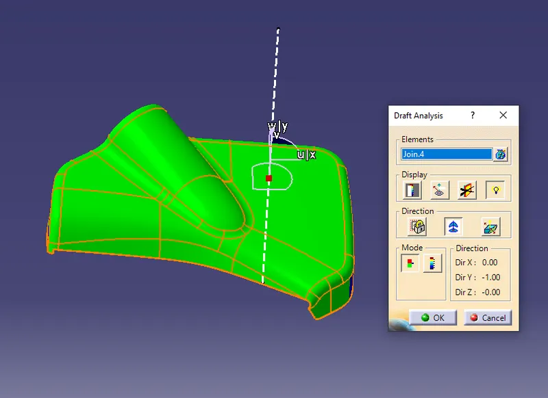
upper 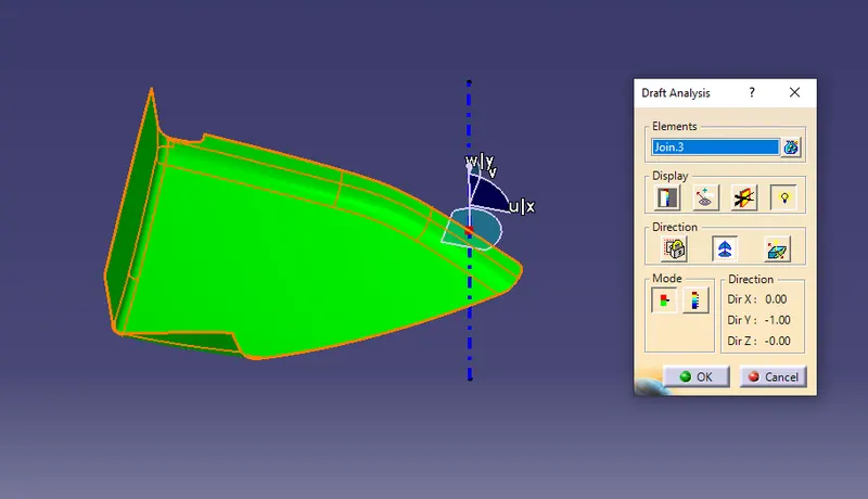
Lower substrate-
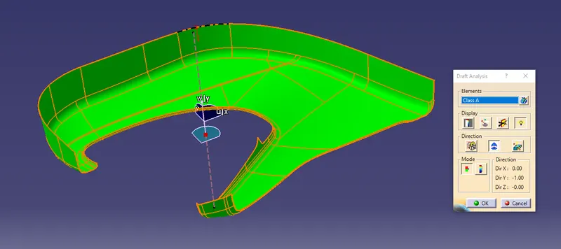
SOLIDS :-
- Armrest-1
- Lower substrate
- Arm-rest 2
- Map pocket-upper
- Map pocket-lower
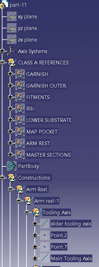
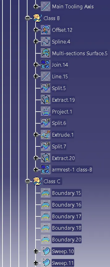
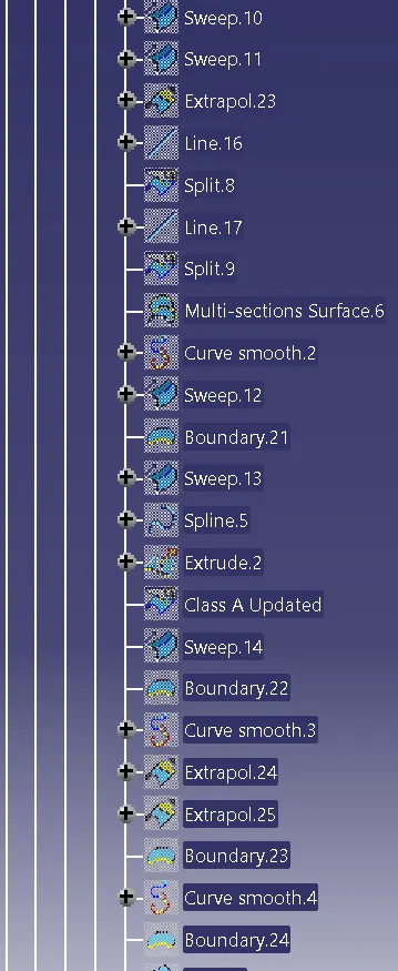
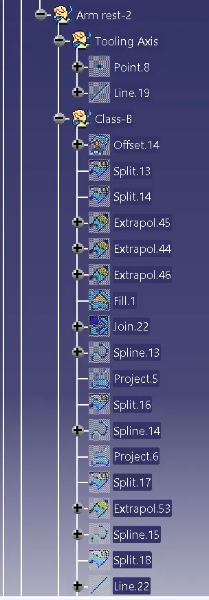
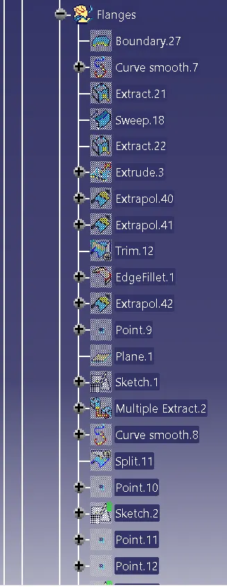
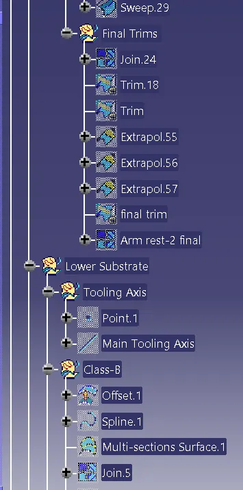
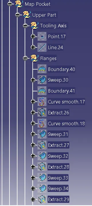
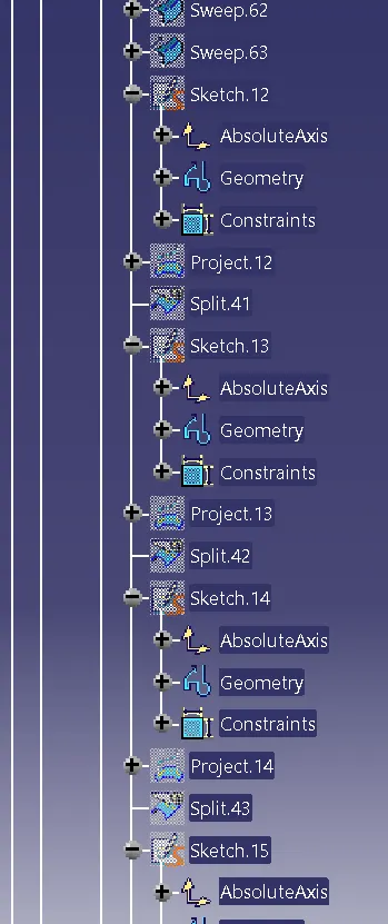
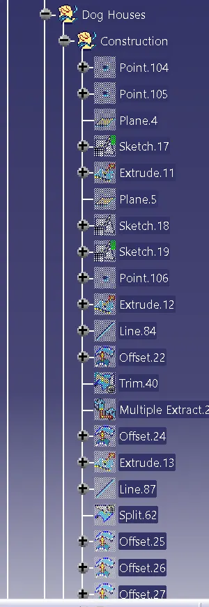
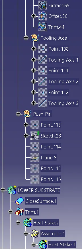
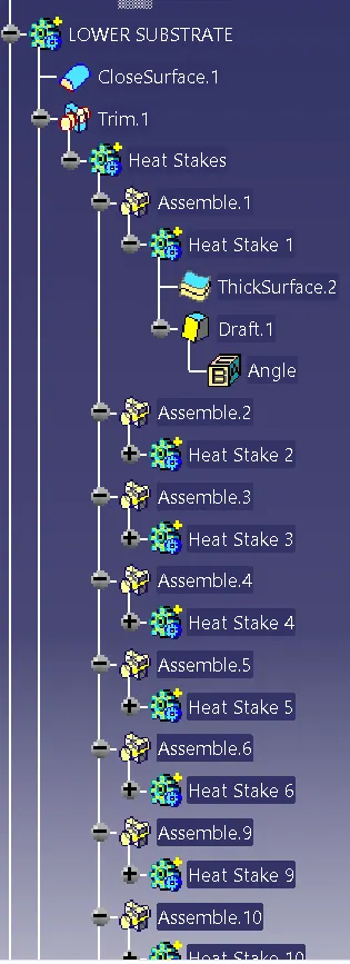
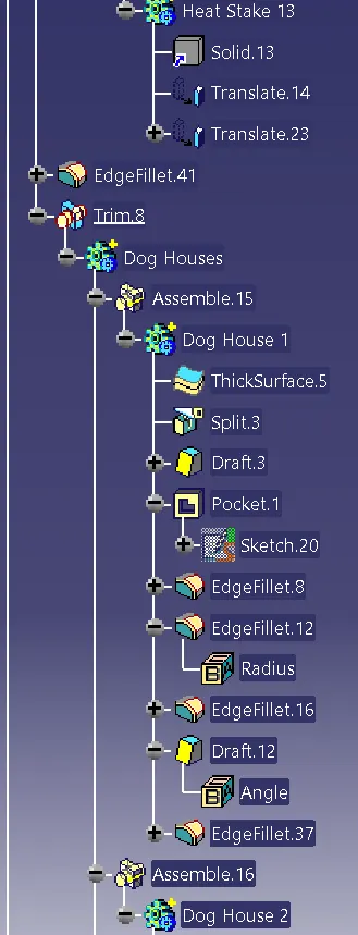
MODEL TREE -
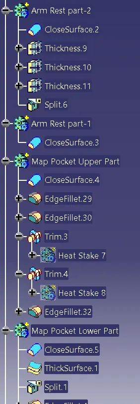
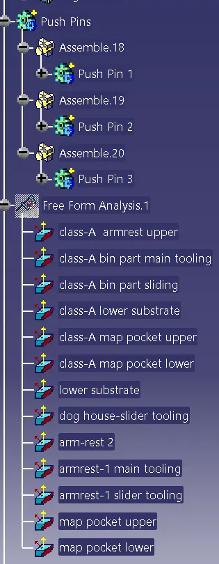
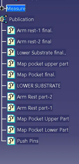
Result :-
isometric view-
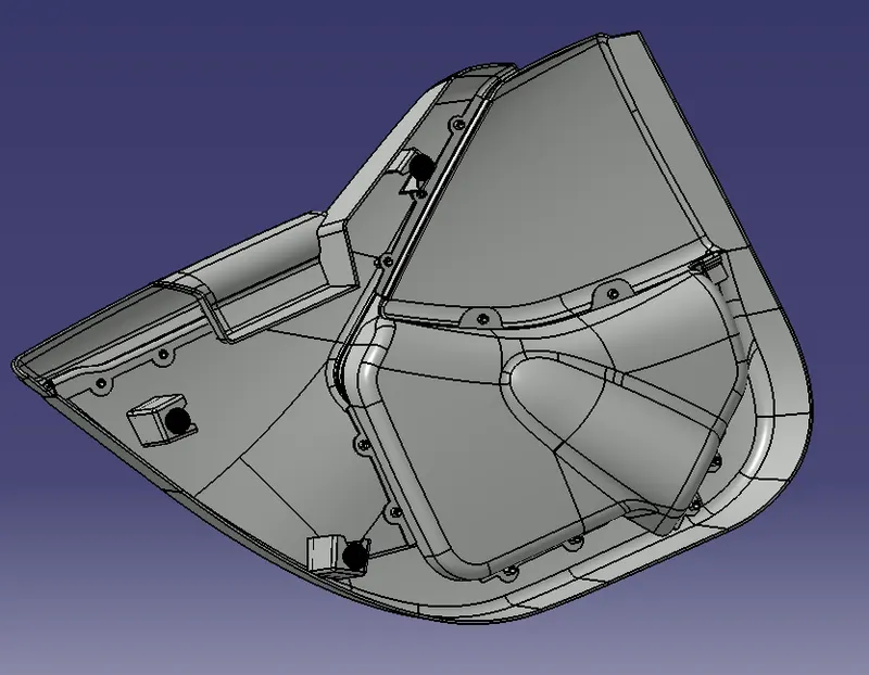
Front view-
Top view-