Week 11 - Final project
Week 11 - Final project
AIM
Development of a Door Trim panel. Creation of CAD model considering following inputs as like in OEM and tier1 companies.
Output Required
- Create thickened part using master section for reference
- Create the mounting features as per design guidelines in the industry and with master sections
- Apply material details :
- Draft analysis & Tooling analysis
REPORT
Class A Surface
Class A surface is a outer styling surface on which design engineer starts designing components.
Class B Surface
This surface is created by offsetting the Class A surface. The offset value is equal to the thickness of the component. On this surafce all the engineering features are provided.
Class C Surafce
The surface joining Class A and Class B in the tooling direction is known as Class C surface.
Heat Stakes
Heat staking is the process of joining two dissimilar materials together. In heat staking we use local heating and cooling to raise the temperature of plastic components and allow plastic reforming to be carried out. This reforming is converted into a shape that will hold the secondary component.
Ribs
Ribs are a feature in plastic injection molded parts. They are thin extensions that run perpendicular from a wall or plane. They are commonly used to provide additional support and strength to a part.
Dog House
Main use of Dog House is to avoid sink marks and install engineering features snaps, locators etc. on it. It also used to give support to long screw boss to reduce their height. And to fit screw bosses in the direction other than tooling axis.
Tooling axis is a direction in which core and cavity opens and closes. Draft angle is provided with respect to the tooling axis. While creating mold component from Class-A surface, we need to decide the tooling direction. It can be decided by visual inspection, deciding complex surfaces and bisecting method.
Tooling Axis Creation- Bisecting Method
- First check for the discontinuity of the surface received by join or boundary command. Then visual observation is done to decide which direction will be more feasible to create component.
- Few surfaces are identified which can create concern over draft angle
- A reference point is created in center of the bottom surface. And Axis system is created at that point.
- Two different cross section profiles are formed using intersection with plane.
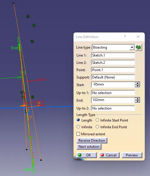
- For first profile in xy plane, Lines are drawn on the concerned boundary intersection profile. Then line is drawn bisectiong these two lines.
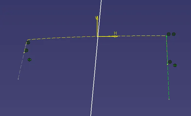
- For the second intersection profile in xy plane same procedure is followed.
- A bisecting line is created from the two lines created earlier with intersection profile. This bisecting line refered as Tooling axis line and this method is known as Bisecting method to create tooling axis.
Draft Analysis
To reduce the risk of damage to parts and tool while ejecting from mold a draft angle is provided to walls which are parallel to the tooling direction. It assists with releasing the part from mold.
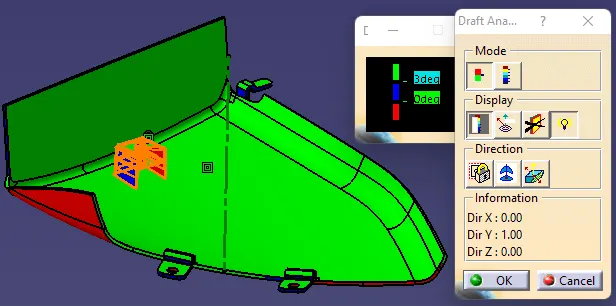
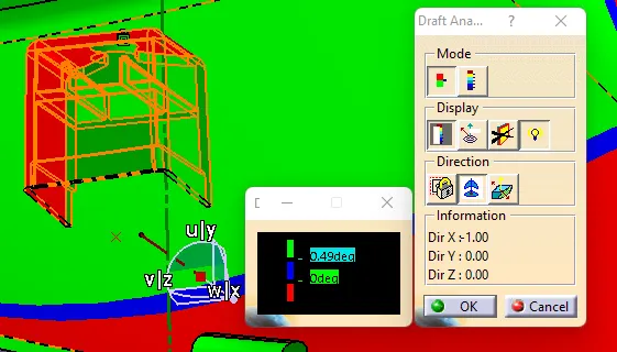
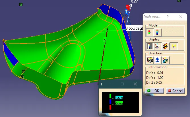
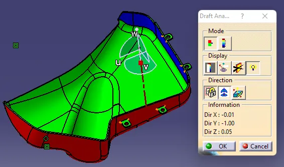
To perform Draft analysis in Catia, Draft analysis feature is used. For that First tooling Direction decided. Then make sure material view mode is used. After opening the window, align the compass with the tooling axis by dragging it on the axis. Then click on the surface or the body on which draft analysis is need to perform. In the bottom black colour window provide the minimum draft angle and then match the body color with this color scale. Green indicated draft angle is more than minimum draft angle. If it is blue then it is between 0 to minimum draft angle. And red denotes it is less than zero. By this way we can identify the areas with draft angle less than minimum draft angle and work on that area by changing tooling axis angle.
PROCEDURE
- First create a seperate files for every Class A surafce. And assemble them in CATProduct file and work on them seperately to create solid model as per master section design as per below steps.
- Check for Discontinuity. If any, join the surface. And Publish it as CLASS A surface
- Identify concern planes. Create line in every concern planes. From the these line create bisecting line ie. final Tooling axis.
- Perform Draft analysis on Class A surface in the Tooling Direction
- Create Class B surface by offseting Class A surface and join them by trimming. Fillet Edges. Or use fill by creating close profile.
- Create Class C surface by extracting boundary of class A surface and sweep it by minimum draft angle along the tooling direction.
- To create final closed surface body, join and trim all three surface together.
Lower Substrate 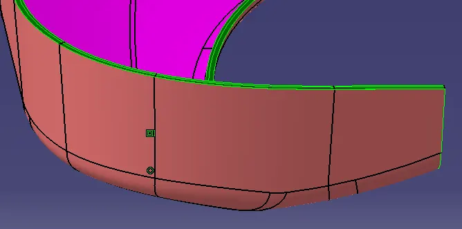
Armrest 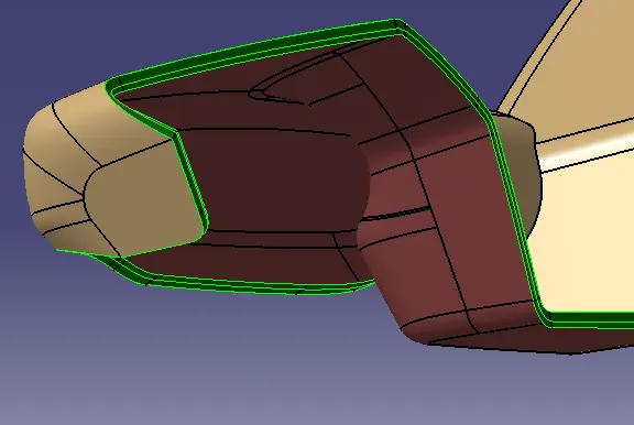
Map Pocket 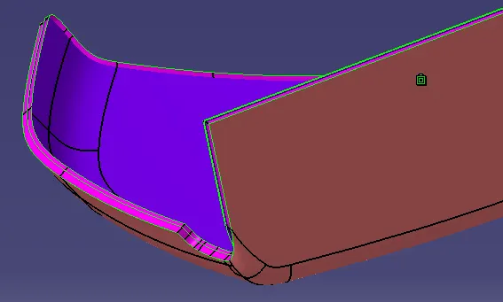
Bottle Holder 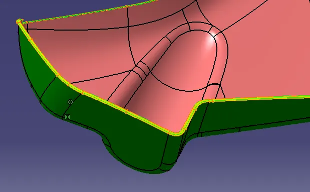
- Convert this surface body into Solid body by Close Surface Tool and give all the fillets and chamfer.
- Next step is to create Doghouse for Lower substrate and Map Pocket for push pins to fit sheet metal door part. Create a iso-constraint sketch, use pad, draft, and fillet features and add to the main body.
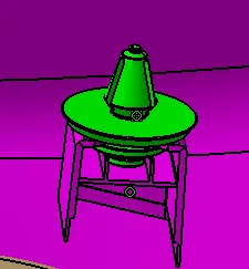
- In similar manner create heat stake on Lower substrate to join armrest, map pocket and bottle holder and translate it to the given points.
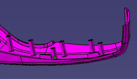
- Create Flanges to parts to join with heat stakes and at required positions as per master sections.
- Give fillets to all the attachments and finish the products.
Lower Substrate 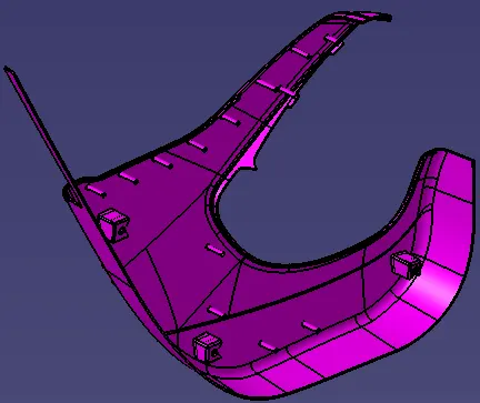
Armrest 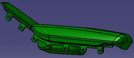
Map Pocket 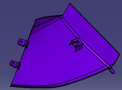
Bottle Holder 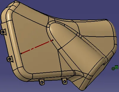
- Finally add the push pins to the assembly.
- Perform Draft analysis seperately on the Solid body, dog house and heat stakes with respect to their tooling axis.
RESULTS
Draft Analysis
1. Lower Substrate
Class A Surface- Minimum Draft angle 3 degrees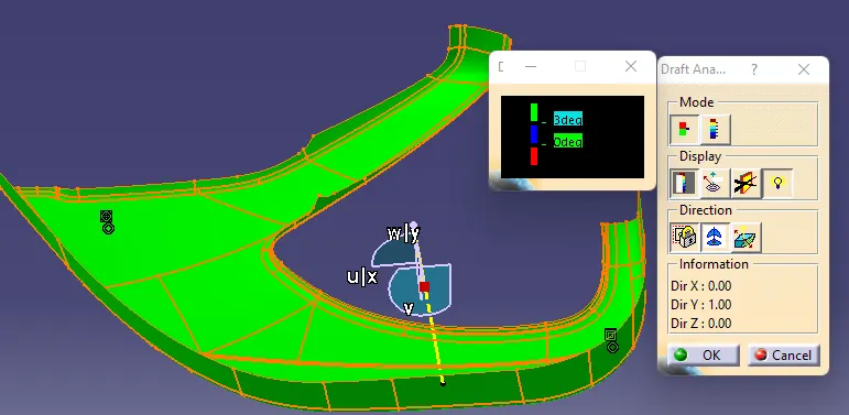
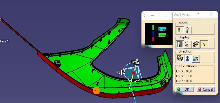
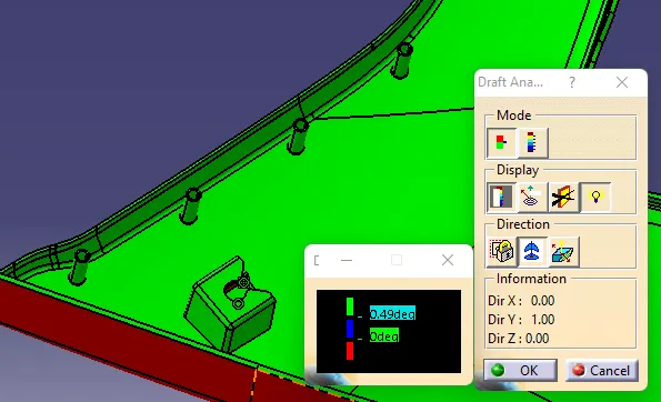
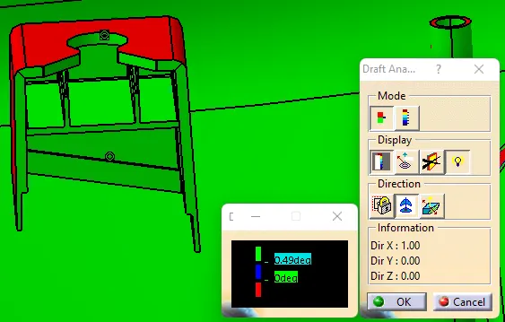
2. ARMREST
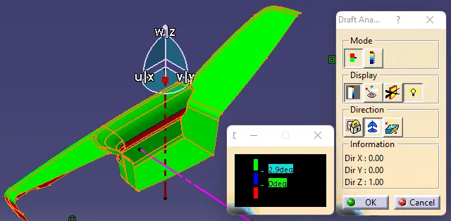
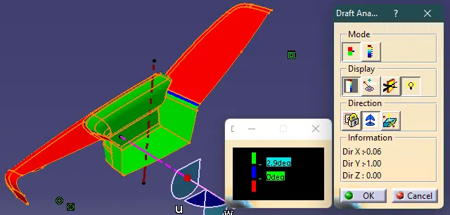
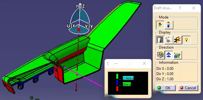
3. Map Pocket
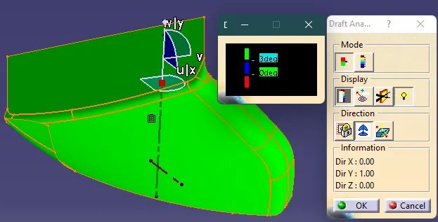
4. Bottle Holder
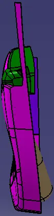
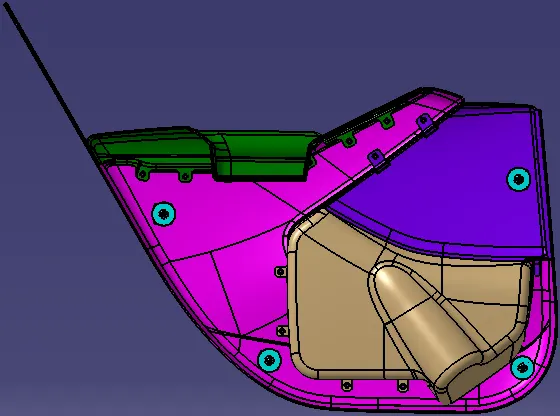
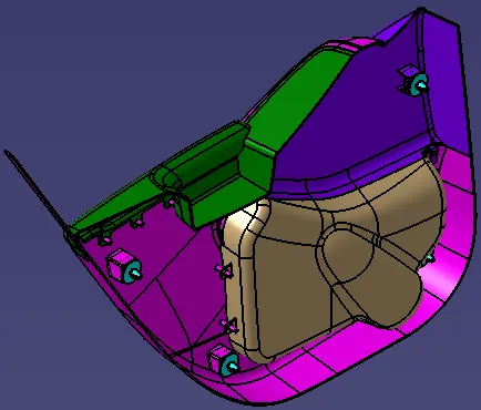
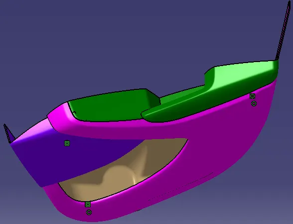
3D Model views
|
FRONT
|
SIDE
|
|
TOP
|
ISOMETRIC
|

Conclusion
Door trim panel is created from given class A surface as per given master given master section and joined together by creating attachments as per tier 1 and OEM industries rules in CATIA V5. And Draft analysis performed individually on each parts. At few portions, Class C has negative draft angle and also bottle holder which has draft angle positive but close to zero degree draft are need to be change. So, these parts are need to send back to styling team for modification.