Week 11 - Final project
AIM :
ABSTRACT :
The project report deals with the explanation of steps and procedure followed while developing the Door Trim Panel of a car using CATIA V5. Using the CLASS-A surface and master sections as input, we were able to create a Tooling axis, CLASS-B surface, CLASS-C surface, Flanges and form a solid body after which the attachment features such as Dog House, Push Pins, Heat stakes, etc are created. To check the manufacturability of the parts, a Draft Analysis has also been performed using the main/side tooling axis on various components such as
- Arm Rest
- Lower Substrate
- Map Pocket
- Bottle Holder
OUTPUT REQUIREDS :
- CLASS-A surface extraction
- Creation of different Geometrical sets for each component such as lower substrate, map pocket (upper & lower part), armrest (upper & lower part), etc.
- Tooling Axis / Side Core Axis Creation
- Creation of Flanges
- Creation of CLASS-B Surface
- Creation of CLASS-C Surface
- Joining of CLASS-A, B & C Surface
- Performing a check for boundaries
- Forming a Solid Body from closed surface
- Attachment features creation
- Performing Draft Analysis
THEORY :
CAR DOOR PANEL :
Door panels serve as an interface between the interior of the car and the inner workings of the door, and between vehicle occupants and the door. They are expected to meet a variety of design specifications regarding safety, aesthetics, and functionality. In addition, they are expected to continue the material theme of the dashboard and pillars while concealing intricate electrical and mechanical components for operating locks, windows, and other features. The door panel has evolved from a simple two-part system of latch and simple winding mechanism to a more sophisticated enclosure. Doors currently have an inner full-width panel consisting of electronic windows, central locking system, and speakers. These panels typically consist of a foamed core covered with either textiles or plastics.
Door panels are expected to meet one of the toughest sets of requirements among interior car components. These panels should be designed to withstand and channel loads into the body of the car while being thin (<2 mm). These loads could be horizontal and vertical in nature, like the force applied on opening or closing doors while leaning/resting on them or when stepping on the armrest to access the roof . An additional consideration is their ability to protect occupants from injury during a side collision, where most injuries are inflicted on the chest and pelvis as a result of crushing force of the door .
Federal Motor Vehicle Safety Standard No.214 therefore sets forth directives to manufacturers in order to limit this injury. It states that the Thoracic Trauma Index (TTI) should not exceed 85 g for a four-door or 90 g for a two-door passenger car. This test is performed at impact velocity of 53 km/h, which accounts for 90% of side impacts in North America.
Conventionally, door panels consisted of polyvinyl chloride (PVC) or polyurethane foamed core with appropriate textile fabric coverings. Subsequently, there was a shift toward thin-wall moldings of ABS or PP backed by textiles in order to manufacture a contour-backed panel with recesses. This is primarily because integrated injection-molded door panel assemblies reduce the need for other energy-absorbing materials, resulting in cost reduction for manufacturers due to simplification of door construction.
Door currently have an inner full width panel consisting of electronic windows, central locking system and speakers.These panels typically consists of a foamed core covered with either textiles or plastics.
Automotive Plastic Trim :
The design of Automotive Interior and Exterior plastic components is called Trims. The plastic components that you see inside the car are Interior. Ex: Dashboard, Instrument Panel, Doors, seating, and pillars. Plastic components that you see outside of a car are Exterior. ex: bumper, light assembly, hoods.
Plastic Part :
When designing parts for injection molding,the manufacturing process is an important consideration. Injection molding is a process in which solid thermoplastic resin pellets are melted, injected into a mold, and then cooled back to a solid state in a new form. During both the injection and cooling stages of the manufacturing process, there are several factors that may affect the quality of the final product and the repeatability of the manufacturing process.
PROCEDURE :
CLASS A & MASTER SECTION EXTRACTION :
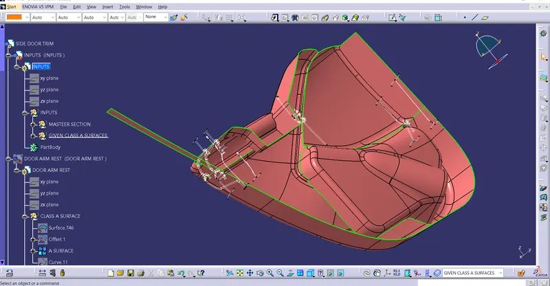
The first step to follow in this project is to extract the CLASS-A surface (individually for each component) of the Door Trim Panel and divide these surfaces into different Geometrical sets as follows.
- Lower Substrate
- Map Pocket Upper Part
- Map Pocket Lower Part
- Straight Arm Rest
- Inclined Arm Rest
We first check the given styling surface for any error in the surface elements. To do this we have to first extract the styling surface and then join it with the merging distance of 0.001 mm. This will show where the surface elements are weak. These weak sections have to be improved. The joined surface is then given as an input to the A-surface geometrical set.
We have to ensure that the Class A Surface for each part is connected as one single profile,to do that take Input file which has a single Geometric set with all the surfaces of the Class A Door trim then We have to extract and assign the respective surfaces to each component.
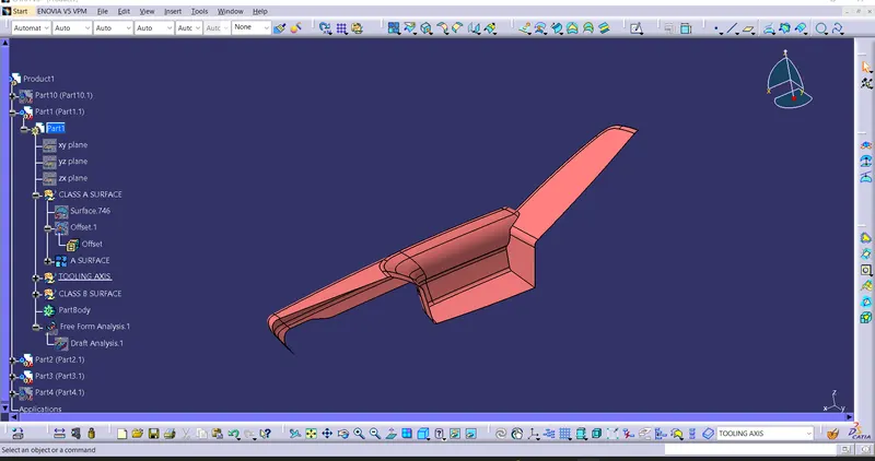
CLASS A OF ARM REST CONSOLE -
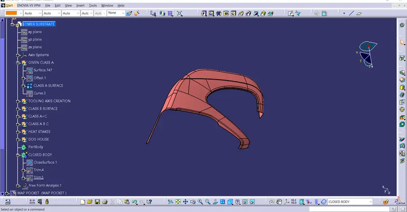
CLASS A OF LOWER SUBSTRATE -
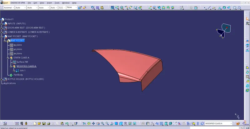
CLASS A OF MAP POCKET -
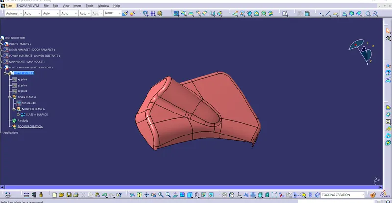
CLASS A OF BOTTLE HOLDER -
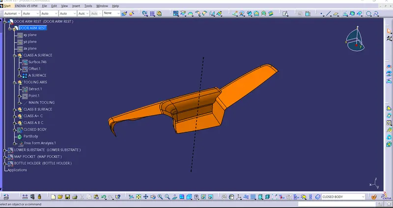
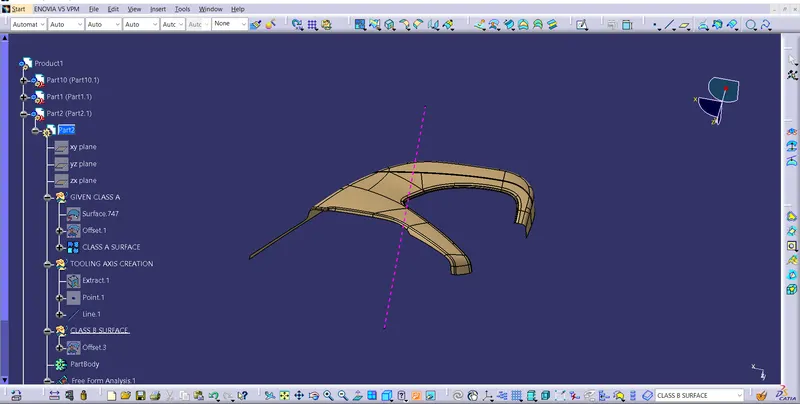
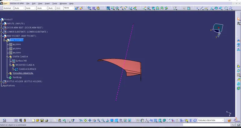
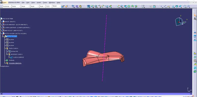
The next process or step is to create the tooling axis for the part which can be either made using the Biscecting method or using the Draft analysis approximation method. When checking the draft analysis all top surface has to turned green.
CONSTRUCTION OF TOOLING AXIS :
TOOLING CREATION :
Tooling direction is basically the direction that mold pulls apart. The mold is built in two seperate pieces, basically you have a cavity side and you have core side, The core pulls apart from the cavity and that's the Tooling direction. While creating a Tooling direction make sure that waterver that is created that is going to be used as a reference to design it may also include Ribs, Pockets, Walls Bosses etc. All are going to be drafted with respect to Tooling axis to make sure that the core can pull apart from the cavity nice and clean.
PROCESS :
since the extracted class A are of complex geometry for Bisection method to get the tooling axis ,even though we create it,it won't be accurate when we apply draft analysis on that tooling direction and also takes too much time and effort.so it is better if go with the trial method of moving compass until we get the satisfied analysis result to do that go to Insert > Analysis > Feature Draft Analysis and Simply place the compass on the largest flat surface then Check the Analysis by Tilting the Compass by Orientation or Rotation about an axis to get the desired result. After choosing the particular orientation,lock the compass direction.
now we have locked the definite direction of tooling axis now we will create a straight line which itself will be tooling axis.first we create a point on the surface before creating tooling axis.
TOOLING CREATION FOR ARM REST :
TOOLING CREATION FOR LOWER SUBSTRATE :
TOOLING CREATION FOR MAP POCKET :
TOOLING CREATION FOR BOTTLE HOLDER :
DRAFT ANALYSIS FOR GIVEN CLASS A :
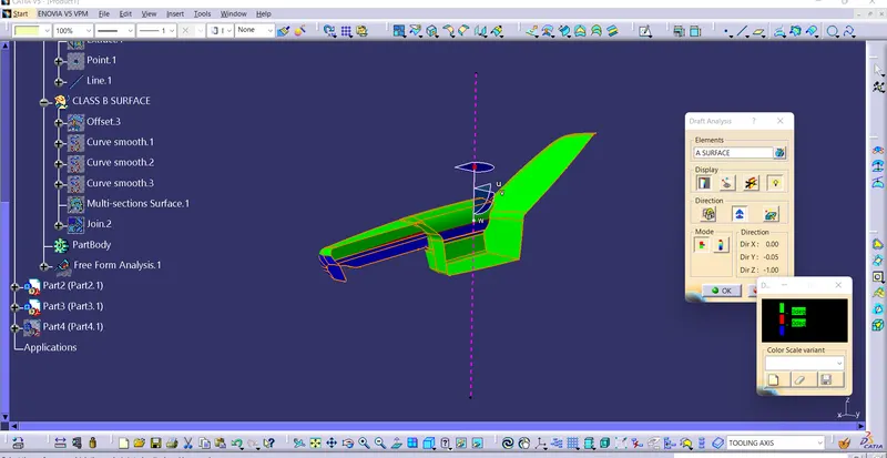
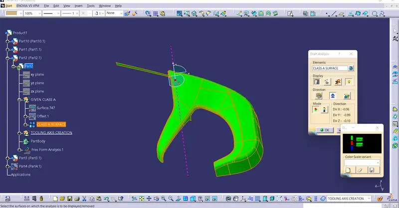
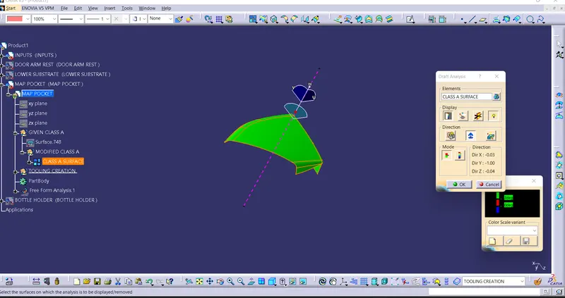
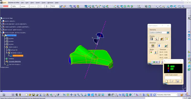
No parts can be ejected from the tool if it is having a straight 90 degree profile from its base surface. A small draft angle is provided to each and every area of the component in order to get an easy removal of the component from the tool.
Draft analysis technique is used to analyze whether our part model created in cad is manufacturable based on the draft condition applied. Here the part should get easily removed from the panel dies (in case of Sheet metal part) or Mold (in case of plastic).
Here we are providing a direction in which components should eject inorder to get an easy removal of components from the tool. In other words it also lets us know whether the model is having a draft angle and how much is the draft angle from the tool direction.
DRAFT ANALYSIS FOR ARM REST :
DRAFT ANALYSIS FOR LOWER SUBSTRATE :
DRAFT ANALYSIS FOR MAP POCKET :
DRAFT ANALYSIS FOR BOTTLE HOLDER :
CREATING B SURFACE :
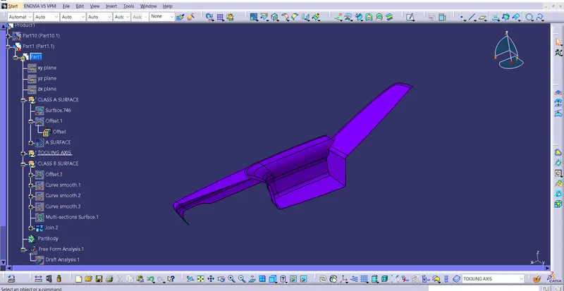
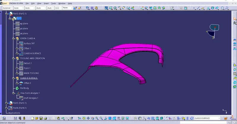
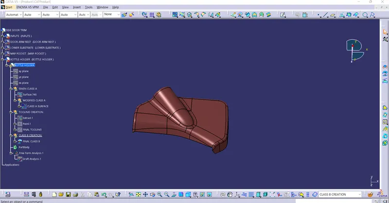
Class B surfaces are the secondary surfaces that you may see sometimes or may not, but are less important. These must be smooth and "error-free" as well, but are not held to the standards that class A surfaces are. After creating the Tooling axis, B surface is to be created which is nothing but the surface parellel to the A surface. B surface contain all the fillets and the edges which the A surface containsDepending on the geometry, the extraction and offset of the fillets might generate non-uniform thickness. So it is advisable to extract only the flat surfaces and then apply fillets at the end of Class B formation.
lets start the process of creating class B by choosing the respective A surface and extract with no propagation option then untrim the extracted surface to get the basic geometry.after getting the original/basic surface the surfaces have to overlap each other in order to facilitate trimming therefore extrapolate it up to the required dimension.then we finally trim them.
now after trim operation is done offset the Trimmed geometry by the value of the thickness of the component,this Offset is our B Surface.at last We will measure the filler radius values to create fillets on the class B
ARM REST :
LOWER SUBSTRATE :
MAP POCKET :
BOTTLE HOLDER :
CREATION OF C SURFACE :
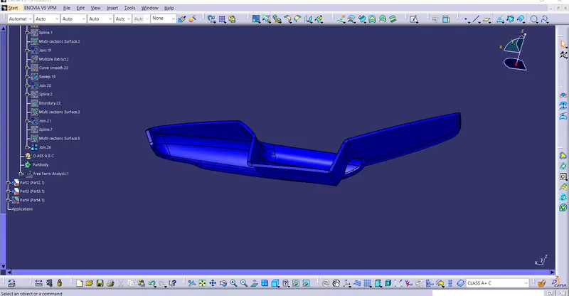
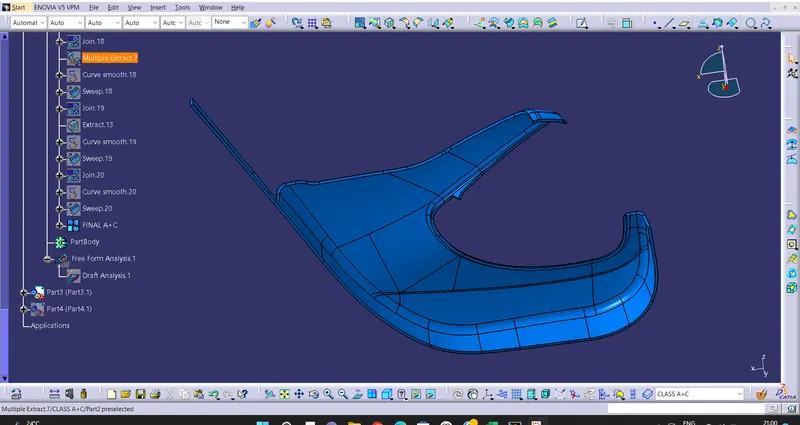
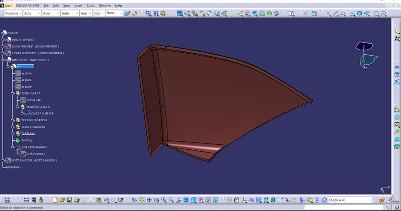
Class C surface for this component is created using sweep command. All the ends of component surface are facing downwards, so the C surface will be created perpendicular to B surface.
To create C surface, boundary of class A surface and surfaces adjacent to boundary are extracted. Then sweep with reference surface command is used and surface is created at 90 degree.
ARM REST :
LOWER SUBSTRATE :
MAP POCKET :
BOTTLE HOLDER :
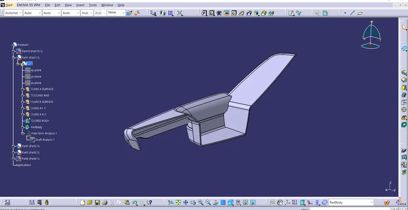
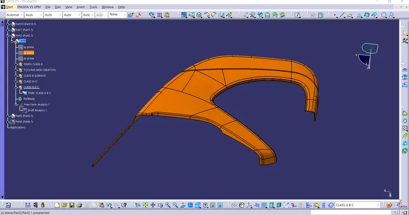
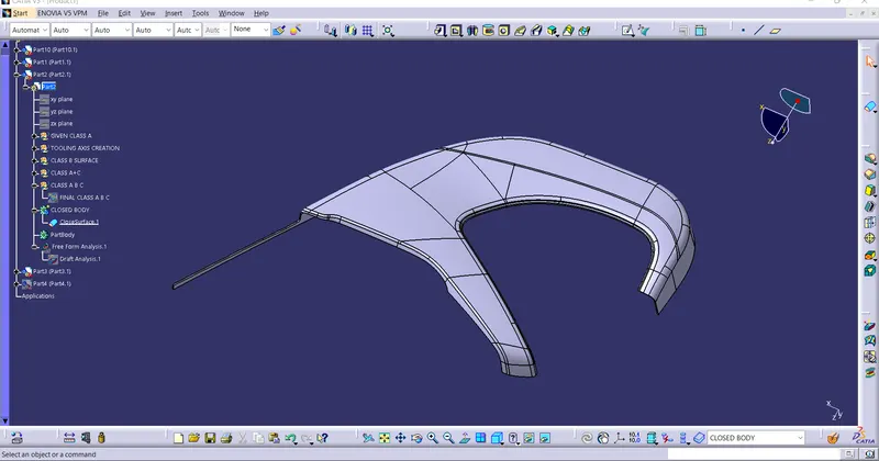
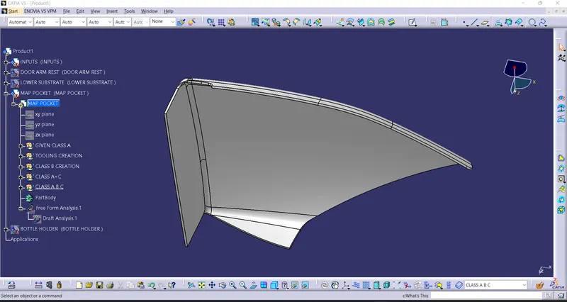
CREATION OF FINAL SOLID BODY :
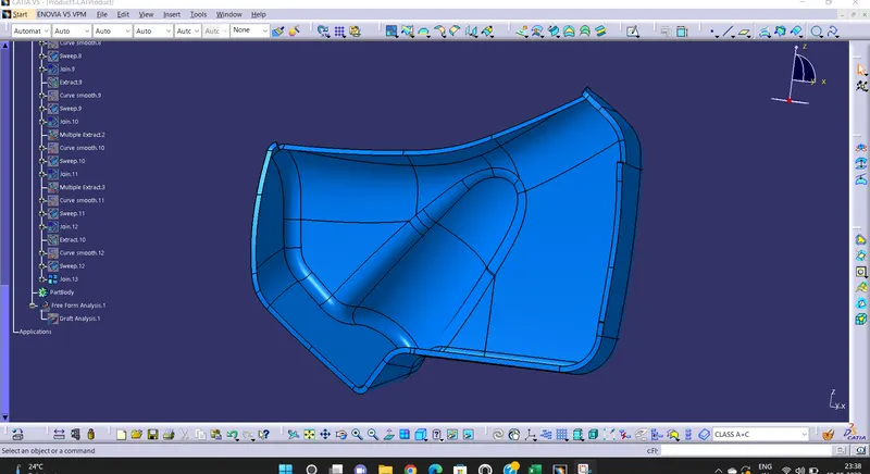
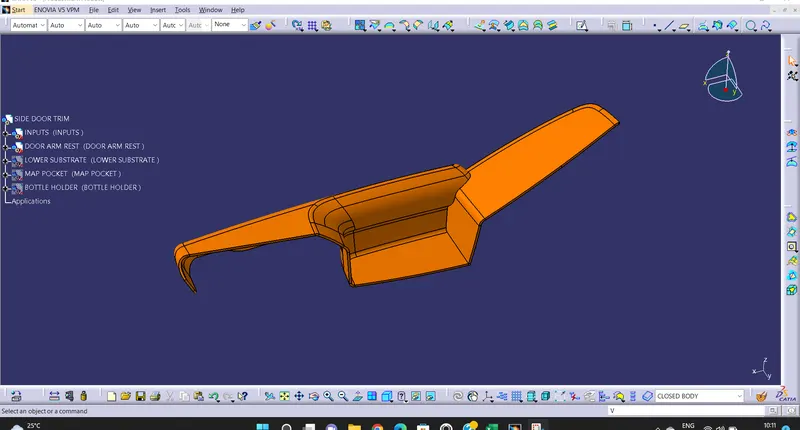
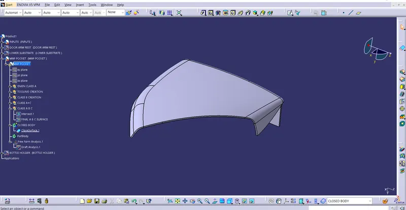
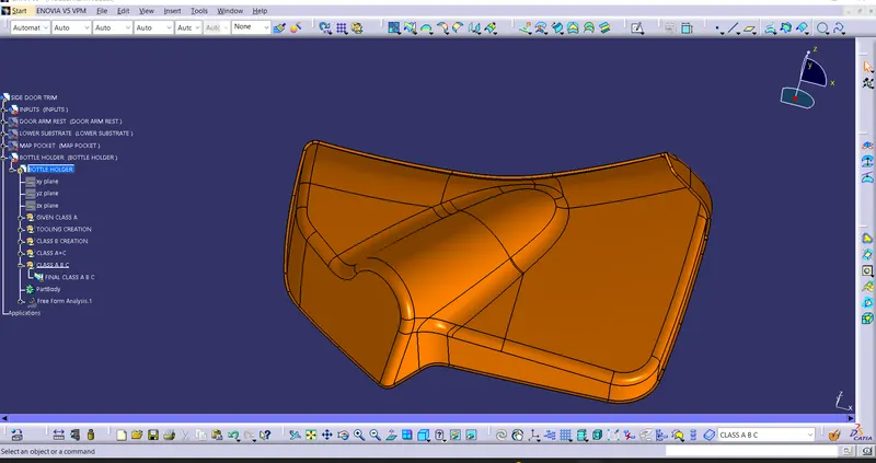
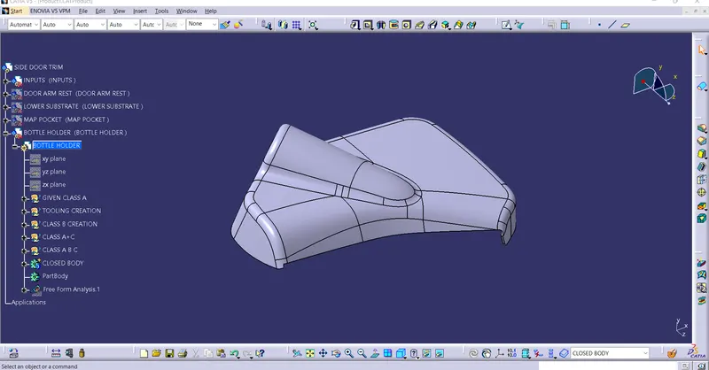
Once all surfaces are created, Class A, B and C surfaces are joined together to get the final closed volume. This closed volume is then converted into solid body using closed volume command in part design work bench.
ARM REST :
LOWER SUBSTRATE :
MAP POCKET :
BOTTLE HOLDER :
DRAFT ANALYSIS OF FINAL COMPONENTS :
Draft analysis is done on final component to check manufacturing ability. The walls of the bin are having zero draft angle with tooling axis. This will be ignored since it is given in class A surface.
ARM REST :
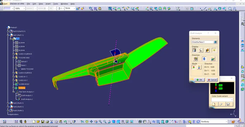
LOWER SUBSTRATE :
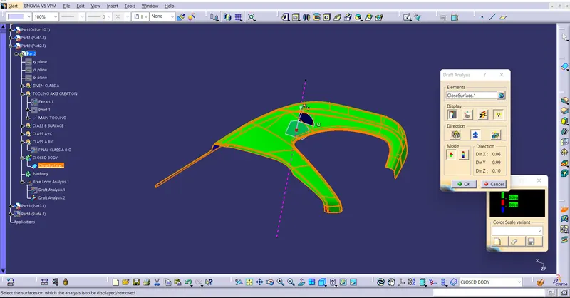
MAP POCKET :
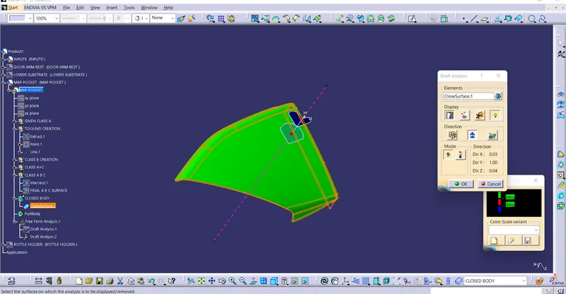
BOTTLE HOLDER :
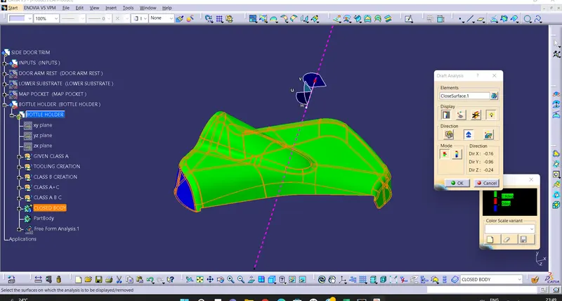
ADDITION OF FLANGES WITH RESPECT TO MASTER SECTION :
A flange is a protruded ridge, lip or rim, either external or internal, that serves to increase strength for easy attachment/transfer of contact force with another object or for stabilizing and guiding the movements of a machine or its parts. The term "flange" is also used for a kind of tool used to form flanges.
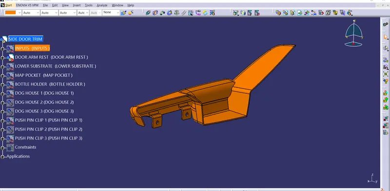
TRANSLATION AND OF PLASTIC FEATURES
After creating a single feature, we can translate it multiple times to the desired location.First Copy the respective feature's part body into the main part file Copy > Paste Special > As specified in Part Document this removes the Parent-Children relationship and we can edit the translated part according to our needs.
Holes on flanges for fixation :
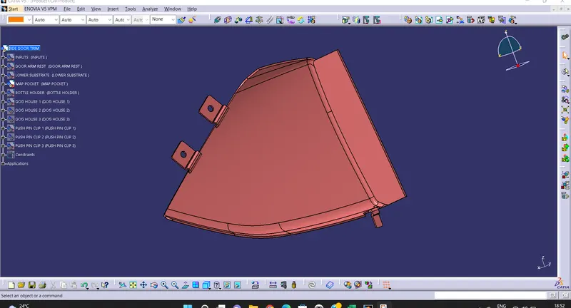
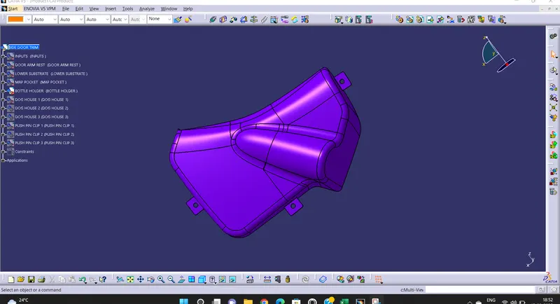
The door trim Assembly has to be rigidly fixed as one unit.The 4 components will be permanently arrested to the Lowered substrate by using the Heastakes.The Heatstakes will pass through the flanges of the components, therefore some clearance of 0.1mm has to be provided.
HEAT STAKING -
Heat Staking is a pulsed-heat process to join two or more parts out of which one at least is made of plastic. The process is to deform the plastic material using heat and force at a set process time. The bond is made by partially de-forming the plastic part in order to fix the other. Heat Staking makes it easy to bond metal to plastic and is commonly used in high volume/low cost applications such as automotive, IT and consumer appliances.
Shaping Plastic Using Heat and Pressure :
The plastic is deformed by heating it to a temperature above the glass transition temperature. Super-heated air or a thermode is used for this. Pressure is then applied to create the stake. After the stake has been formed, the plastic should be cooled down again below the glass transition temperature. Cooling is performed under constant pressure to ensure good fixation of the parts. Compressed air can be applied for cooling when a thermode is used. Heat is used to facilitate the creation of the stake. Heat control is critical, especially for glass-filled plastics which often have a process window of less than 10 degrees Celsius. When the temperature is too high, the glass fibres come out of the plastic which leads to a rough surface and adhesion to the thermode. If the temperature is too low, the plastic will crack due to cold deformation.
Heat staking Benefits :
- Similar and dissimilar materials may be joined: metal to metal, plastic to plastic, metal to plastic
- Accurate control operating within a small process window
- Local heating resulting in no damage to surrounding materials
- Processing of glass-filled materials
- No mechanical vibration
- Many heat-stake shapes possible through custom designed tools
Heat Stakes Design :
- First, extract the class 'A' boundary and use parallel curve commapnd to offset the extracted curves.
- Use point and plane repitation command for points on the curves.
- Create sketch by taking door attachment class 'A' surface as refrance.
- Pad the sketch upto certain limit and use design rules as per Screw boss design.
- Use 0.5 degree draft with pulling direction as tooling axis.
- Give Fillate
- Union Trim with Door Applique.
- Use Translet command for number of same locators.
DESIGN OF GUSSETS TO SUPPORT HEAT STAKES :
GUSSETS :
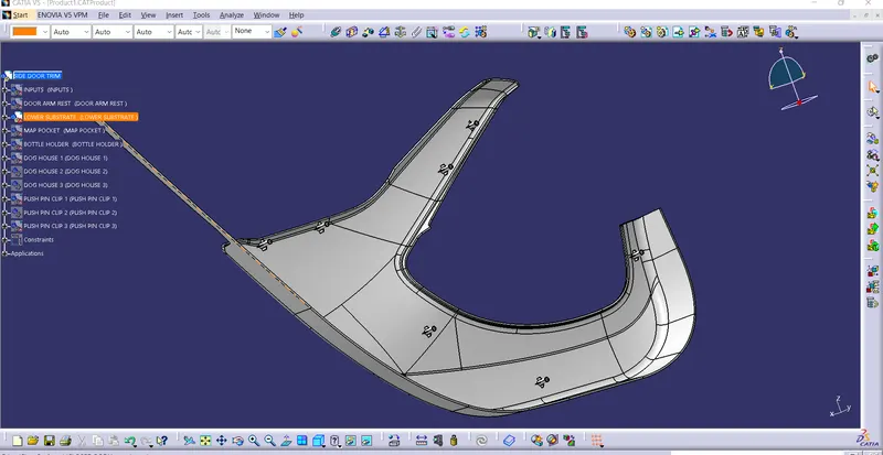
Gussets are rib-like features that add support to structures such as bosses,ribs,and walls. As with ribs, limit gusset thickness to one-half to two-thirds the thickness of the walls to which they are attached if sink is a concern. Because of their shape and the EDM process for burning gussets into the mold, gussets are prone to ejection problems. Specify proper draft and draw polishing to help with mold release.
Create a straight line sketch using the surface as support.In the Surface workbench, Extrude the line in the direction of the Tooling axis.Go to the Part workbench and add Thickness to the extruded surface.
DOG HOUSE -
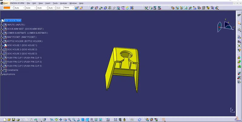
Dog house is an engineering feature used in plastic trim design. Dog houses are used as supporting feature. Sometimes other engineering features like snaps; locators etc. are mounded on them to increase their strength. Dog houses are subjected to draft analysis to prevent breakage of the component during ejection from mould cavity. Dog house and other engineering components are built on B-surface.
IMPORTANT FUNCTION OF DOG HOUSE -
- Helps to avoid sink marks.
- solves the length issues(ex: screw bosses can be formed at 100mm form B-surface).
- Always design houses perpendicular to the tooling axis.
PUSH-PIN CLIPS :
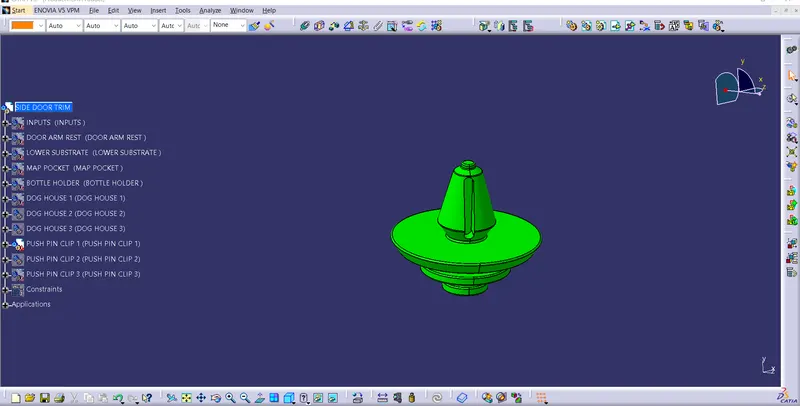
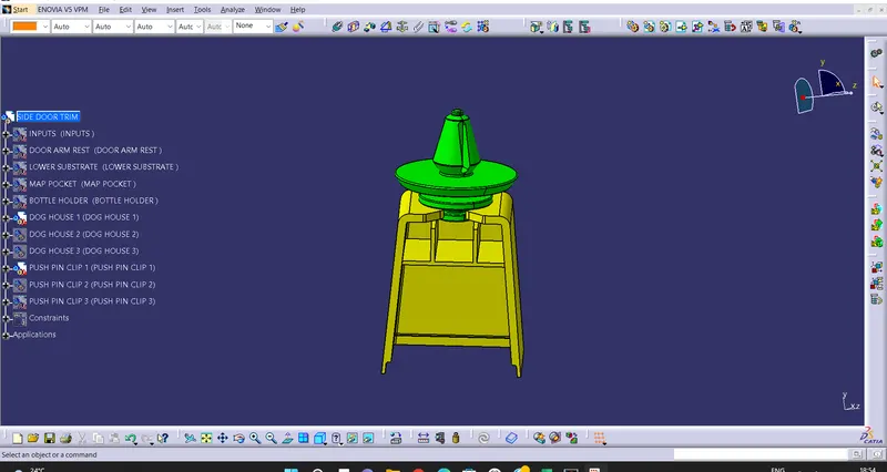
Pushpin which helps us in Locating and Arresting components of an Assembly and it provides Alignment in Mating Parts and it also acts as a stopper or guide for various mechanisms.
BOTTOM-UP ASSEMBLY :
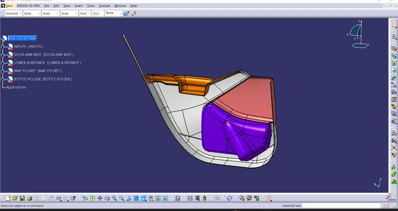
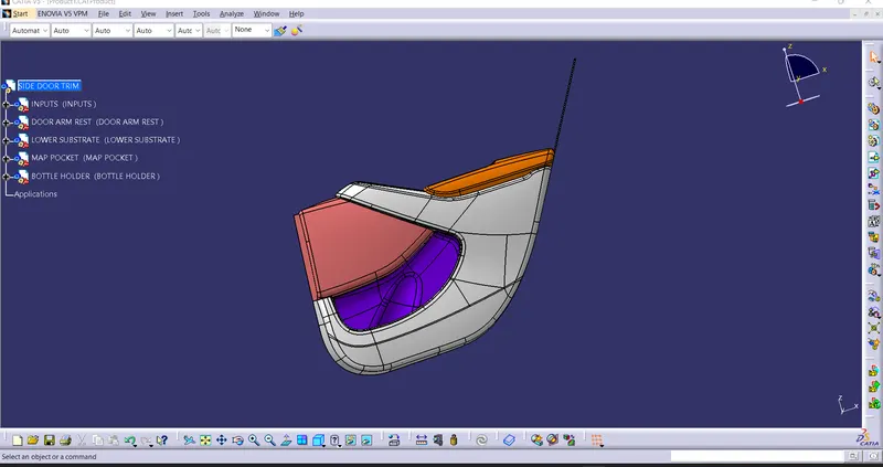
The components are created in separate part files and are then inserted into the assembly file. They are assembled at their working position by applying assembly constraints to them. To create an assembly using this approach, it is recommended to insert the first component and fix its position after properly orienting it in the 3D space. The other components can be inserted and positioned with reference to the first component.
RESULT :
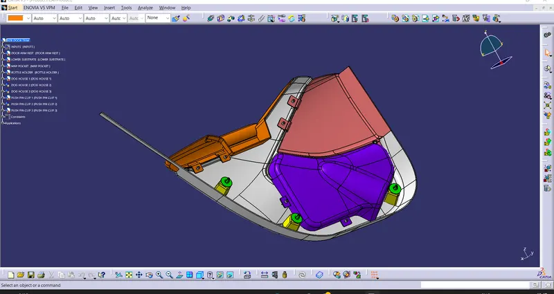
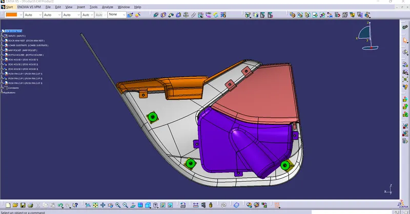
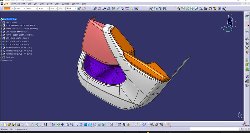
Finally,the Interior trim of the Car interior door trim is designed using the given A Class Surface as the Input and B and C Class Surfaces are created with respect to the A Class Surface for the components listed down below:
- Arm Rest
- Lower Substrate
- Map Pocket
- Bottle Holder