Week 11 - Final project
Development of Door trim panel
Aim : To Create the Door Trim panel through the given Class-A surfaces by creating a required tooling axis and various attachments.
In automotive design a Class A surface in any of a set of free form surfaces of high efficiency and quality. Although strictly its nothing more than saying the surfaces have curvature and tangency alignment to ideal aesthetical reflection quality, many people interpret class A surface to have G2 or even G3 curvature continuity to one another. Class A surfacing is done using computer aided digital applications. Class A surface modellers are also called digital sculptors in the industry.
Procedure for Designing Door Trim:
To start with is to download and open the below class A file of the door trim.
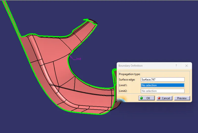
Now check the continuity of the surfaces using boundary option. There should not be not gap between the surfaces.
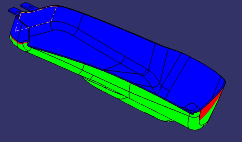
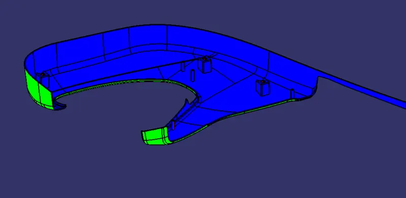
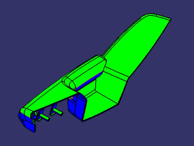
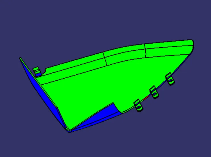
The panel is divided in manly four components,
- Lower substrate
- Upper substrate
- Map pocket
- Arm rest
The door panel is the interface between the interior of the car and inner working of the door. Generally, the door panel is divided in to parts for easy designing like arm rest, map pocket, lower substrate. These require one of the toughest requirements among the interior parts of the car. This should be designed to with stand the load while being less than 2mm in thickness and also to protect the occupants during collisions.
Each component has to be seperately created, all will have different tooling and side axis.
1. Lower Substrate
First we have to check the boundary continuity. If there is no gap create a tooling axis.
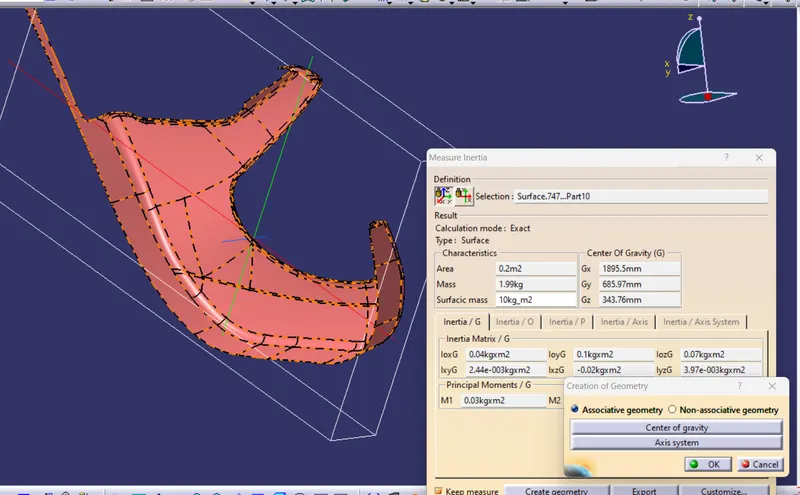
Now create a center point by moment of interia option  . Create an axis system along the point.
Create a line along the y axis and the point the created after examine the surface.
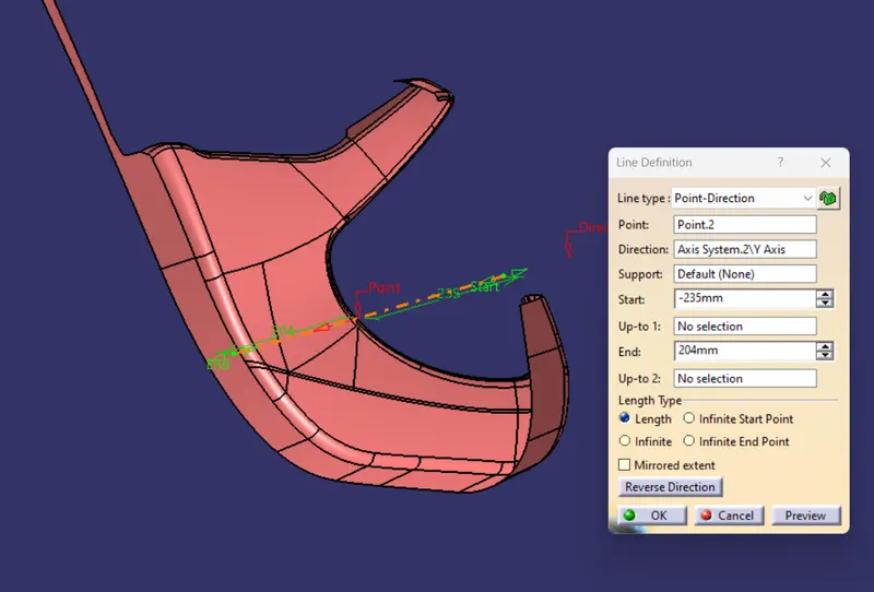
This line is named as tooling axis for lower substrate.
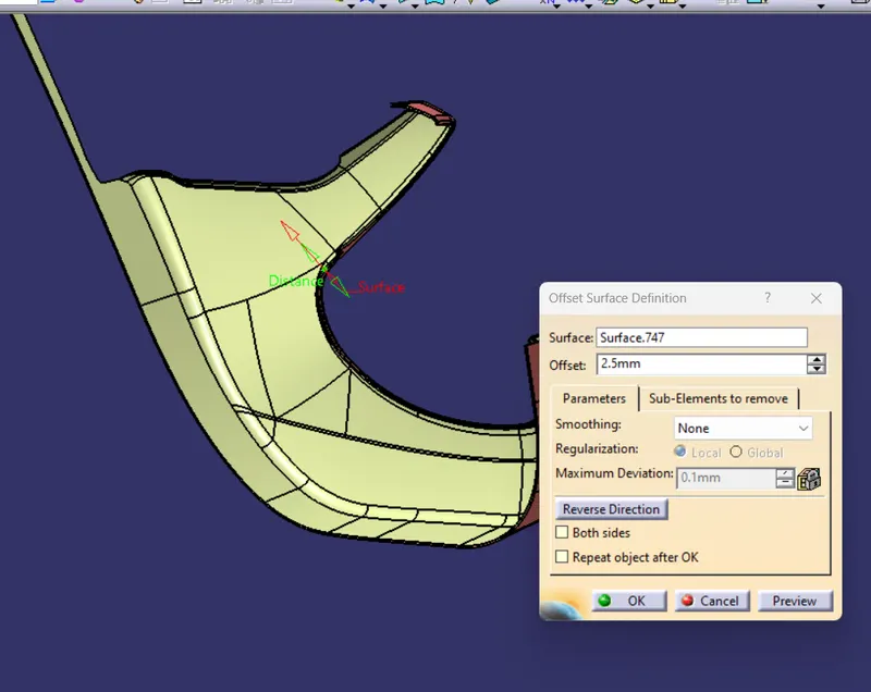
Next create a class B surface by offsetting the class A surface by 2.5mm in the direction referrring the given master section.
Next is to create the class C surface.
First the boundary of class A is extracted and using sweep option the the surface is created.
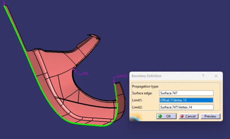
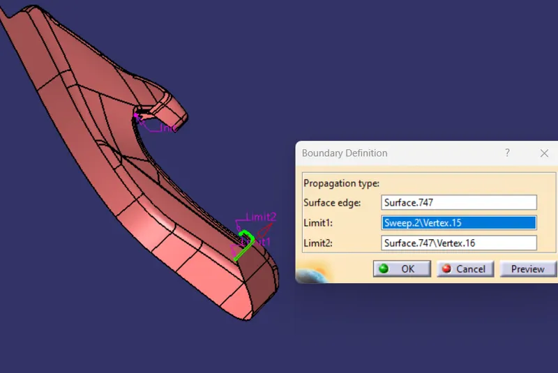
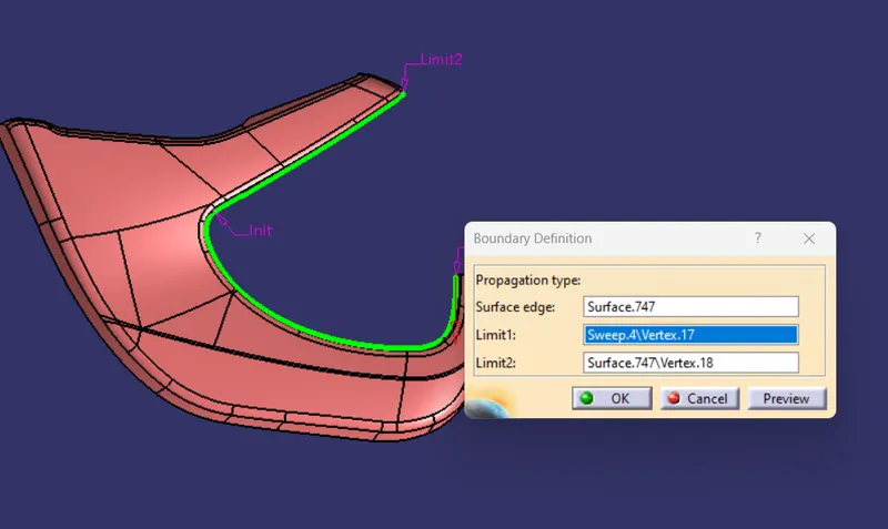
Here the boundary is extracted seperately for obtaning smooth sweep operation.
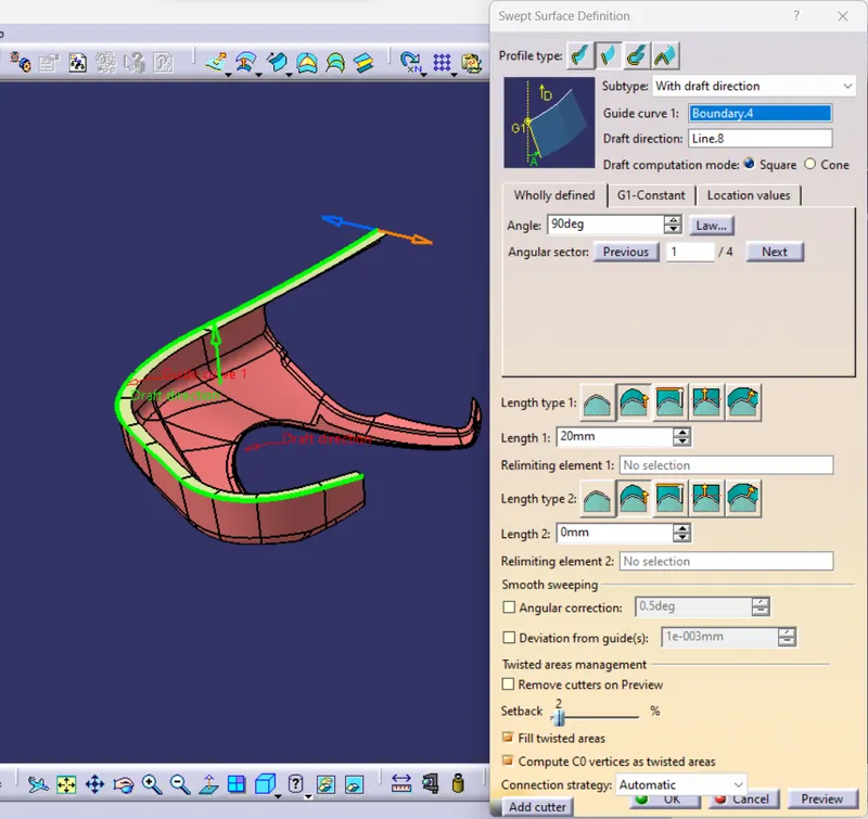
Once the sweep is done, the class B surface is further extended so that the intersection between the class C and class B surface.
Using split command the class C is created.
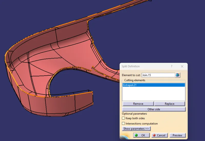
Now the class C and class A surface are first joined and then trimmed with the class B surface to obtain the final closed component.
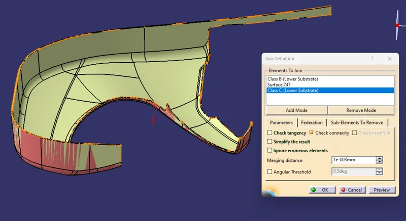
Since there is no open edges, we can proceed to creating solid.
Open part design workbench and click close surface , select the surface body and click ok
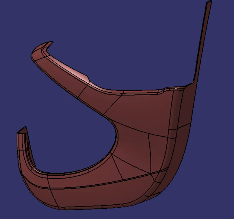
Similarly, the other components are created.
2. Arm rest:
First we have to check the boundary continuity. If there is no gap create a tooling axis.
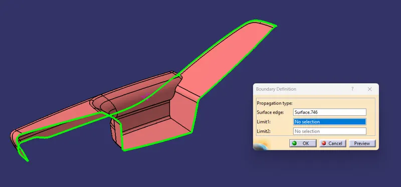
Now create a center point by moment of interia option . Create an axis system along the point.
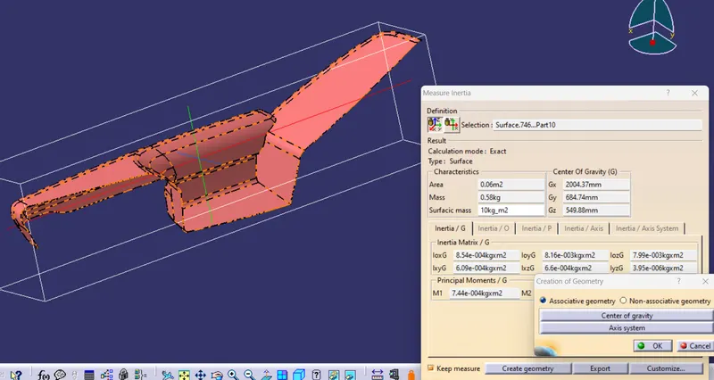
A temporary axis is created at the bottom flat surface of the arm rest.
A intersection is created along the xz plane.
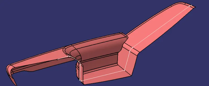
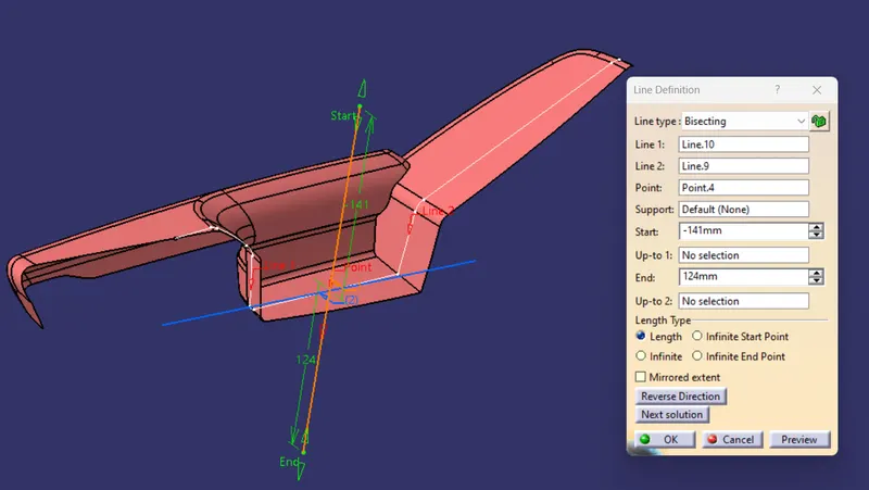
Draw two lines and create a bisecting line between the two lines
Similary create insection and obtain a bisecting line along the yz plane. Now create a bisecting line using 2 bisecting lines created.
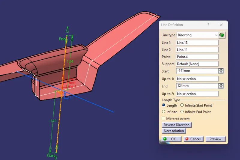
This line is named as tooling axis for arm rest.
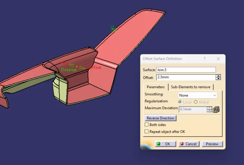
Next create a class B surface by offsetting the class A surface by 2.5mm in the direction referrring the given master section.
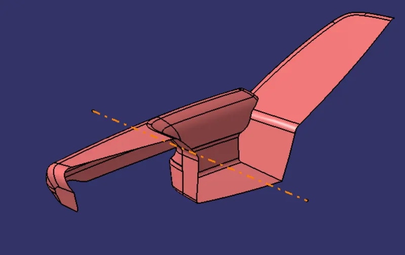
Create a slinging axis along a Y axis as shown below.
Next is to create the class C surface.
First the boundary of class A is extracted and using sweep option the the surface is created.
If there is any gap during the sweep, do it by part by part and join overall to obtain the final result.
Here the boundary is extracted seperately for obtaning smooth sweep operation.
Once the sweep is done, the class B surface is further extended so that the intersection between the class C and class B surface.
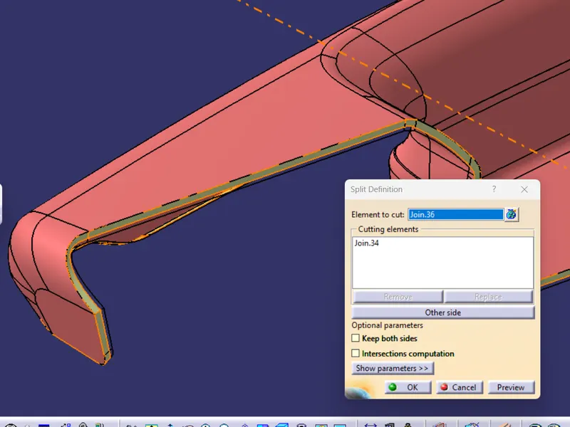
Using split command the class C is created.
Now the class C and class A surface are first joined and then trimmed with the class B surface to obtain the final closed component.
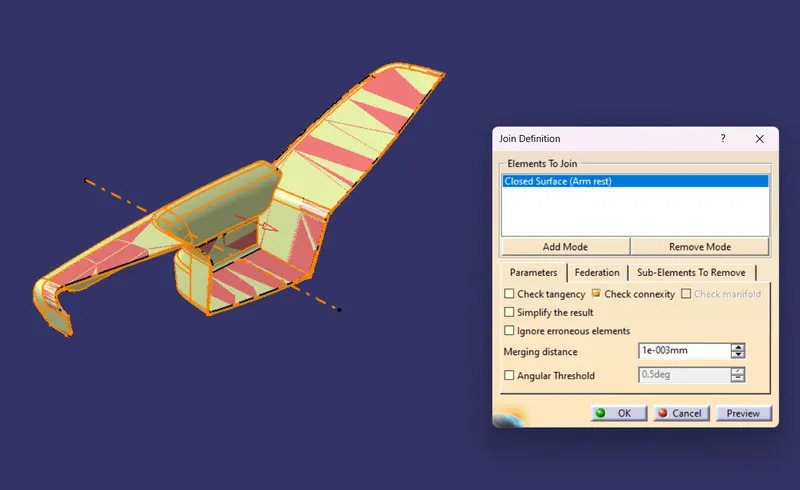
Since there is no open edges, we can proceed to creating solid.
Open part design workbench and click close surface , select the surface body and click ok
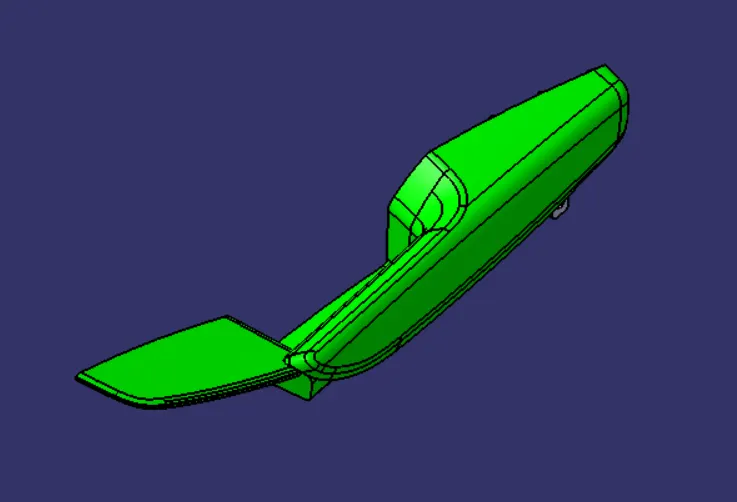
3. Map pocket:
First we have to check the boundary continuity. If there is no gap create a tooling axis.
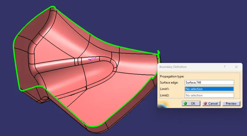
Now create a center point by moment of interia option . Create an axis system along the point.
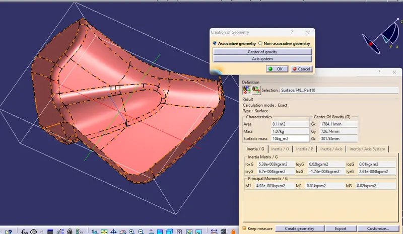
A intersection is created along the xz plane.
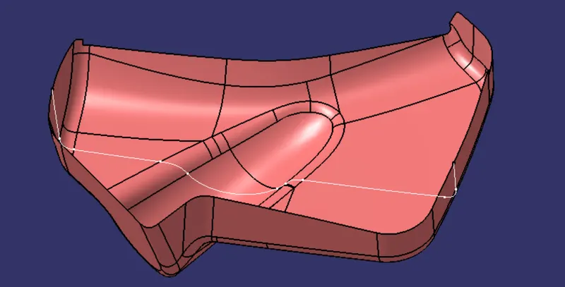
Draw two lines and create a bisecting line between the two lines.
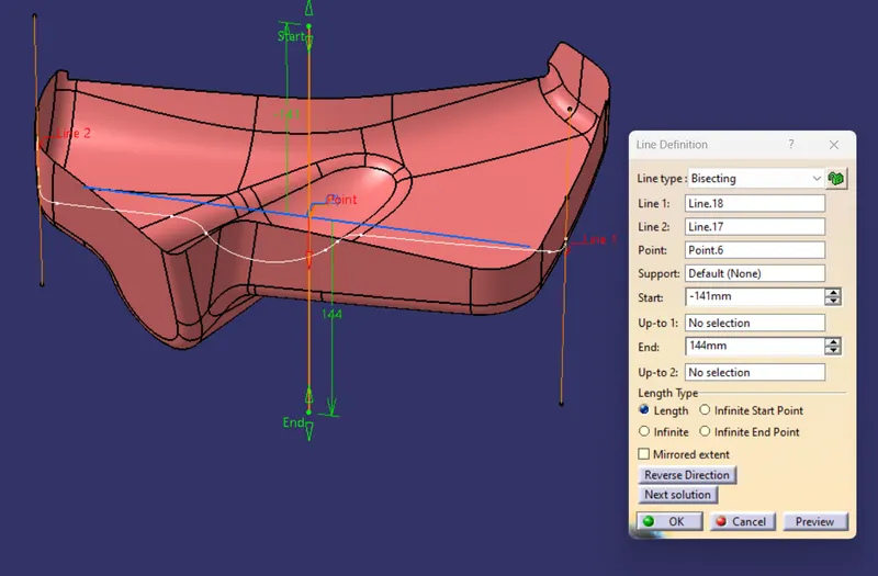
Similary create insection and obtain a bisecting line along the yz plane. Now create a bisecting line using 2 bisecting lines created.
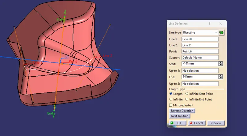
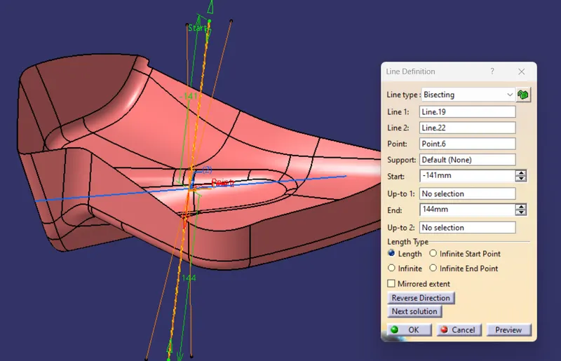
This line is named as tooling axis for map pocket.
Next create a class B surface by offsetting the class A surface by 2.5mm in the direction referrring the given master section.
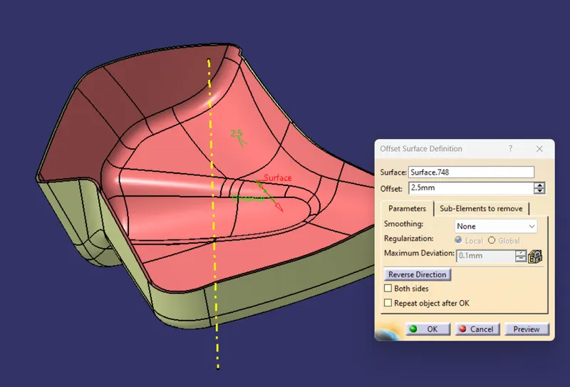
Next is to create the class C surface.
First the boundary of class A is extracted and using sweep option the the surface is created.
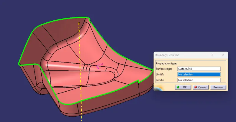
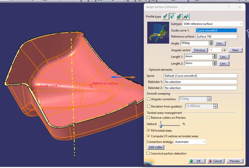
Here the boundary is extracted seperately for obtaning smooth sweep operation.
Once the sweep is done, the class B surface is further extended so that the intersection between the class C and class B surface is obtained.
Using split command the class C is created.
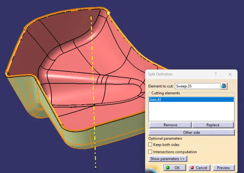
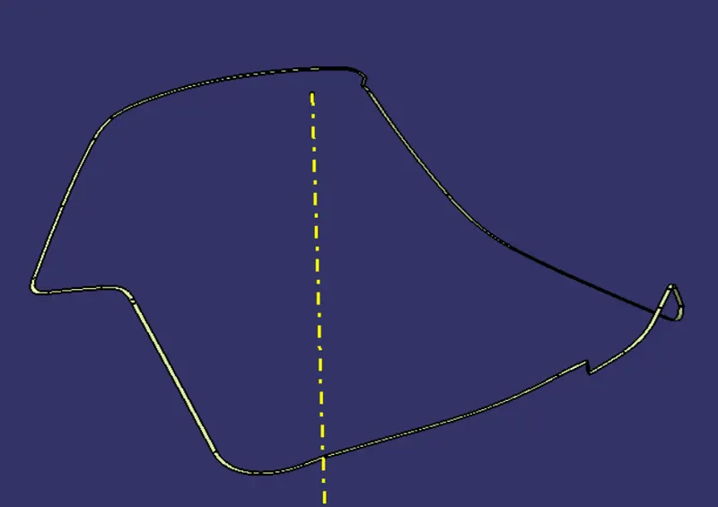
Now the class C and class A surface are first joined and then joinned with the class B surface to obtain the final closed component.
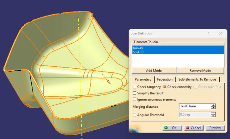
Since there is no open edges, we can proceed to creating solid.
Open part design workbench and click close surface , select the surface body and click ok
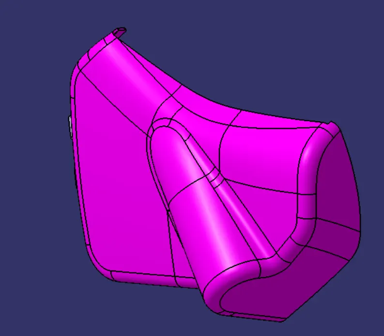
4. Upper Substrate:
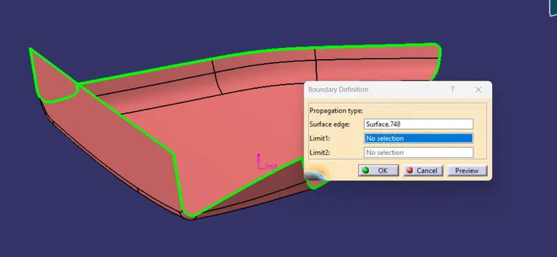
First we have to check the boundary continuity. If there is no gap create a tooling axis.
Now create a center point by moment of interia option . Create an axis system aolngthe point.
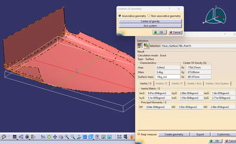
Create a line along the y axis and the point the created after examine the surface.
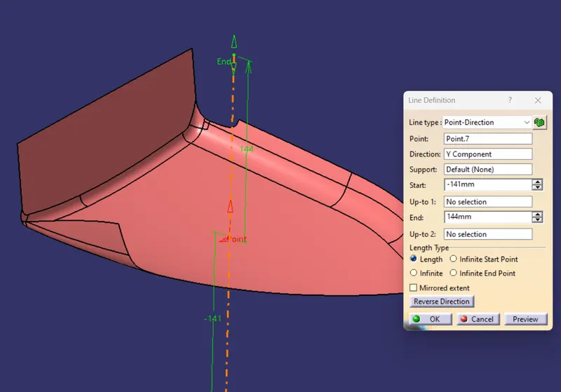
This line is named as tooling axis for upper substrate.
Next create a class B surface by offsetting the class A surface by 2.5mm in the direction referrring the given master section.
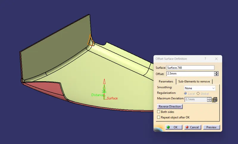
Next is to create the class C surface.
First the boundary of class A is extracted and using sweep option the the surface is created.
Here the boundary is extracted seperately for obtaning smooth sweep operation.
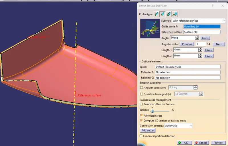
Once the sweep is done, the class B surface is further extended so that the intersection between the class C and class B surface.
Using split command the class C is created.
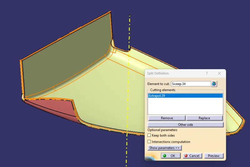
Now the class C and class A surface are first joined and then joinned with the class B surface to obtain the final closed component.
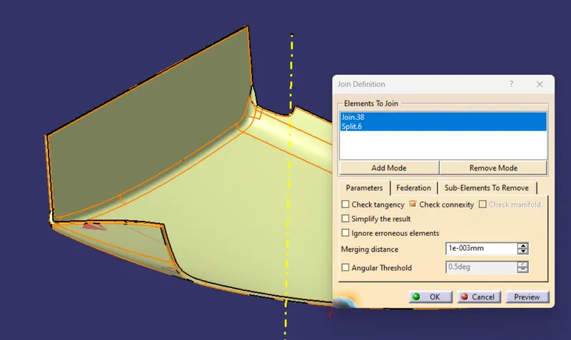
Since there is no open edges, we can proceed to creating solid.
Open part design workbench and click close surface , select the surface body and click ok
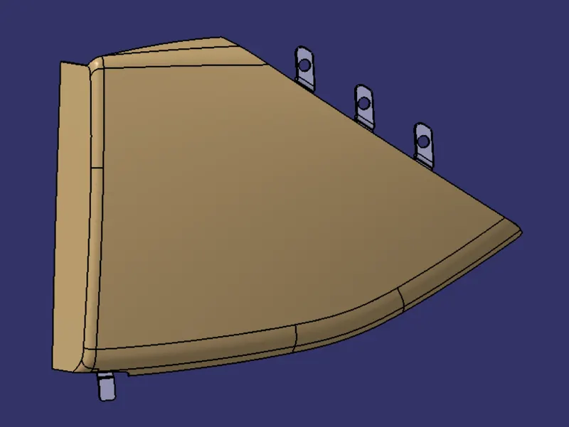
- Draft Analysis
Change the view mode to the custom view and select view paramater as Material mode, then the draft analysis is enalbles.
Click the draft analysis option  , move the compass with the red dot to align with the tool axis.
Now lock the compass and click anywhere on the part, the color will be changed.
The green color shows that the surface satisfies the draft angle and other color if the angle is not satisfied. This can be corrected by altering the angle and measuring at points to get succesfully draft to get satisfied.
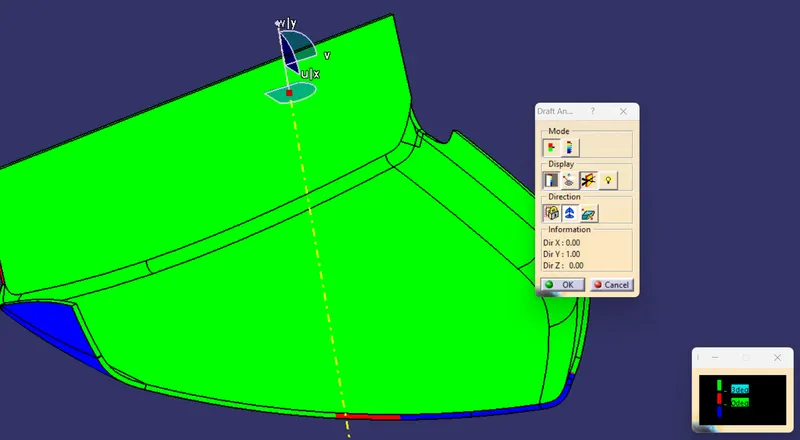
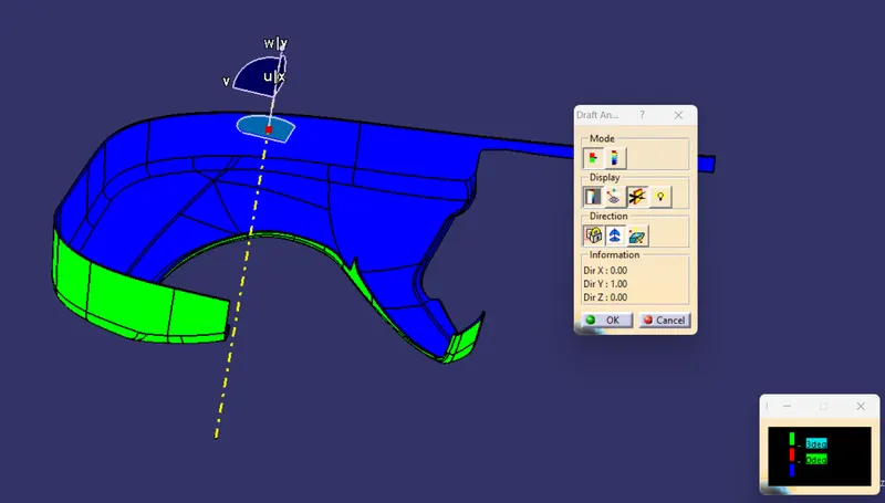
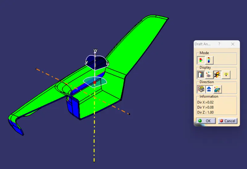
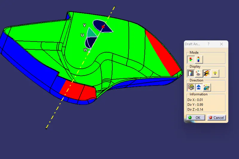
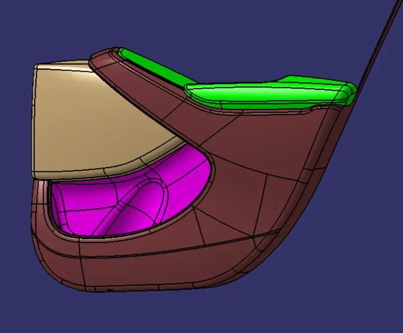
Now since the door trim components are created, the attactment features like heat stake, dog house and clamps are created with the help of master section.
Creation of Heat Stakes:
These heat stakes will enter the mating component and using a heat staking machine these heat stakes are melted and cooled. When cooled this will get hardened and the two components will stick together. Thus all degrees of freedom are arrested.
Creation of Dog house:
The below image show the dimensions of the dog house.
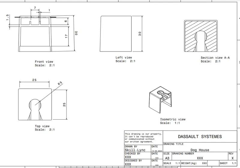
With the help of this image and master section, the whole Dog House attachment is created.
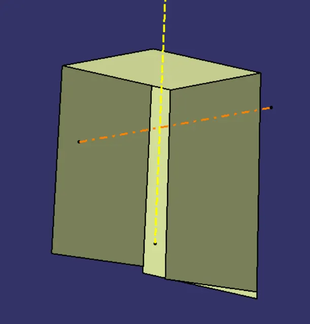
Thicken the suraface.
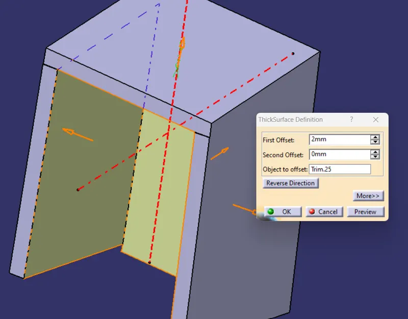
Create the ribs as per the given dimensions and appropriate thickness.
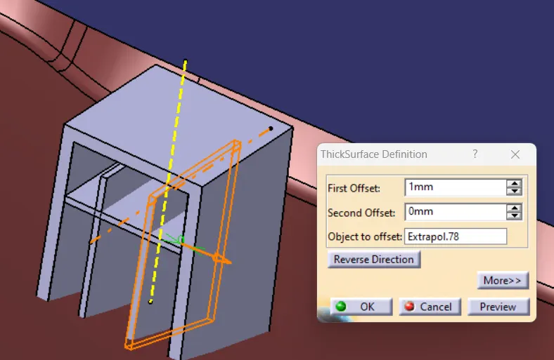
Perfrom union trim operation to remove the excess rib from the main dog house body.
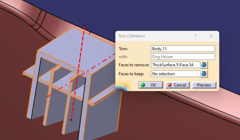
Create surface at the bottom and using split command, split the body as below.
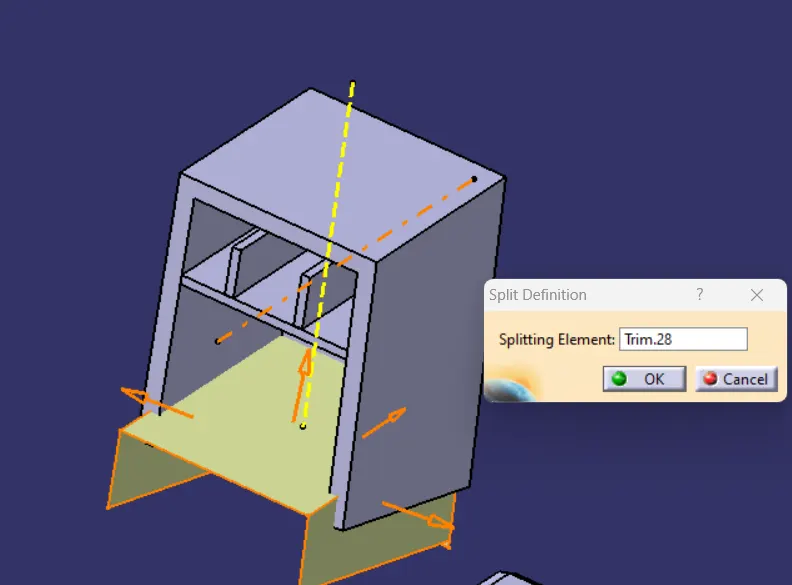
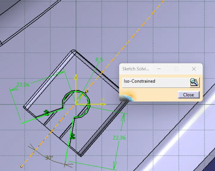
Now we have to create the slot at the top surface.
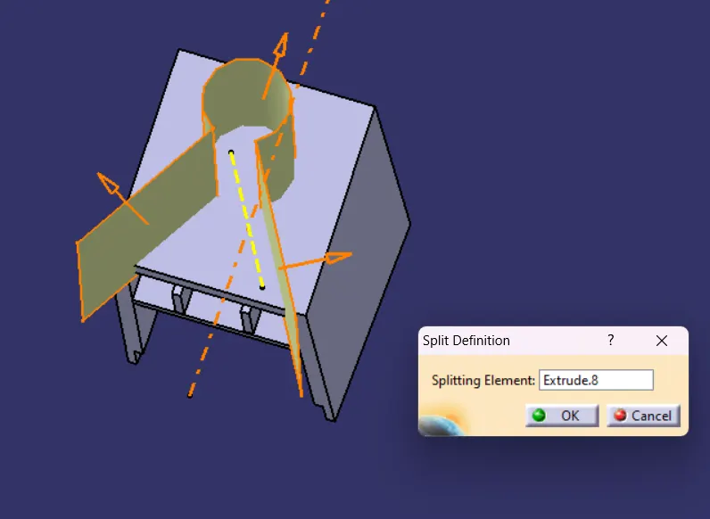
Now again split the body using the extruded surface.
Now apply fillet to the appropriate edges and Attach the dog house to the lower substrate using union trim.
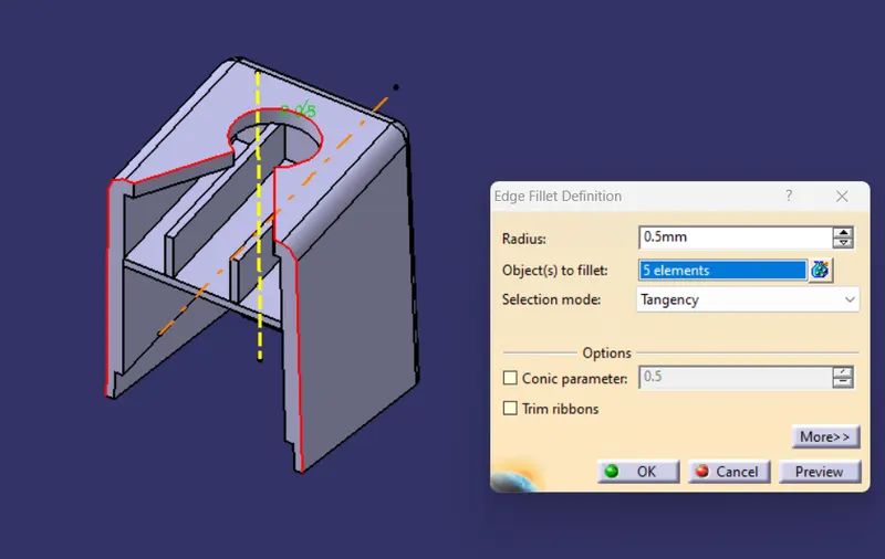
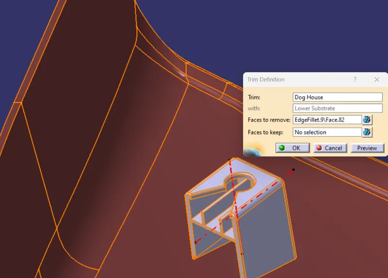
Create a lifting axis and side axis for the dog house as shown in below image.
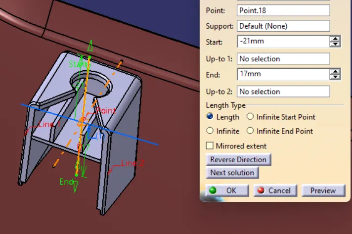
Similarly the flanges are created as per the master section and also at different location as required for the fitment of the components.
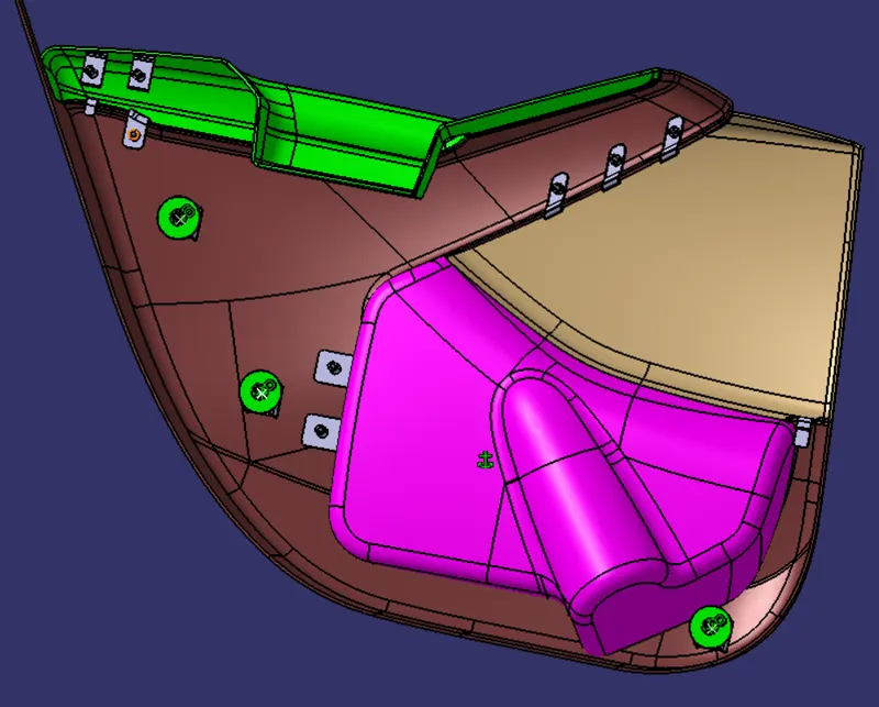
Push pin is assemble with each dog house as above.
Final draft analysis on the above components along with the attachments are caried as shwon below.