Week 11 - Final project
Side Door Plastic Trim
An interior plastic component attached to the inner side of the door. This product improves the appearance of the vehicle intertior and also creates a more comfortable interior by providing a variety of fitments and functions
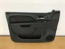
The designers will work on the input Class A surface which are validated from the feasibilty team
The procedure followed in creation of the plastic New Product Design are
i, Tooling axis
ii, B Surface Creation
iii, C Surface Creation
iv, Closed Body Creation
v, Draft Analysis
PROCEDURE OF PART CREATION:
1) Input Given:
Design of Interior Door Trim:
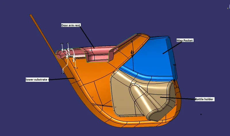
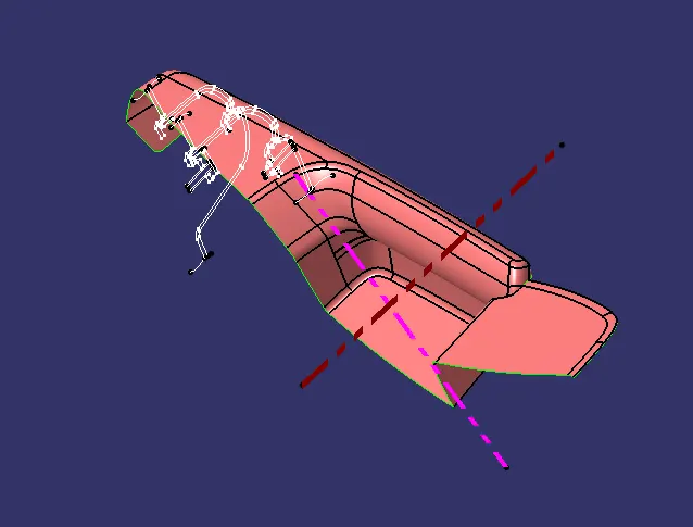
2. Tooling Axis :
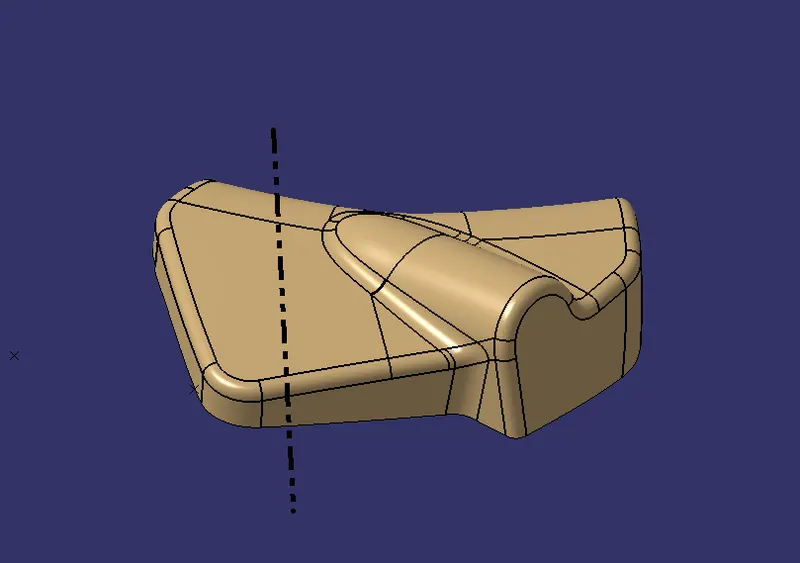
Bottle holder
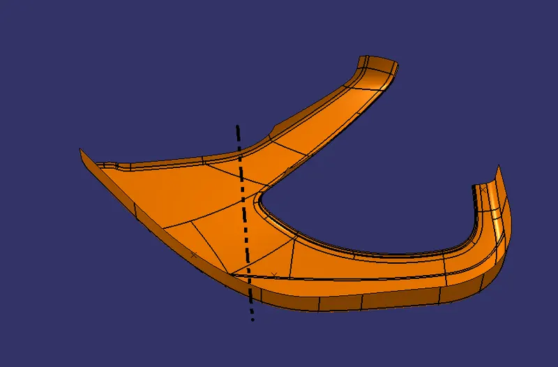
Lower substrate
Map pocket
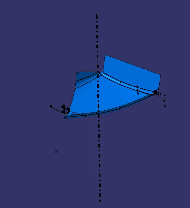
Door Arm Rest
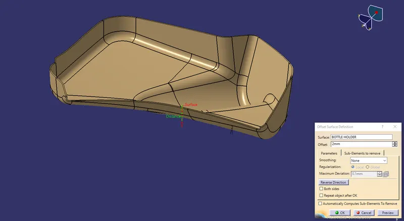
Class B
Bottle holder
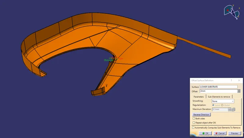
Lower Substrate
To Spllit the unwanted faces
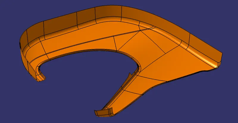
Map Pocket
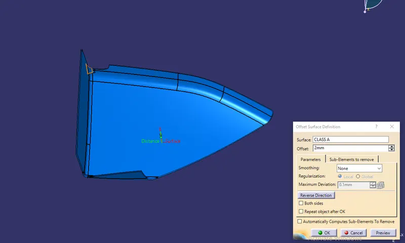
Covered Patches and offset
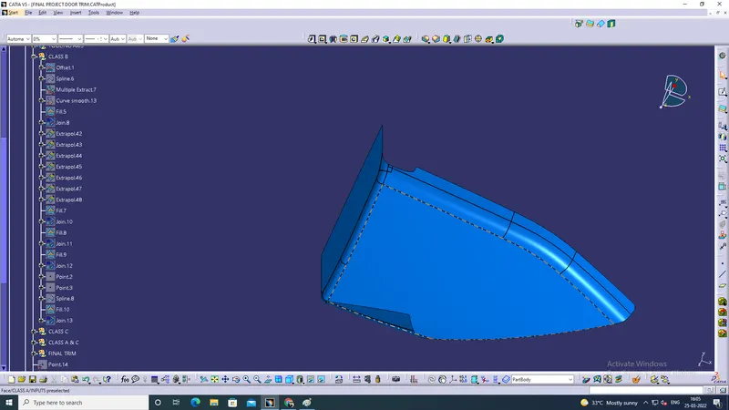
Door arm rest
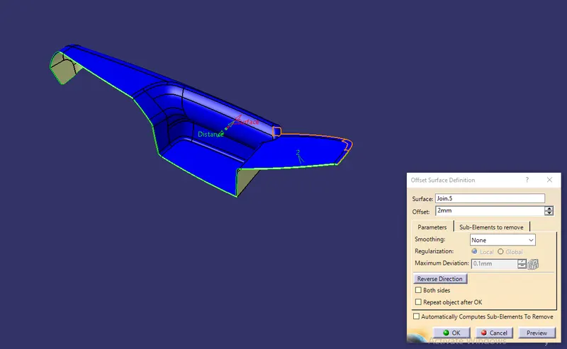
Covered Patches and offset
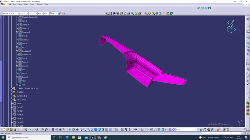
Class C Surface - use boundary and extrapolate the edges and intersect for trimming purpose and join to create c Surface
Bottle Holder
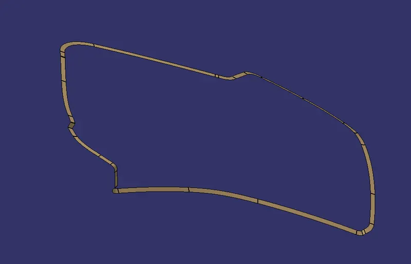
Lower Substrate - use boundary and extrapolate the edges and intersect for trimming purpose and join to create c Surface
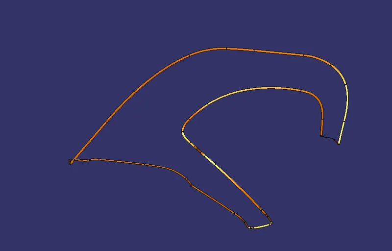
Map Pocket - use boundary and extrapolate the edges and intersect for trimming purpose and join to create c Surface
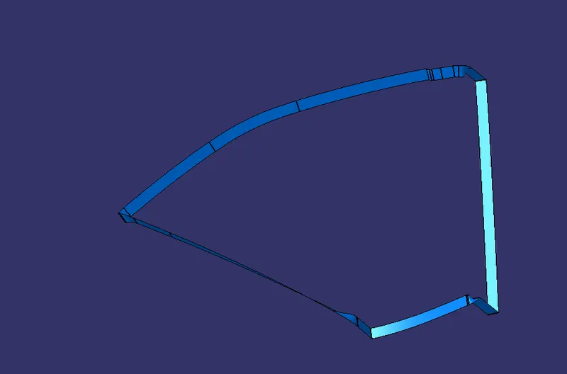
Door Arm Rest - use boundary and extrapolate the edges and intersect for trimming purpose and join to create c Surface
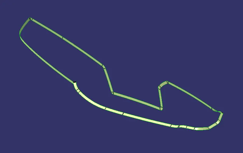
Closed Surface
Bottle Holder - Join A and c and Using trim tool for AC and B to create the closed surface. Then create the new body and represent name given and then using close surface tool to be solid body.
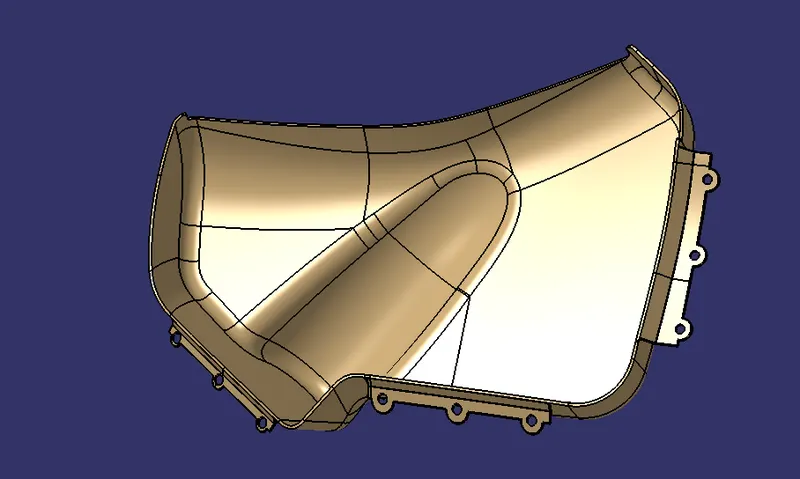
Lower Substrate - Join A and c and Using trim tool for AC and B to create the closed surface. Then create the new body and represent name given and then using close surface tool to be solid body.
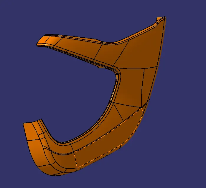
Map Pocket - Join A and c and Using trim tool for AC and B to create the closed surface. Then create the new body and represent name given and then using close surface tool to be solid body.
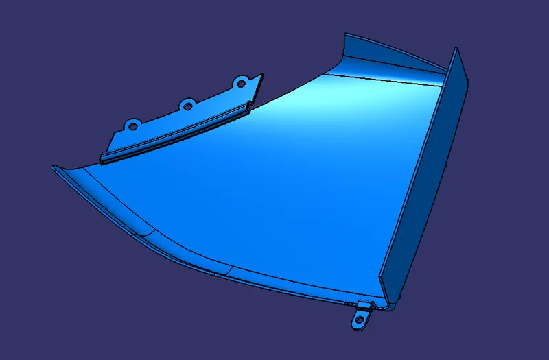
Door Arm Rest - Join A and c and Using trim tool for AC and B to create the closed surface. Then create the new body and represent name given and then using close surface tool to be solid body.
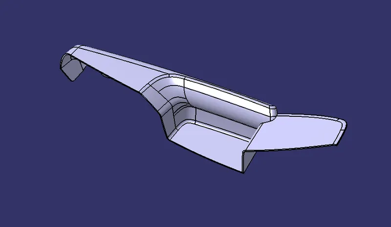
(Note:The Given class A surface all are separately solid then using assembly work bench then pull all solid body for joining purpose)
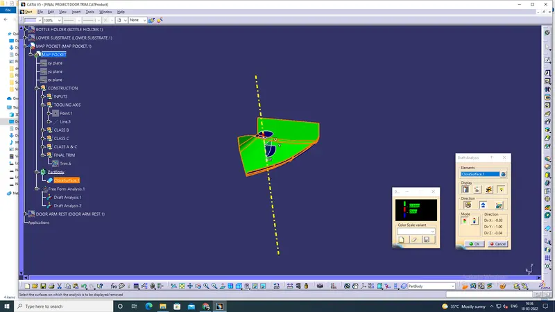
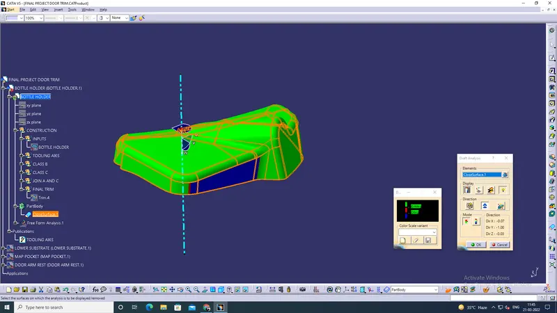
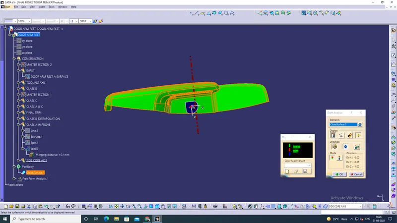
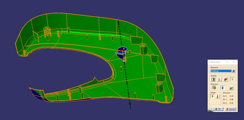
Draft Analysis
Map Pocket
Bottle Holder
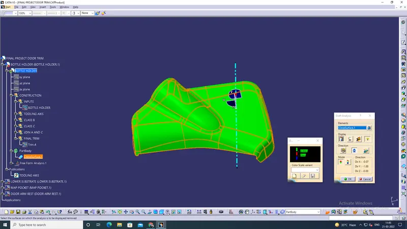
Door arm rest
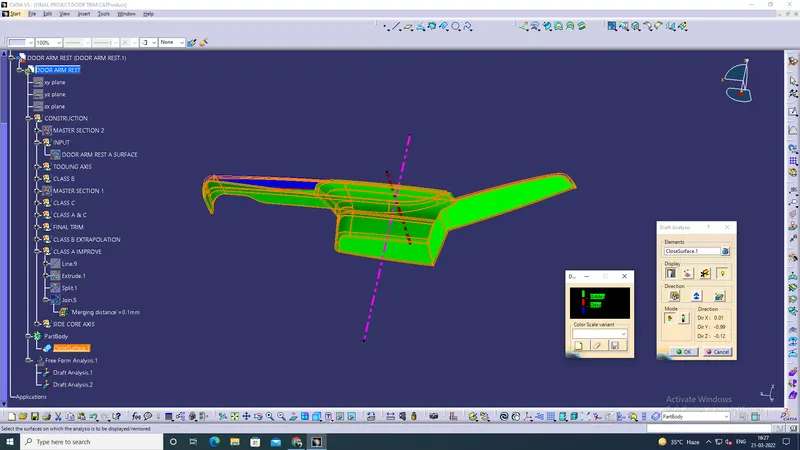
Lower Substrate
B Side Features:
1. Flanges @ Bottle Holder - Take the class A surface and extract the edges and extrapolate, take offset and create the modified sketches and then create the solid body and using boolean operation to assemble the partbody.
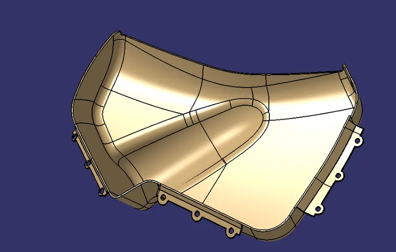
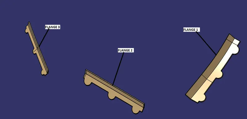
Flanges @ Map Pocket - Take the class A surface for take boundary purpose and extract the given master section edges and extrapolate, take offset and create the modified sketches and then create the solid body and using boolean operation to assemble the partbody.
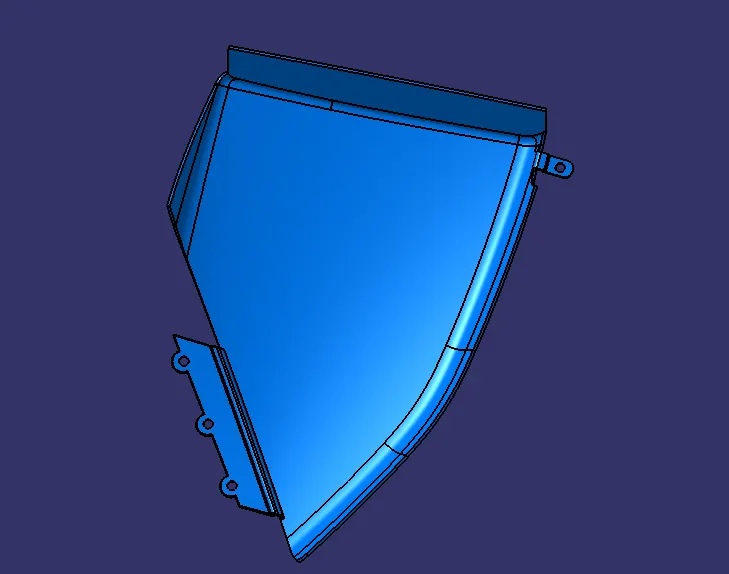
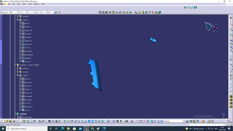
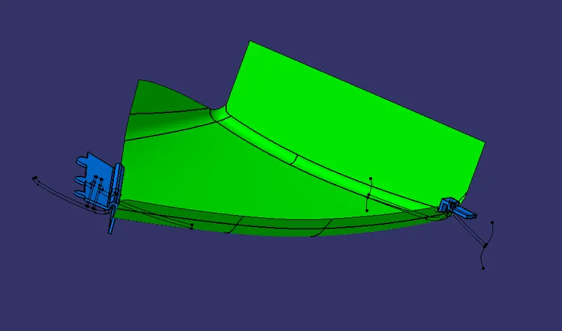
Flanges @ Door Arm Rest - Take the class A surface for take boundary purpose and extract the given master section edges and extrapolate, take offset and create the modified sketches and then create the solid body and using boolean operation to assemble the partbody.
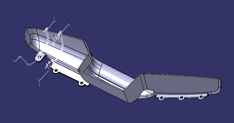
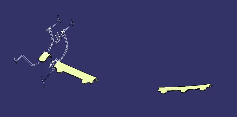
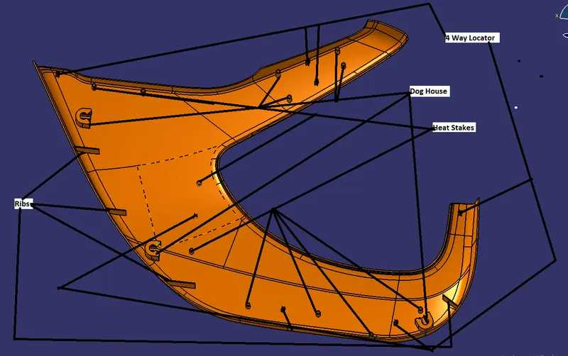
2. Heat Stakes, Dog House ,Rib, 4 Way locators @ Lower Substrate -
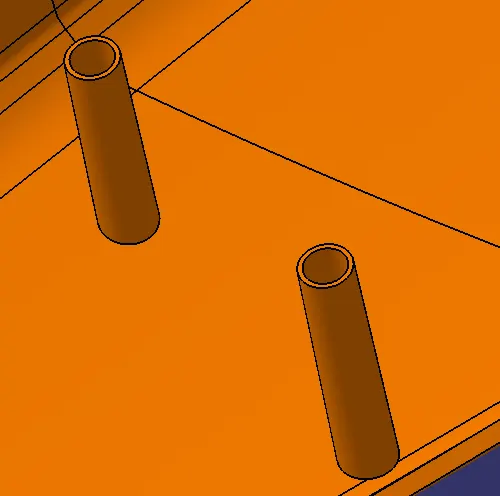
Heat Stakes -
Heat staking also known as thermoplastic staking is the process of joining two dissimilar materials together. In heat staking we use local heating and cooling to raise the temperature of plastic components and allow plastic reforming to be carried out. This reforming can be used in a wide variety of applications
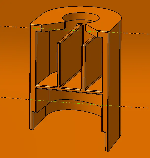
Dog House -
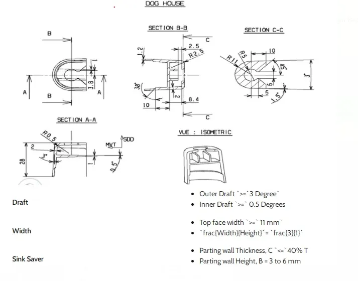
Dog house is an engineering feature used in plastic trim design. Dog houses are used as supporting feature. Sometimes other engineering features like snaps; locators etc. are mounded on them to increase their strength.
Ribs-
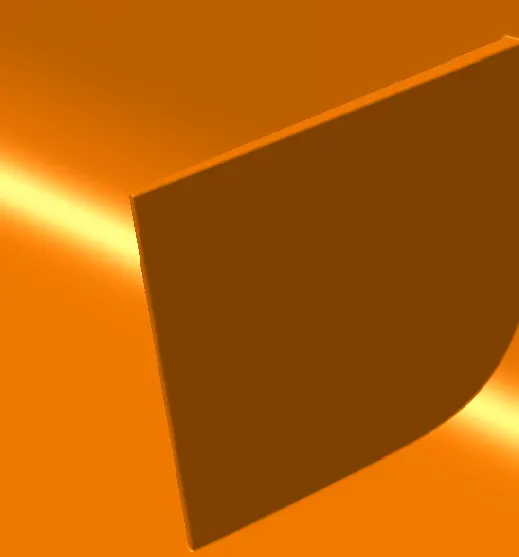
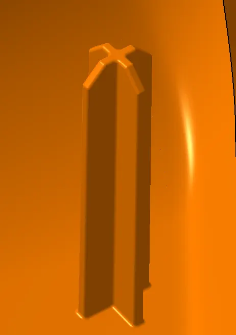
Ribs are thin protrusions that extend perpendicular from a wall or plane to provide added stiffness and strength. Designers commonly try to increase the strength of a part by making its walls thicker.
4 - Way Locator -
A 2-way locating pin restricts motion along 1 axis (or 2 degrees of Freedom), like a round pin in a slot. Likewise, a 4-way pin restricts 4 degrees of freedom along 2 axes. A round locating pin located concentrically in a hole is a common application of a 4-way pin, and helps to further secure the piece
3. Heat Stakes Hole clearance
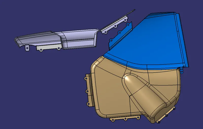
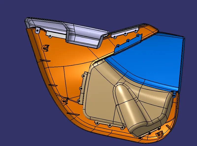
Full Assembly View with B-Side Features
6. Push Pin - The Given Push pin Using assembly bench, then using Coincidence tool to assembly on dog house at right direction.
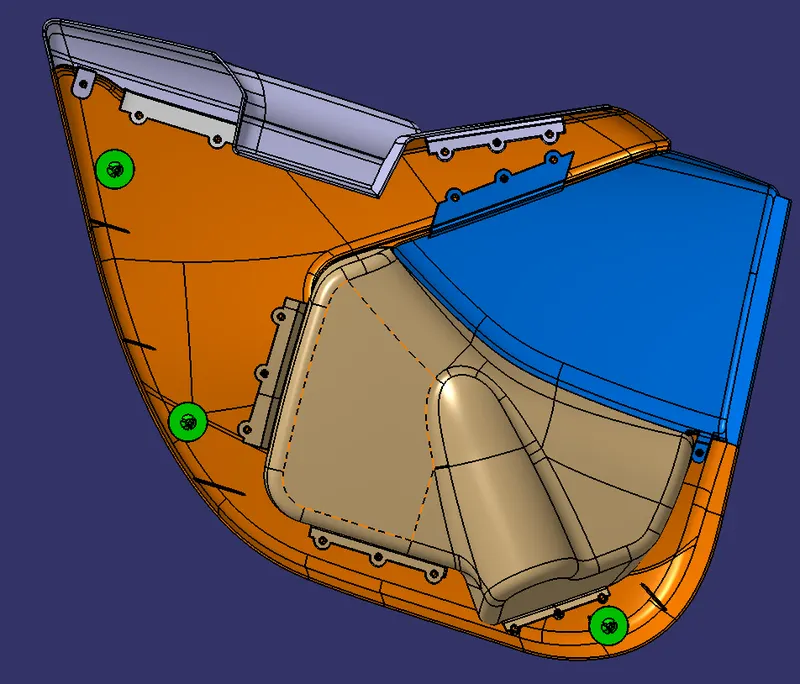
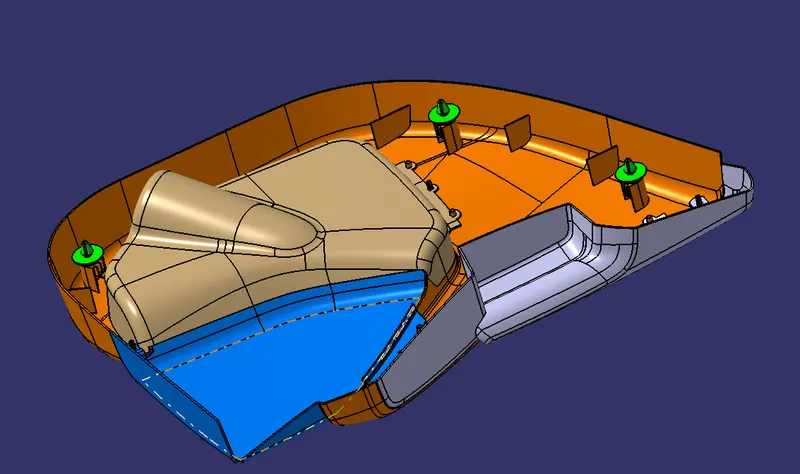
Isomentric, Front, Top & Side
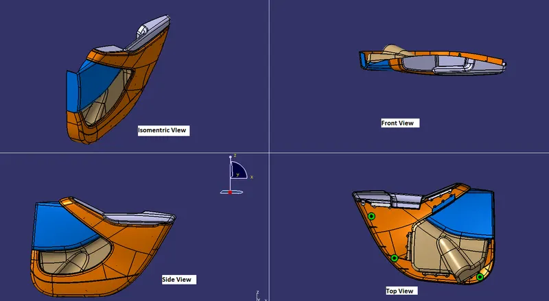
Class A, B and C surface was created as per the automotive standards using CATIA V5 Software.
Draft Analysis was performed for the built model and it could be seen the the draft was under permissible limit for the manufacturing of the component.
B side features were created for the component as per the design Rules.