Week 11 - Final project
DEVELOPMENT OF THE DOOR TRIM PANEL
Till now whatever we have learned right from the beginning of the module to the end each and every concept was more than enough to make us aware about what actually the plastic product designing is about. It has cleared the concepts and gave us the practical knowledge of how actually the OEM’s work in the case of plastic product design.
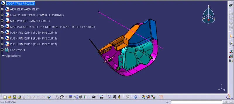
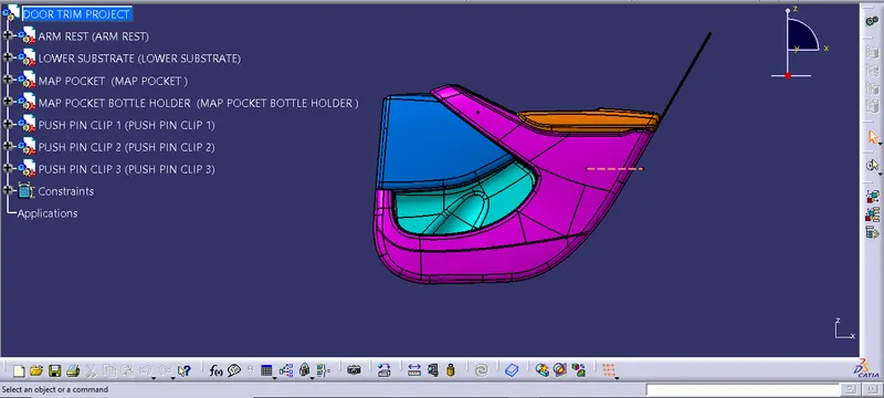
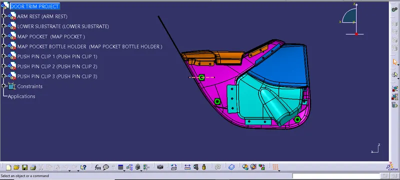
Now to test our knowledge and to check how good our concepts are we are given a final project named the door trim panel along with the masters section. Now our task is to initially analyze all the parts one by one, to study the masters section and then give our output by designing a perfect door trim model along with the engineering features. The door trim model is given as an input along with the master section as shown in the figure below.
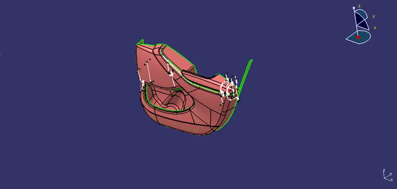
The front side of the door trim.
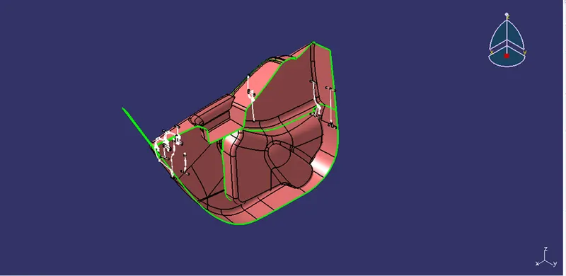
The back side or the inner side of the door trim.
So as we look and analyze the door trim we will come to know that it consists of 4 parts i.e:-
- Arm rest
- Lower substrate
- Map pocket
- Map pocket bottle holder
So now initially our task is to open all this parts one by one into a product/assembly design as shown in the figure below.
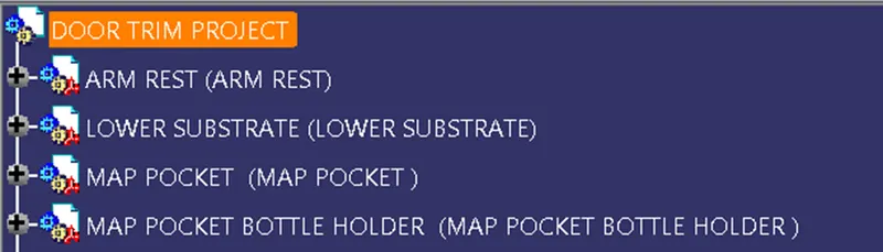
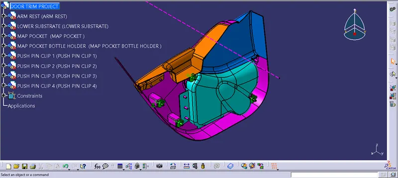
The assembly design is named as the door trim project.
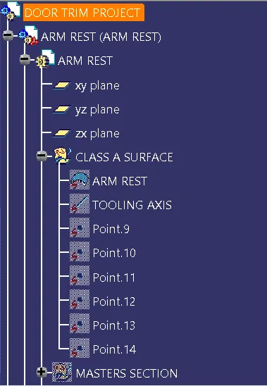
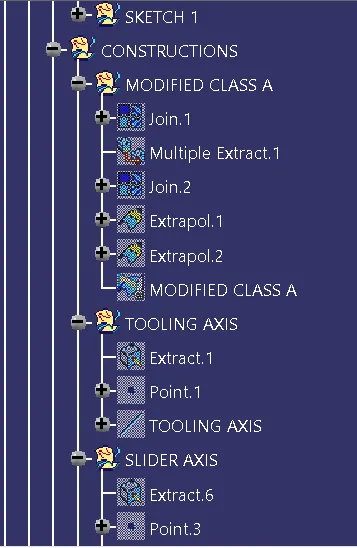
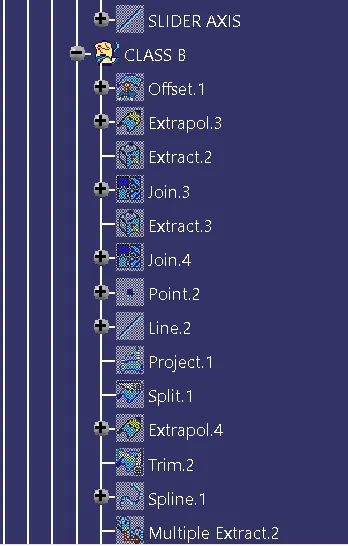
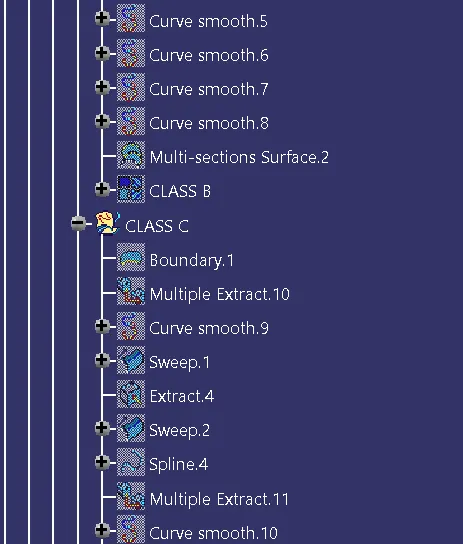
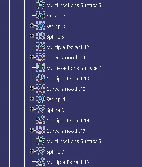
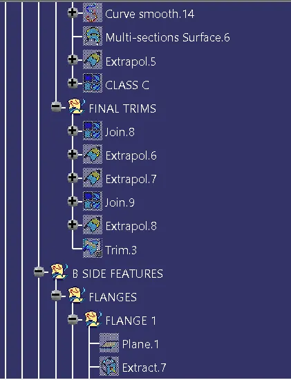
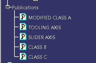
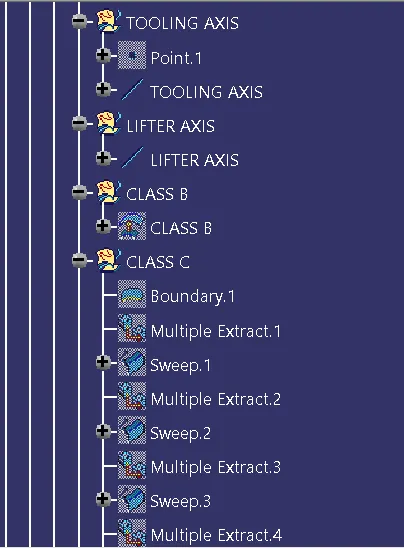
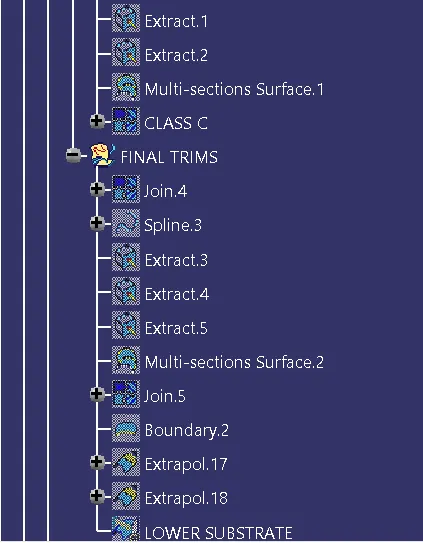
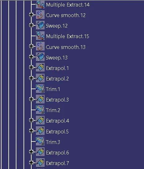
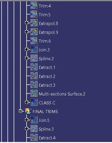
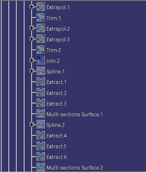
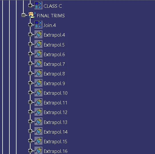
Now let’s start with the first part i.e arm rest. For arm rest as we see the masters section we get that the thickness of the component is 2.5mm. So initially the surface quality is checked weather it is joined properly or not using the boundary or join command. Then the tooling axis designed to check the product is able to manufacture or not. Then the Class B and Class C surface is designed one by one and the final trim is done which gives us the final arm rest product as shown in the figure below.
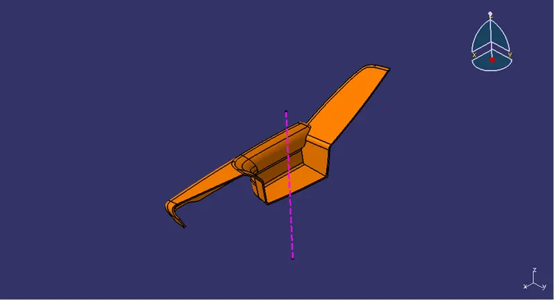
Draft analysis of the arm rest :-
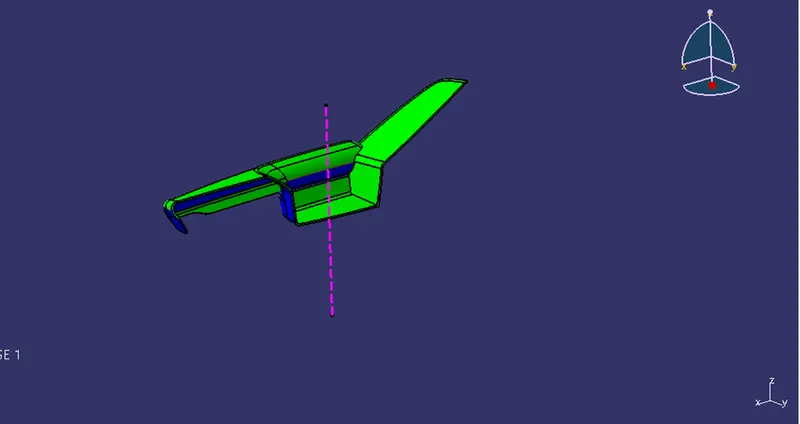
Here to clear the inside tooling of the component i.e the part that is showing the blue color is negative to clear that tooling a slider axis is designed as shown in the figure below.
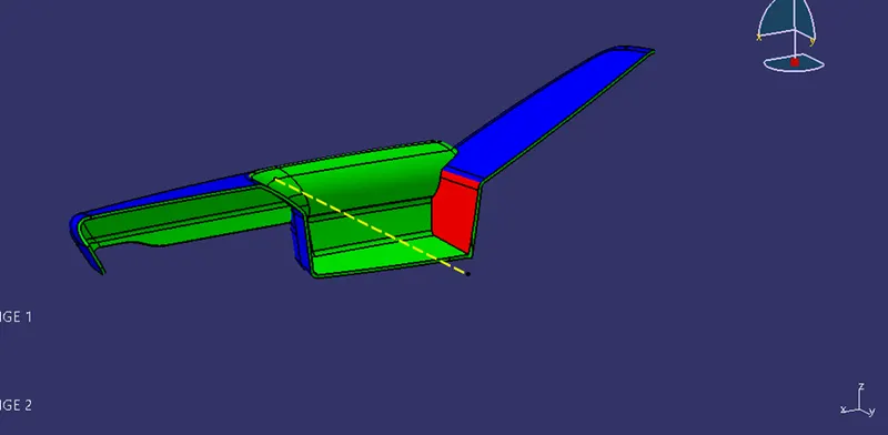
Now we can see the slider axis is clearing the tooling of the inner arm rest.
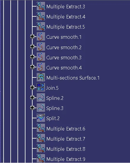
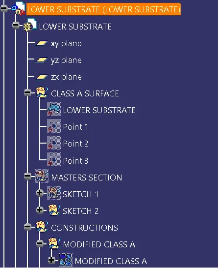
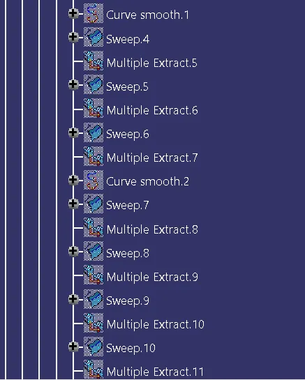
Now the next part that is to be designed is the lower substrate which is the main part of all the door trim panel. So here for the lower substrate initially the surface quality is checked by using the join and boundary command. Then the tooling axis is created to check the component is able to manufacture or not. Then the Class B and Class C Surface is designed, the draft of 3 degree is given to the Class C Surface. Then the final trim is done and then the final lower substrate part is obtained as shown in the figure below.
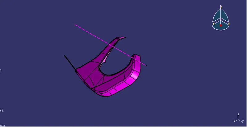
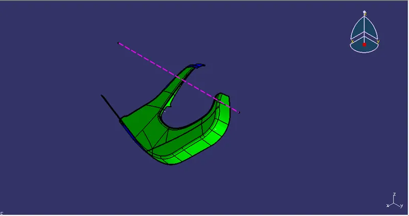
The draft analysis of the lower substrate.
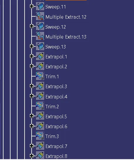
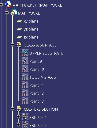
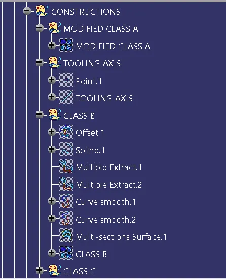
So our next part that is to be designed is the map pocket. In this part initially the surface quality is checked. Then the tooling axis is created in order to check that the component is able to manufacture or not. Then the Class B and Class C Surface is designed and finally the last trim is done and the required component named map pocket is obtained as shown in the figure below.
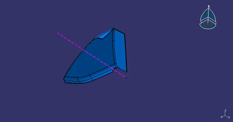
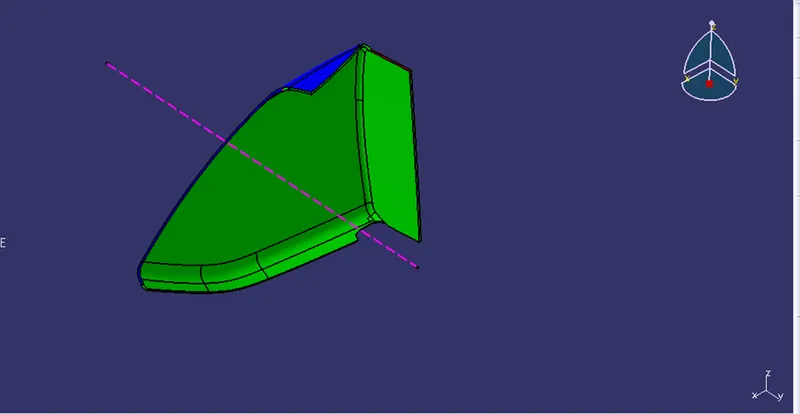
The draft analysis of the map pocket.
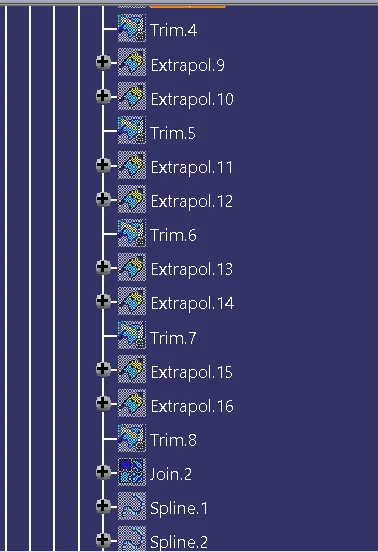
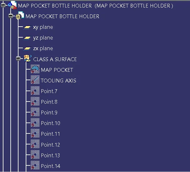
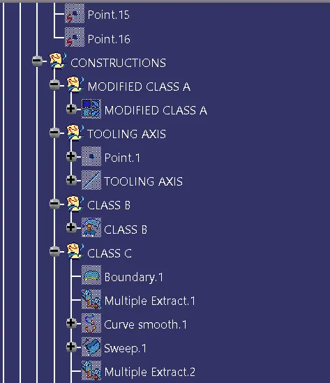
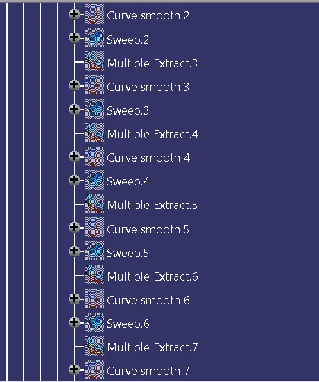
So now our next and the final part is the map pocket bottle holder. For this part the Class A Surface quality is checked and then the tooling axis is designed to checked that the component is able to manufacture or not. Finally the Class B and Class C Surface is designed and then the final trim is provided to the surfaces and the final map pocket bottle holder component is obtained as shown in the figure below.
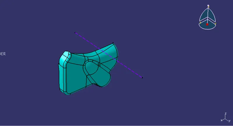
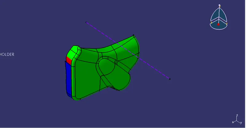
The draft analysis of the map pocket bottle holder.
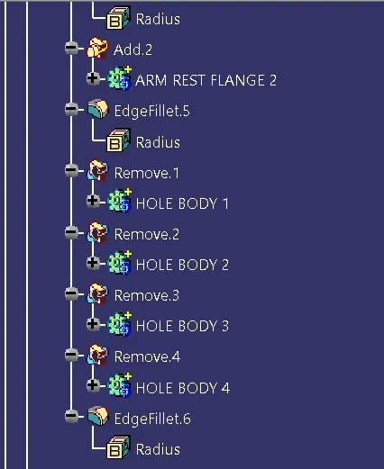
Now as we have provided the thickness to all the components and turn them into the solid body. Our next task is to study and analyze the master section given as an input. So as we observe the masters section we get to know that the flanges are to be designed for each component except the lower substrate because all the component finally be attached to the lower substrate. The flange for the lower substrate will be designed at last.
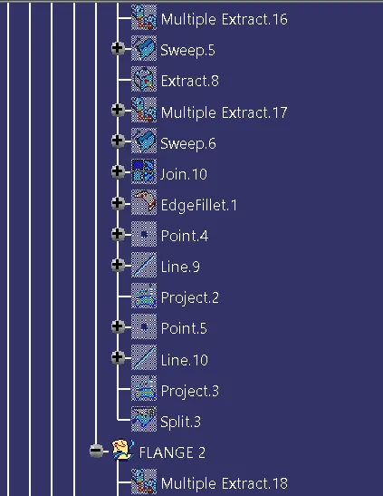
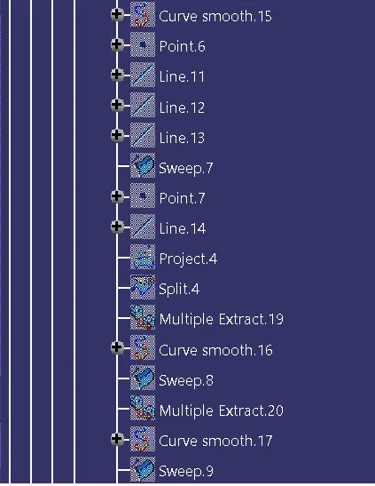
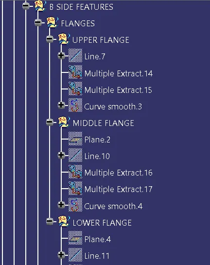
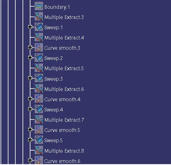
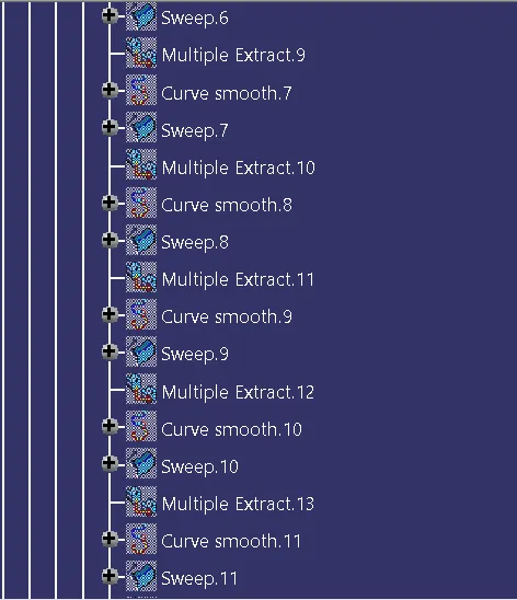
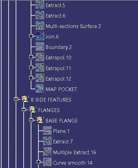
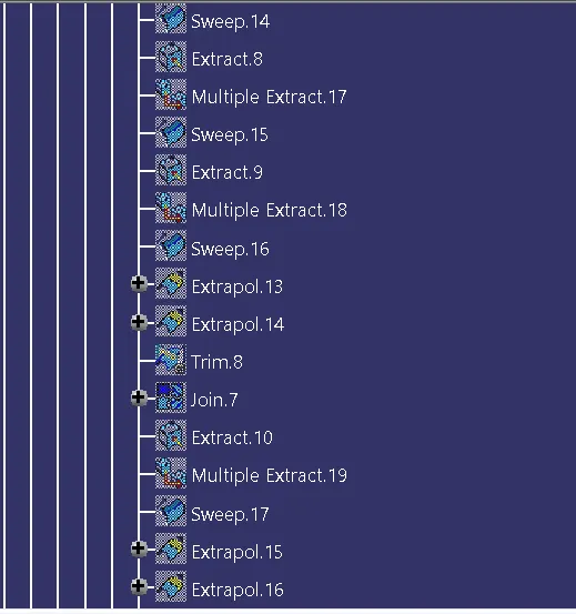
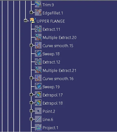
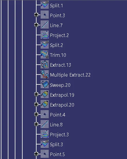
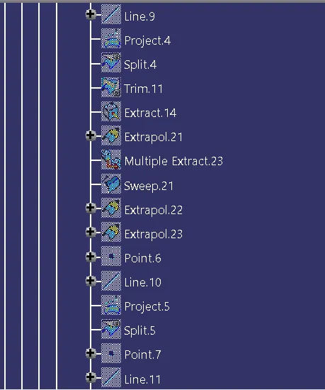
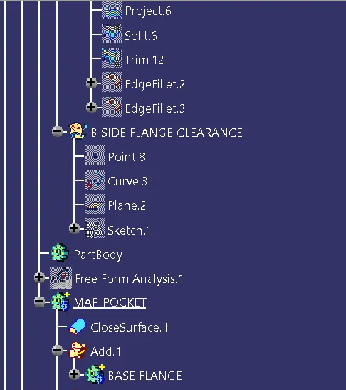
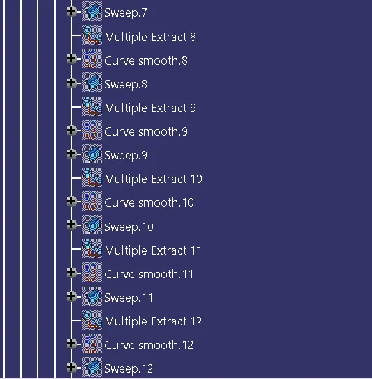
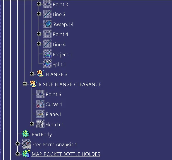
So now to design the flanges initially the arm rest component is selected for the flanges to design. Here the lower part of the arm rest is extracted along with the master section and then sweep is provided to the extracted part.
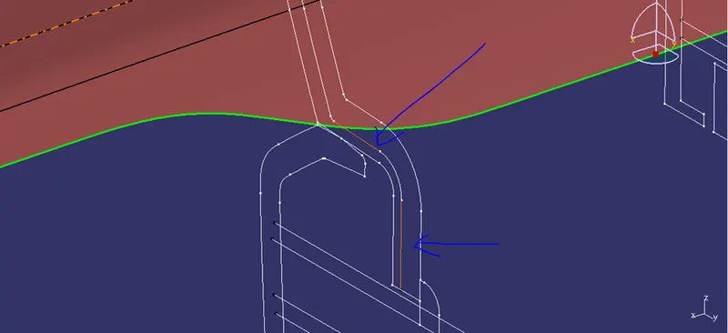
The lines that are marked, the sweep is given in that direction as shown in the figure above.
Then the body is inserted and the thickness is provided to the whole flange body as shown in the figure below.
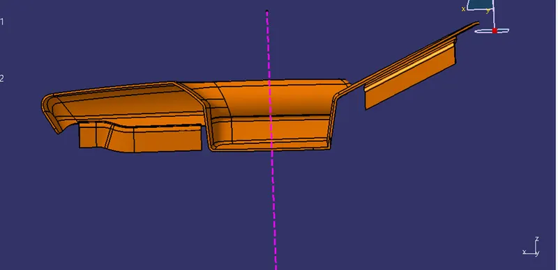
The flanges of the arm rest is designed according to the master section given as an input.
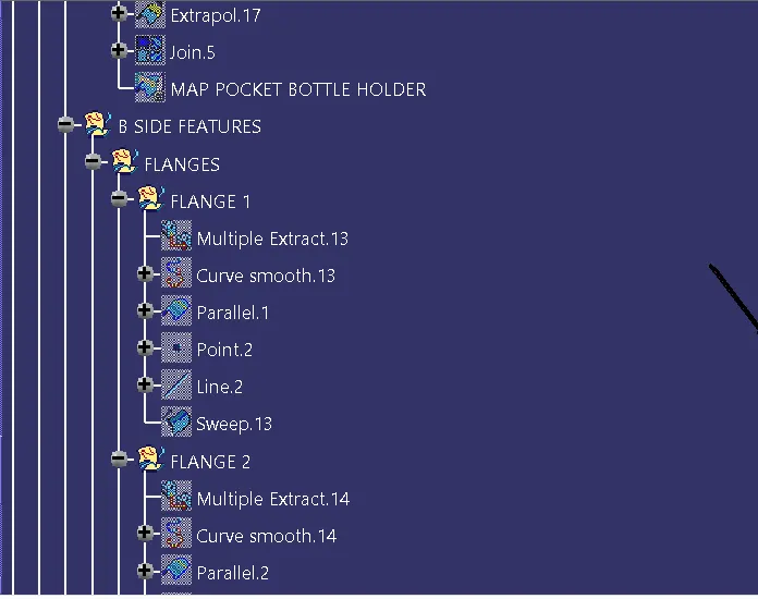
Similarly the flanges are provided to the other parts of the door trim with the same methodology. The purpose of providing the flange is because it provide an attachment feature to the part so that it can get attached to the other parts.
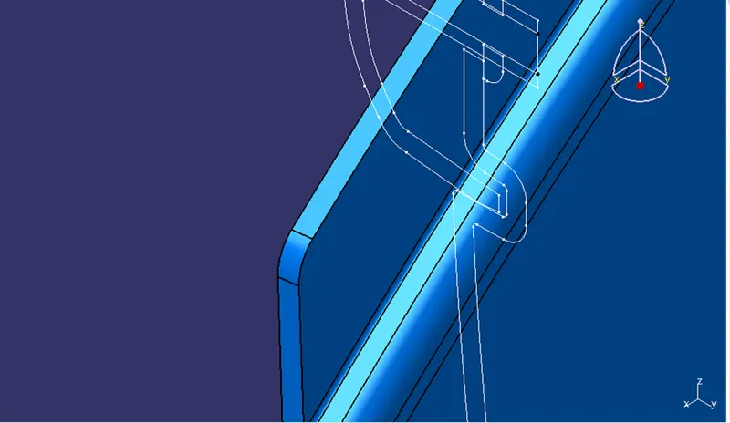
The flanges designed for the map pocket as shown in the figure above.
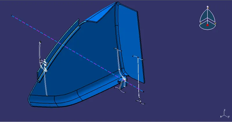
Similarly for the map pocket bottle holder as shown in the figure below.
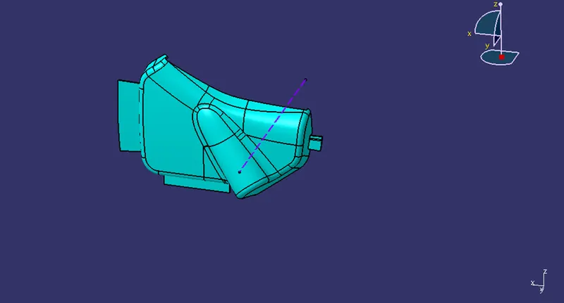
But here the masters section was not provided so here the parallel curve command is used and then the thickness is given to the flanges. The flange thickness according to the master section is 2.5mm.
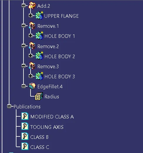
Now all the parts are provided the flanges except the lower substrate. For the lower substrate the masters section is provided but it does not have the even wall thickness, so here the master section is extracted and then the body is inserted and then the rib command is used for the design of the flanges as shown in the figure below.
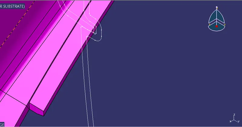
In the above fig we can clearly see that the flange is provided according to the master section.
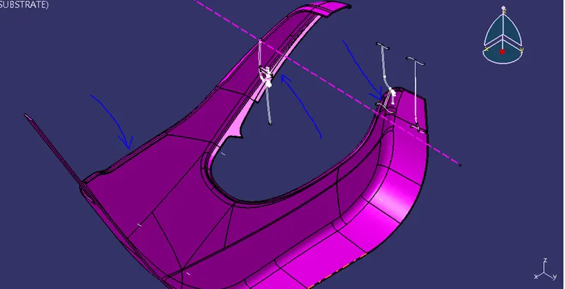
In the above figure the marked places contains the flanges according to the section given.
Now as the first attachment feature i.e the flanges are designed, so now according to the masters section the heat stakes are to be designed in order to join the components together.
So now for the heat stakes as we see the masters section we come to know that all the heat stakes are designed on the lower substrate as shown in the figure below.
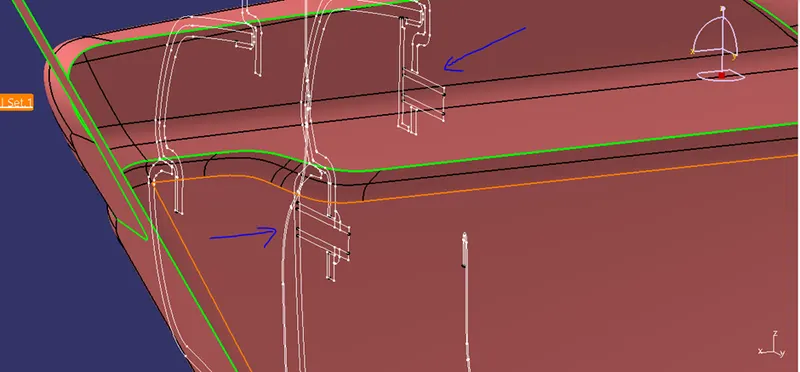
The above marked figure shows that the heat stakes are to be designed on to the lower substrate.
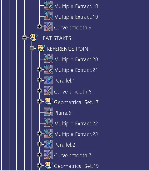
So now the reference points are created, for that the surface is extracted then the boundary of the surface is extracted then the parallel curve option is used to drag the line vertically downward and then the lines and point repetition command is used and the points are marked. Each heat stake should have the minimum distance of 50mm between them. So taking the design rules into consideration the reference points are marked as shown in the figure below.
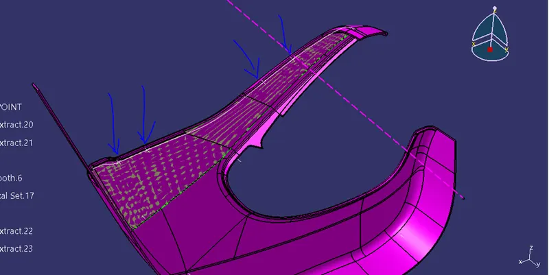
We can see in the above figure similarly the same reference points are given to the different place on the lower substrate as shown in the figure below.
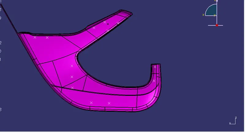
Now the sketch for the heat stake is drawn with the inner diameter as 6 and outer diameter as 8 as shown in the figure below.
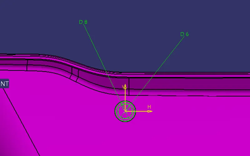
Then it is given the pad of 24mm above the surface and the draft of 0.5 degree is provided to it as shown in the figure.
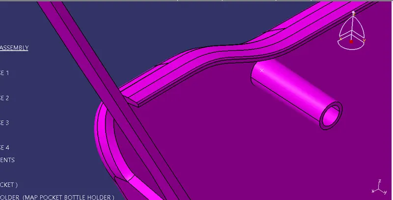
Now this heat stake is copied and is paste special with result link and is translated all along the reference point as shown in the figure below.
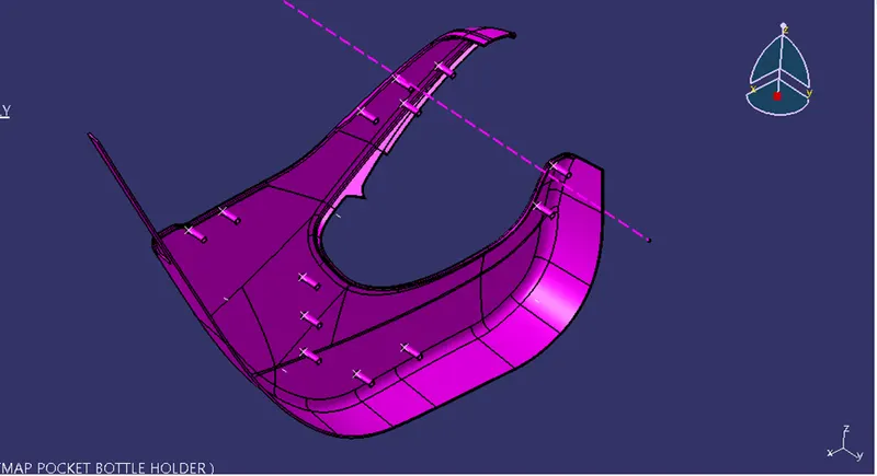
Reference points along with heat stakes.
Now as all the heat stakes are designed, the clearance must be provided to the flanges of the parts. So for the clearance a point is drawn and the circle with the diameter 9 is drawn as the clearance for the heat stakes required is 0.5mm as shown in the figure below.
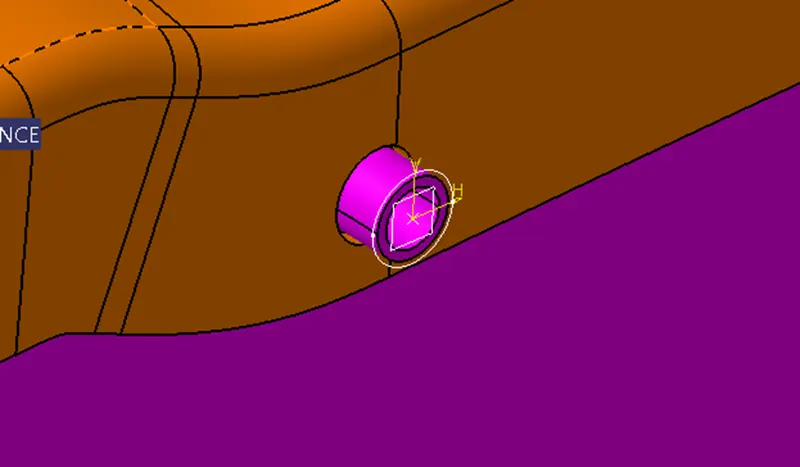
Then it is pad and is removed from the main body in order to provide the clearance to heat stakes as shown in the figure below.
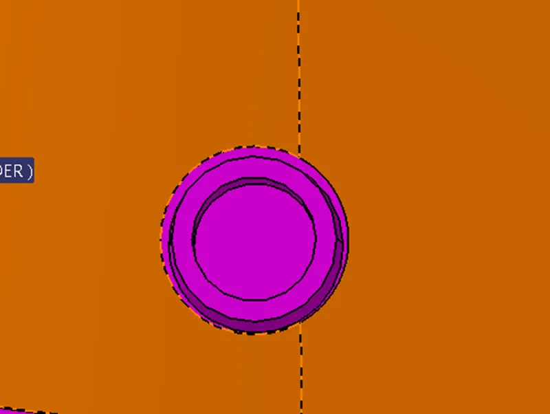
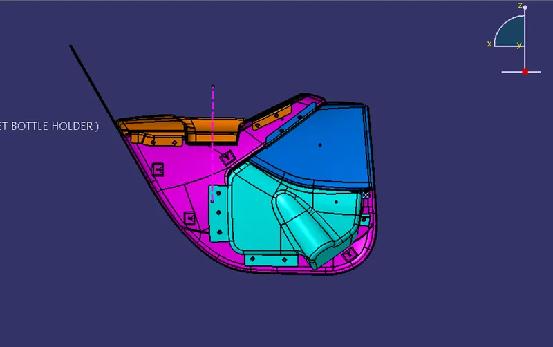
Now as we have created the flanges and the heat stakes we need to create the dog house in order to provide the attachment feature of plastic body with the sheet metal body with the push clips.
So now for the dog house initially the point is located on to the lower substrate and then the line is drawn vertically which we called it as the reference line. Then the design of the dog house is made using the required dimension as shown in the figure below.
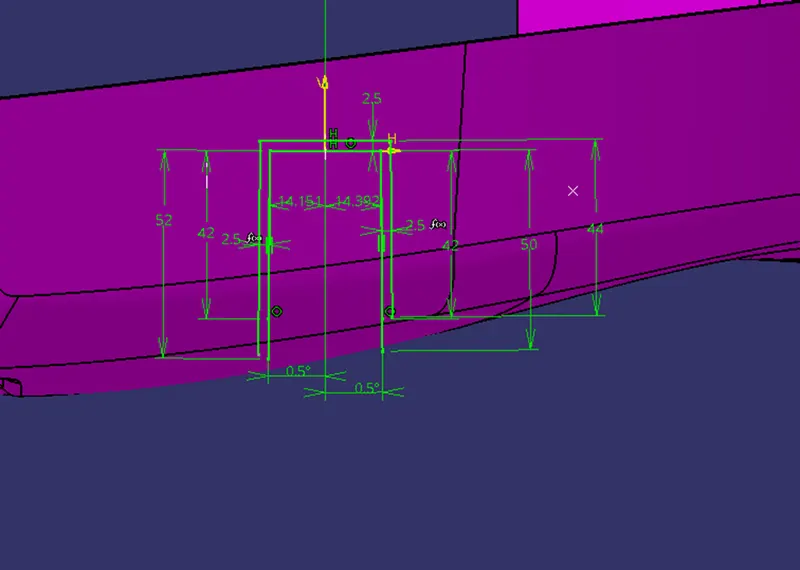
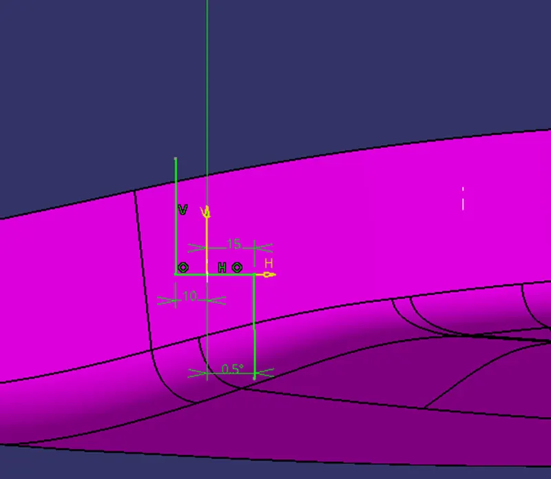
After extruding and trimming the surface we get required surface as shown in the figure below.
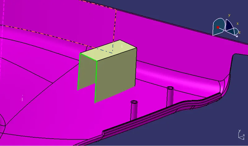
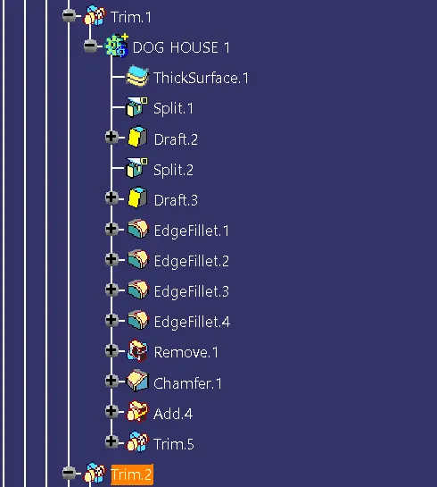
Then the surface is provided the thickness of 2.5mm and the split is performed as shown in the figure below.
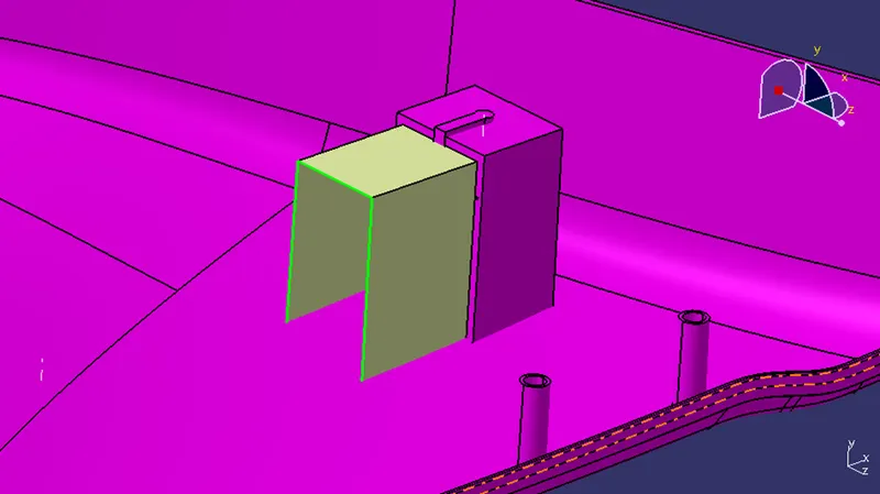
Then the draft of 0.5mm is given to the inner faces and then the lower surface is offset upward in order to create the thin slot at the bottom of the dog house according to the design rule the slot should be from 0.3mm to 0.6mm vertically. So here the slot is 5mm vertically upward. Then the split is provided to dog house which results in creation of the slot as shown in the figure below.
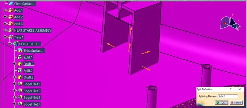
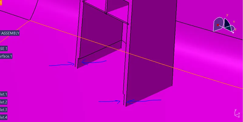
Then the draft of 0.5mm is provided to the inner faces of the lower split as shown in the figure below.
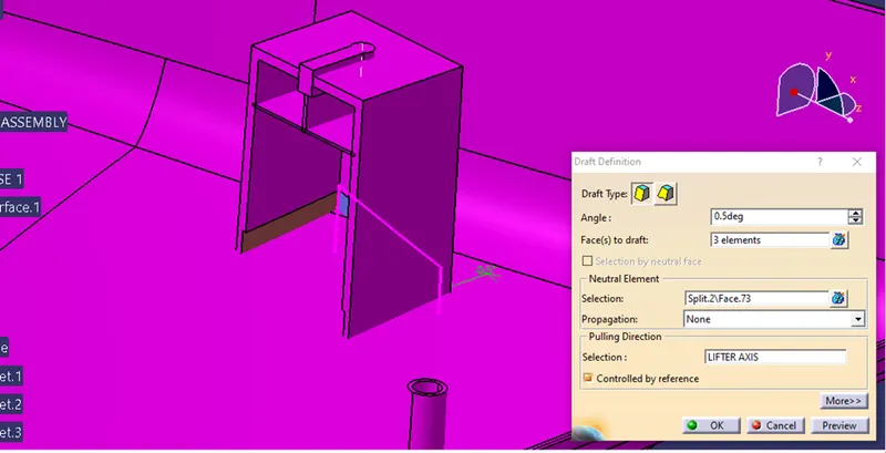
Then the fillets are provided to the dog house as shown in the figure below.
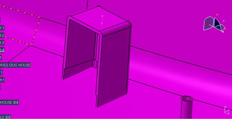
Here the dog house design doesn’t ends we need to create the space for the push clips as it will be the attaching part for two components. So here the plane is created at the top of the dog house and the sketch is drawn as shown in the figure below.
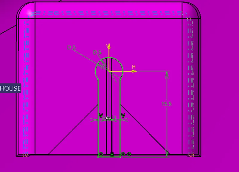
This sketch is then pad and then it is removed from the main body in order to create the slot, as well as the chamfer of 9mm * 45 degree is also given to the dog house as shown in the figure below.
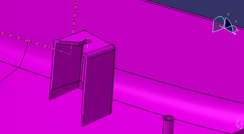
Now to make the structure and design tough and stronger the ribs are added to the dog house and the draft of 0.5mm is provided as shown in the figure below.
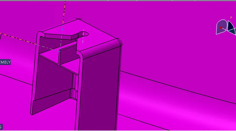
Hence the design of the dog house is fully completed now we need to translate the dog house using the coordinates as shown in the figure below.
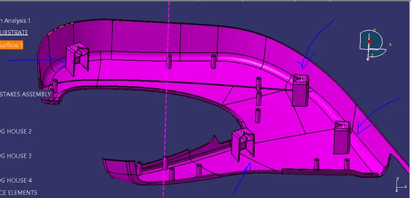
In the above figure the dog house is translated on to the four different places.
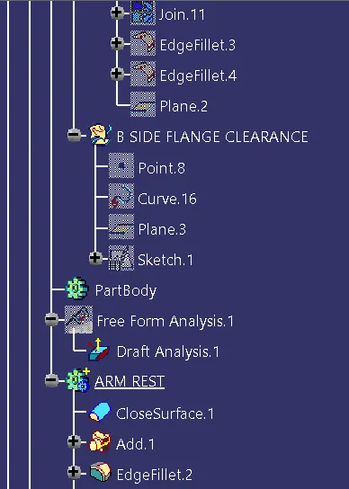
Hence our design of all the parts along with the B side features is completed.
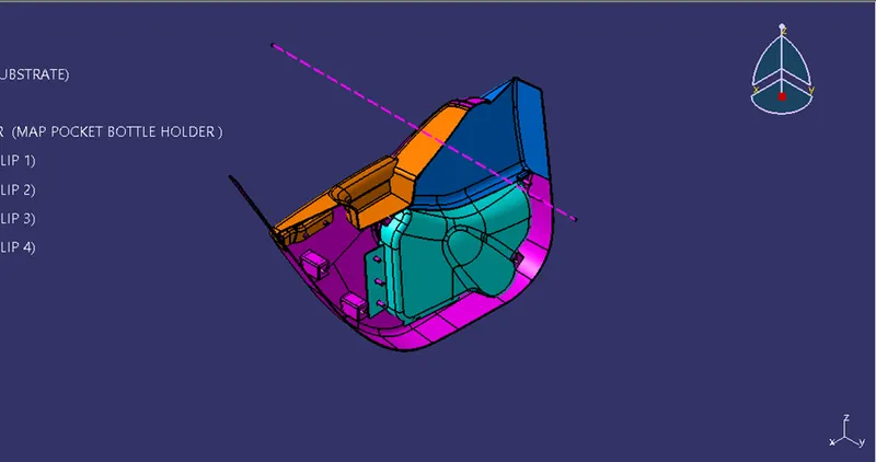
This is how the door trim looks after the design of all the parts.
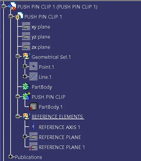
Now our next task is to insert the push clips on to the dog house. Here the push clip design component is given as an input as shown in the figure below.
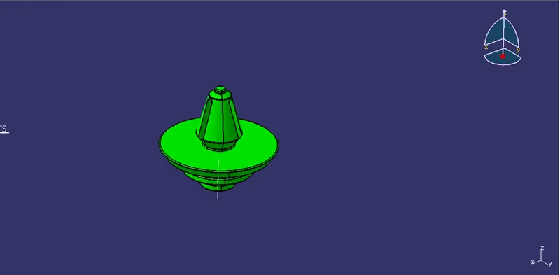
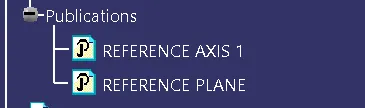
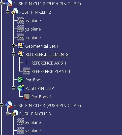
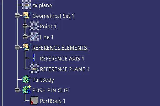
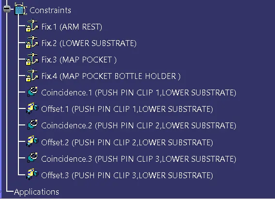
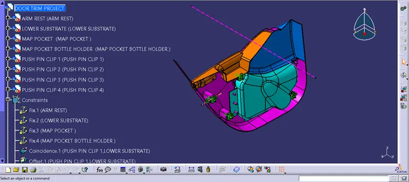
Here the push pin clips are to be mounted on to the dog house. So here initially all the components are fixed as the skeleton reference, then the reference axis is marked at the top of dog house and at the base of the push clips. Here both the reference axis are given the coincident relation and then the offset value of 0.5mm is provided as shown in the figure below.
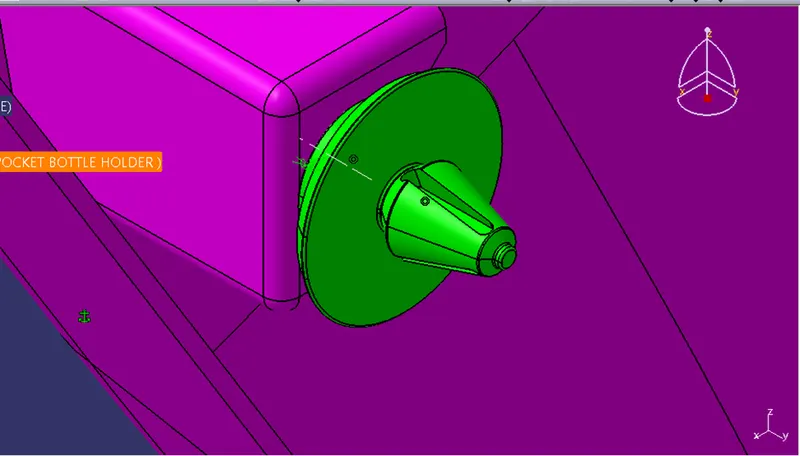
Similarly the same procedure is done for all the other three push pins and our final door trim panel is ready.
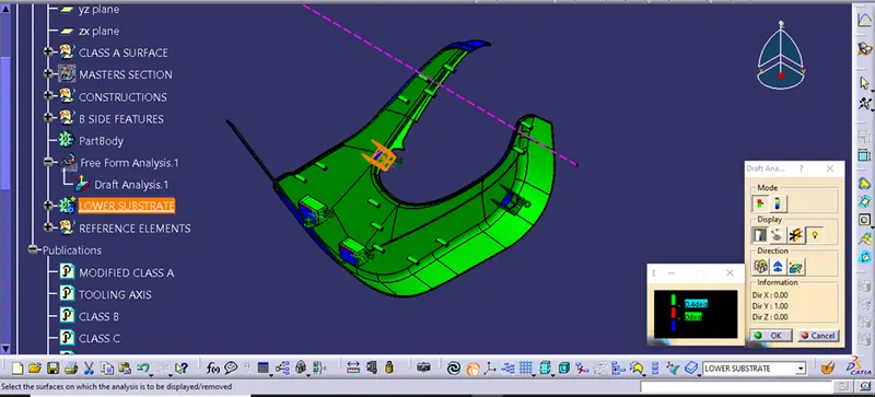
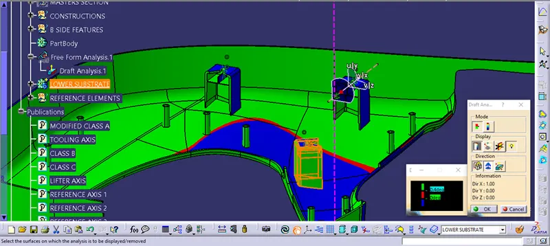
DRAFT ANALYSIS OF THE ENGINEERING FEATURES / B-SIDE :-
- Heat stakes :-
- Dog house :-
Hence the design and the development of the door trim is finally completed.
IMAGES :-