Week 11 - Final project
DEVELOPMENT OF DOOR TRIM PANEL USING CATIA V5
OBJECTIVE: The main objective of this challenge is to create a door trim panel by following the master section and given class A surface. After that we have to design B-side features by following the master section. Finally we have to prepare a detailed report by attaching all the images.
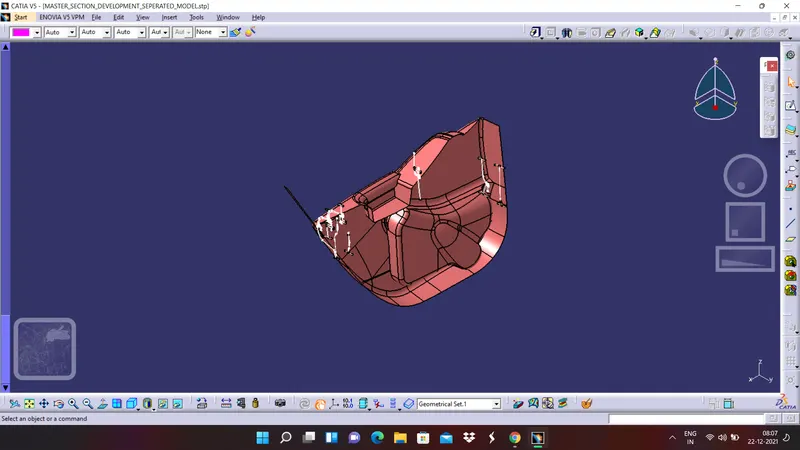
First we will see the given class A surfaces and master sections
1. CLASS A SURFACE:
2. GIVEN MASTER SECTION:
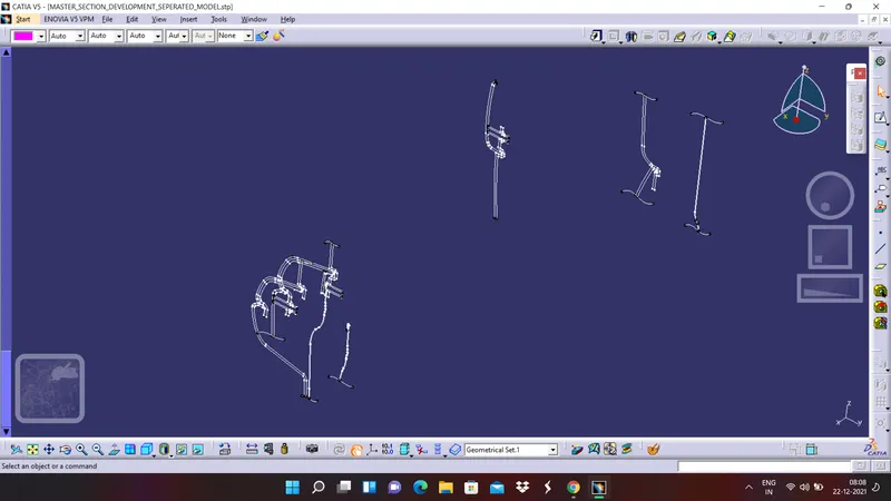
We will discuss the design of individual component and then we will assemble them together,
1. DESIGN OF LOWER SUBSTRATE:
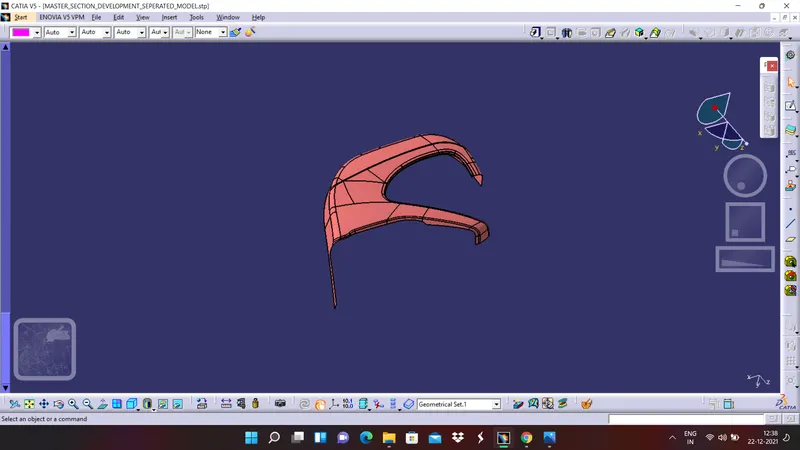
1. The given class A surface for the lower substrate is as shown in below figure,
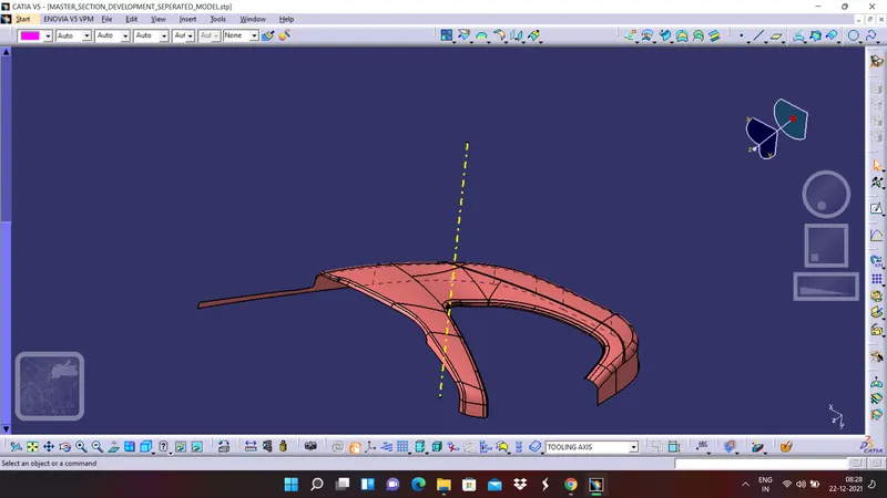
2. We will now create a tooling axis for the class A surface and try to perform draft analysis on it. For creating tooling axis create point on the surface and by using line command try to create a line and name it as tooling axis.
DRAFT ANALYSIS ON CLASS A SURFACE: By using feature draft analysis tool in catia software, align the compass to the tooling axis which we have created and lock the direction. The views of draft analysis of class A surface are as shown in below figures,
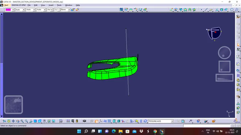
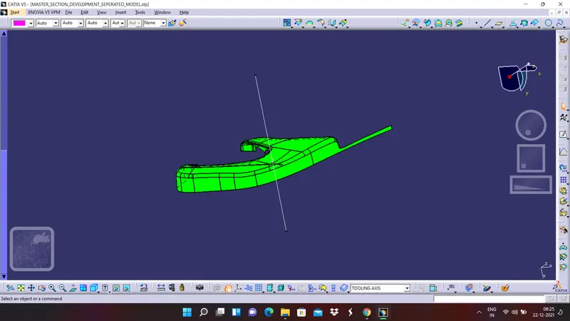
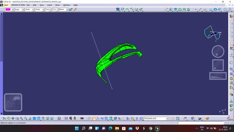
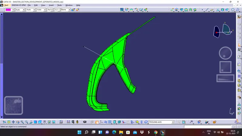
CREATION OF CLASS B SURFACE FOR LOWER SUBSTRATE: The creation of class B surface can be done by simply offsetting the class A surface to the reuired distance and in required direction.
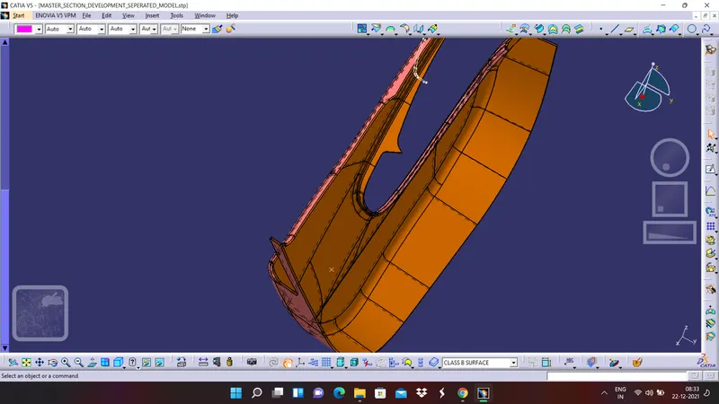
CREATION OF CLASS C SURFACE:
The class C surface is created by sweeping the class A surface with proper direction and angle. Divide the portion of class A into small small boundaries if you want. Finally make sure the C surface is joined properly.
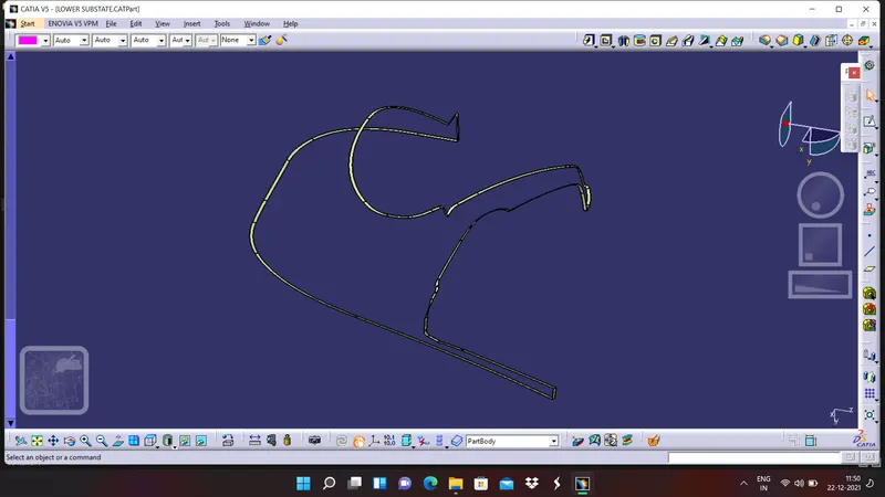
Join class A surface and class C surface
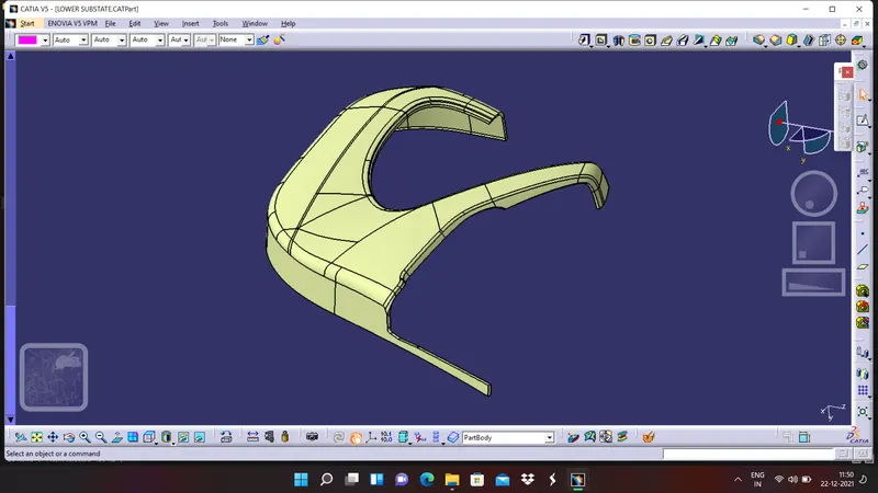
Finallly trim it with class B surface to form a final surface of lower substrate
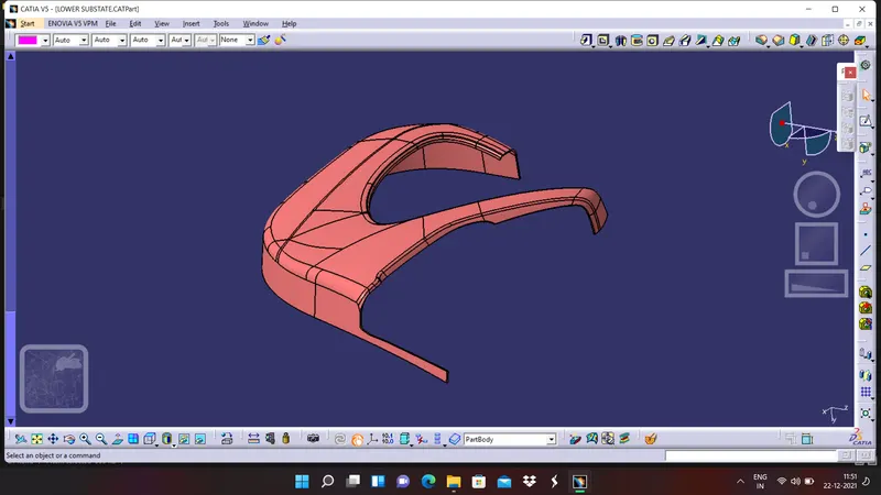
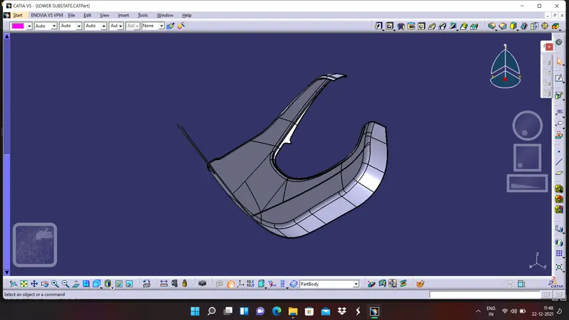
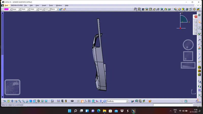
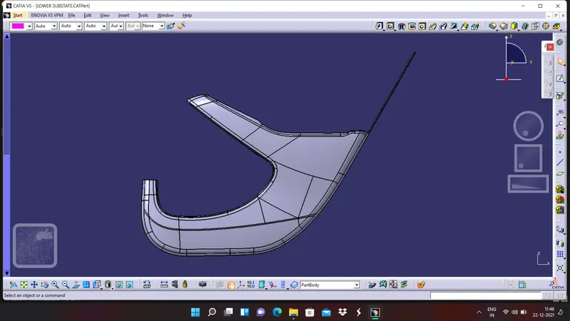
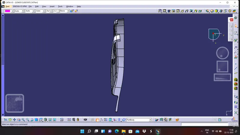
By using close surface command in part workbench, fill the surface and make it into a solid body and the viws of final solid are given below,
ISOMETRIC VIEW
FRONT VIEW
SIDE VIEW
TOP VIEW
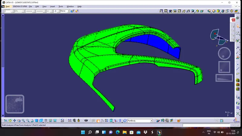
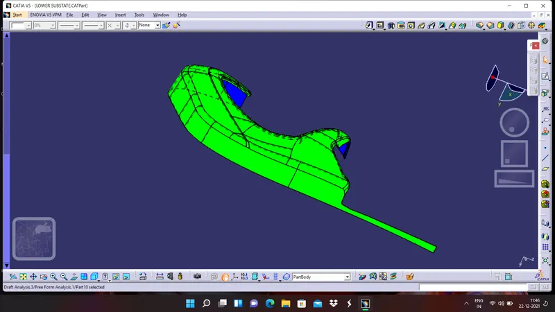
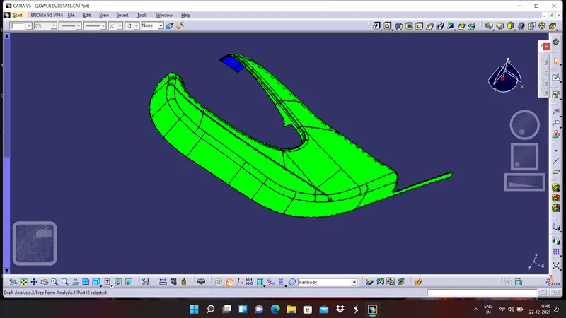
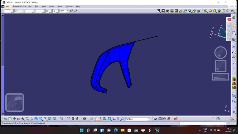
DRAFT ANALYSIS ON LOWER SUBSTRATE:
By using the same tooling axis which we have created for the class A surface perform draft analysis, let us see some of the images of the draft analysis
2. DESIGN OF OUTER MAP POCKET:
1. The image of the class A surface of the outer map pocket is shown in below picture,
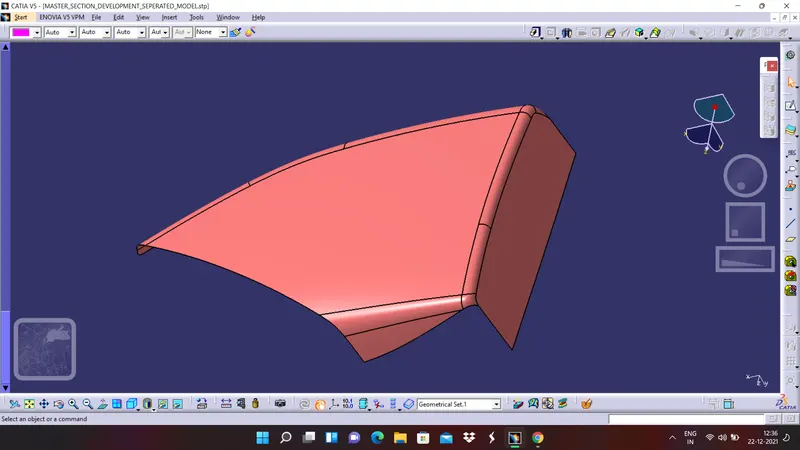
2. We will now create a tooling axis for the class A surface and try to perform draft analysis on it. For creating tooling axis we have to create point on the surface and by using line command try to create a line and name it as tooling axis.
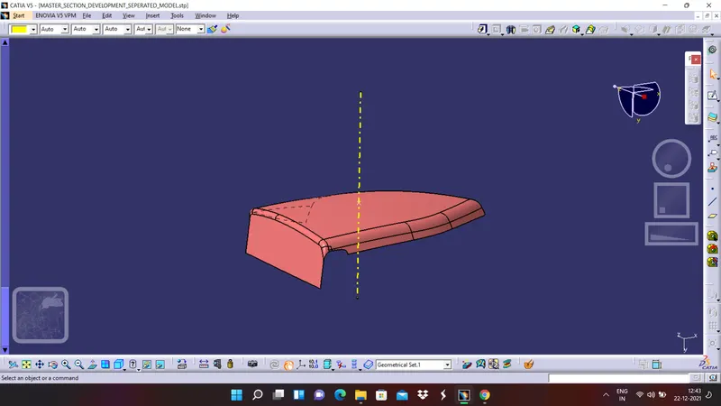
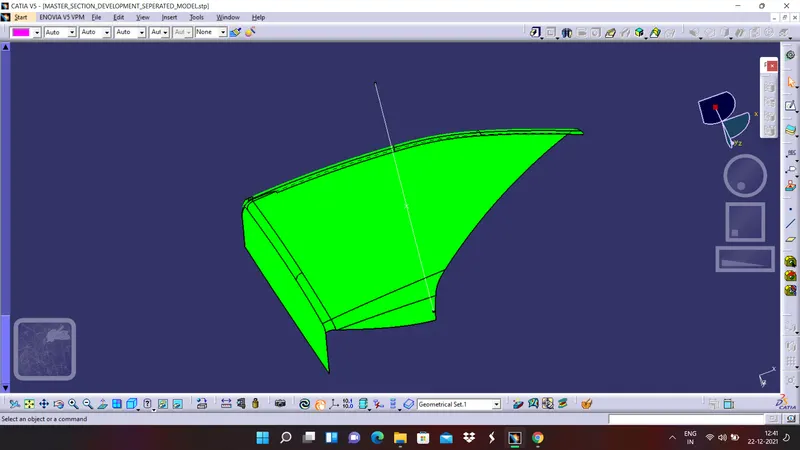
3. Then now perform draft analysis on class A surface, the below images shows the images of the draft analysis,
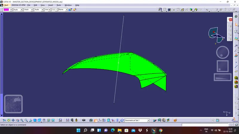
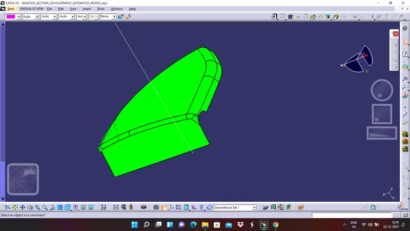
CREATION OF CLASS B SURFACE:
To create class B surface offset the class A surface to the required distance and in required direction measure the thickness of the component in master sections.
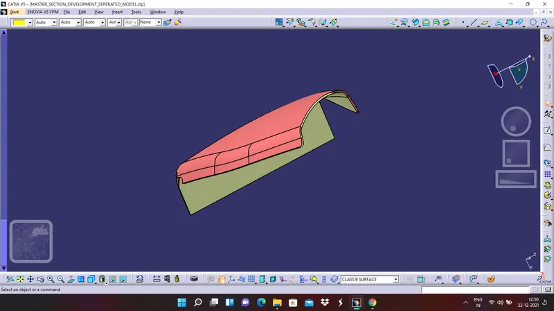
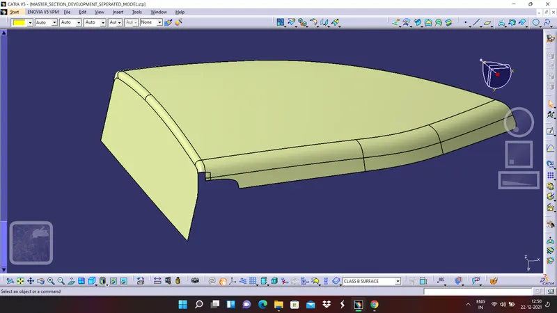
If we can observe the offset has creted some patches like surface so we have to repair it by extracting boundary and by using multi section surface command.
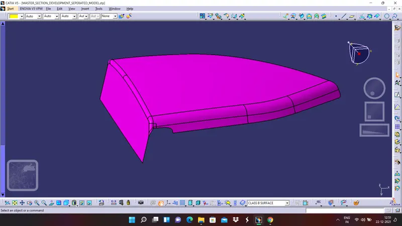
CREATION OF C SURFACE :
The class C surface is created by sweeping the class A surface with proper direction and angle. Divide the portion of class A into small small boundaries if you want. Finally make sure the C surface is joined properly.
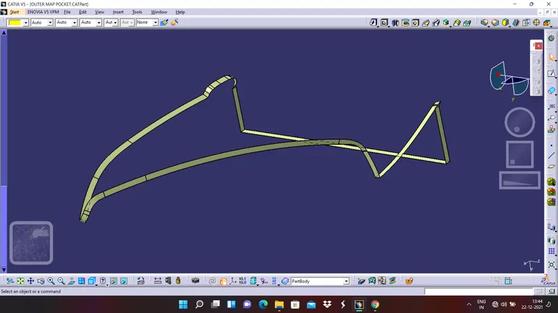
Now join it with class A surface
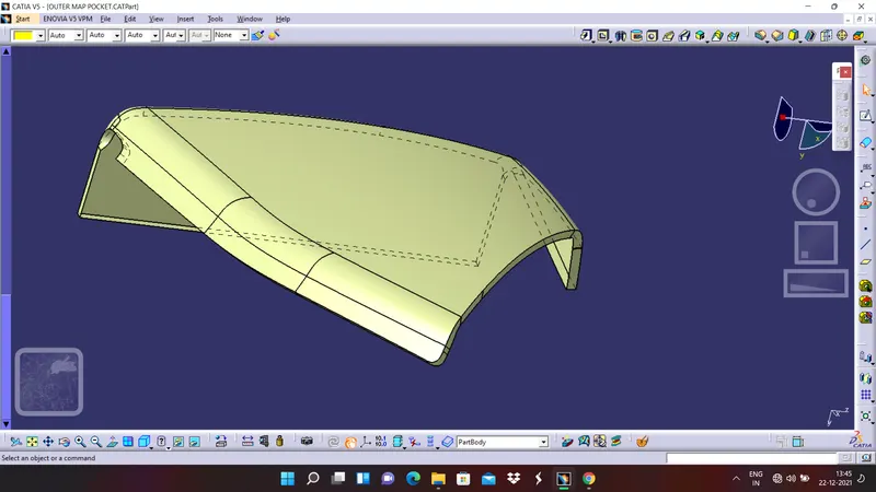
Finally trim it with class B surface and final surface of the outer map pocket has been created
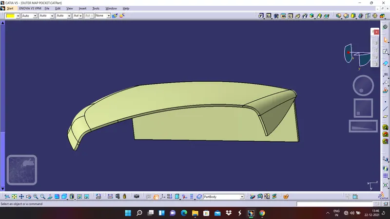
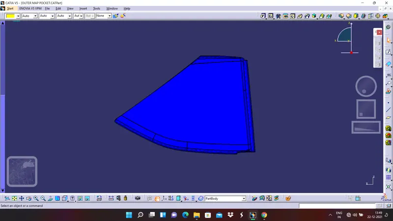
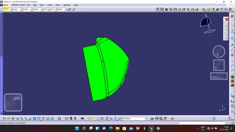
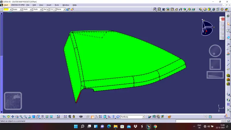
Now we have to create a solid body out of the final surface what we have, for that use close surface command and create a solid body, the views of final part body of outer map pocket are shown below,
ISOMETRIC VIEW
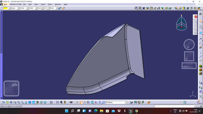
FRONT VIEW
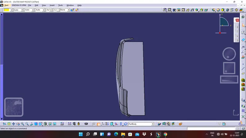
SIDE VIEW
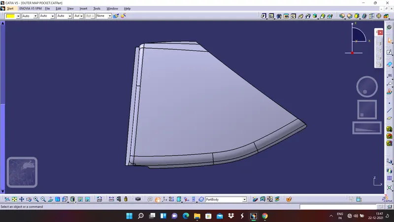
TOP VIEW
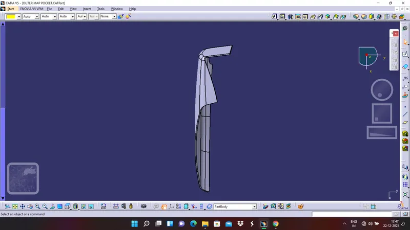
DRAFT ANALYSIS ON OUTER MAP POCKET
By using the same tooling axis which we have created for the class A surface perform draft analysis, let us see some of the images of the draft analysis,
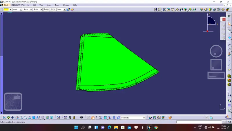
3. DESIGN OF INNER MAP POCKET:
Let us see the inner map pocket class A surface
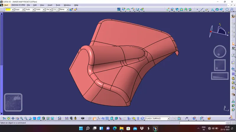
We will now create a tooling axis for the class A surface and try to perform draft analysis on it. For creating tooling axis we have to create point on the surface and by using line command try to create a line and name it as tooling axis.
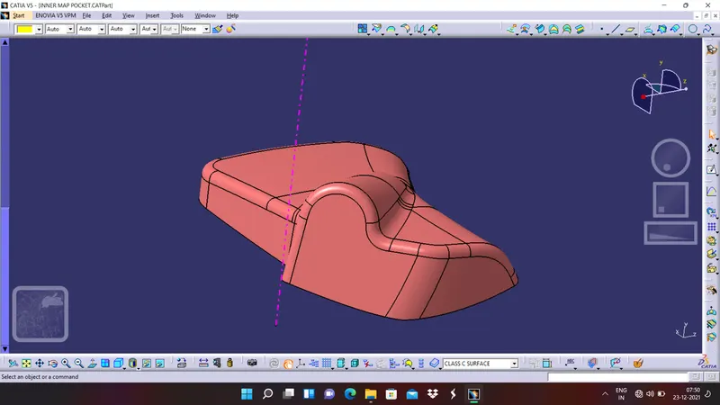
Now let us perform draft analysis and see how the class A surface is styled
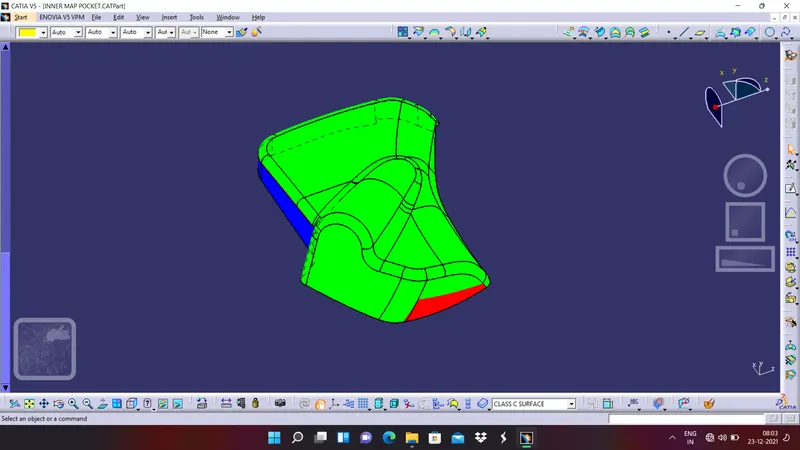
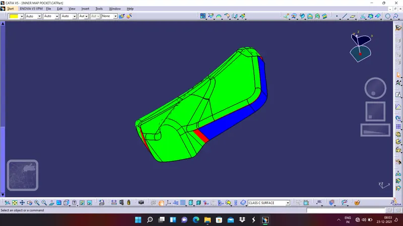
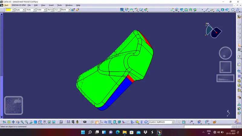
CASE STUDY 1: We can observe that the class A surface is showing negative draft, but we do not have any access to modify them so we have to ask our styling collegues to modify the design of class A surface.
CREATION OF CLASS B SURFACE:
The class B surface for the inner map pocket has been created by simply offsetting it to the required distance and in required direction.
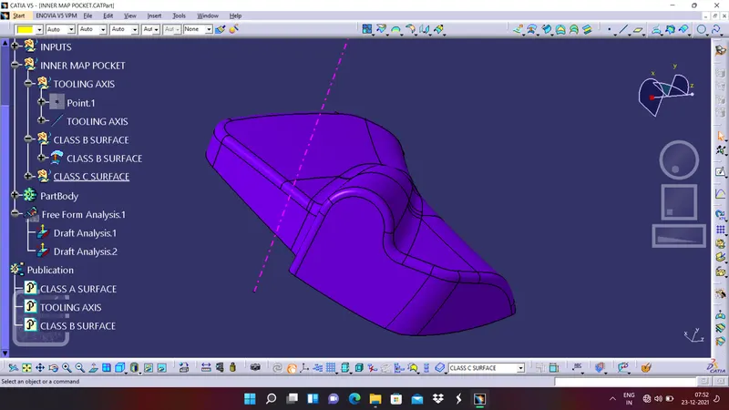
CREATION OF CLASS C SURFACE:
Similar to the previous parts here also class C surface is created by sweeping the class A surface to the required distance and in required direction and make the sweep to a single surface, use trim and join command if required.
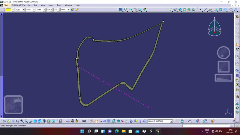
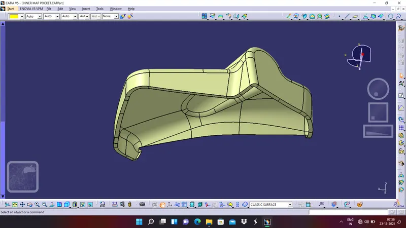
Now join class C surface and class A surface together,
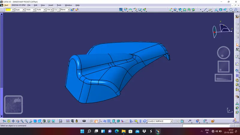
Finally trim it with class B surface and it the final surface which we have required,
By using close surface command convert the closed surface into a solid body and let us the views of the final solid body,
ISOMETRIC VIEW
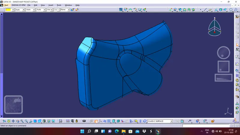
FRONT VIEW
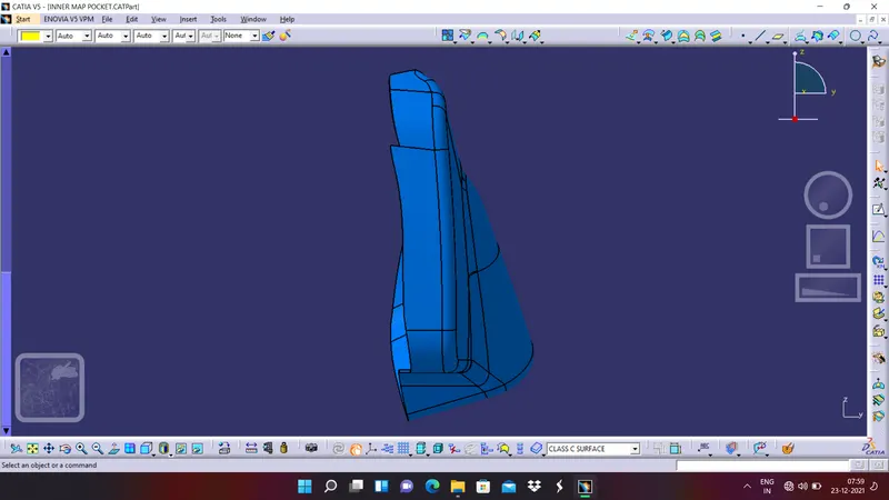
SIDE VIEW
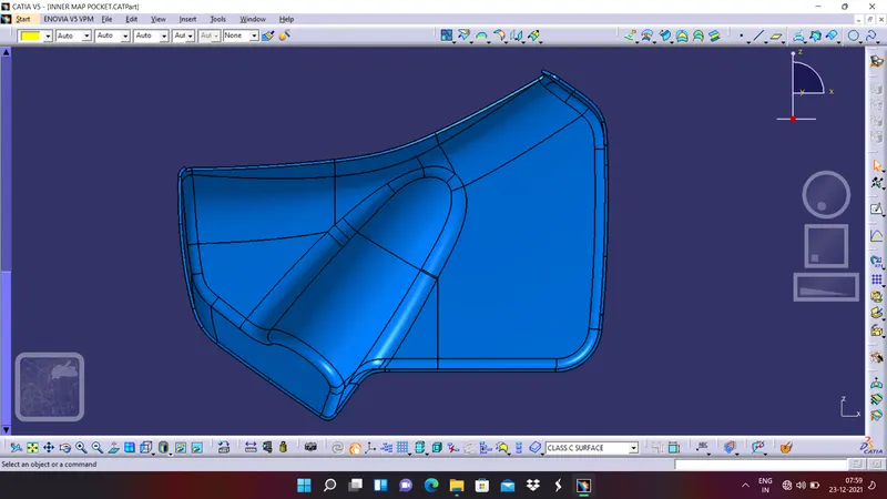
TOP VIEW
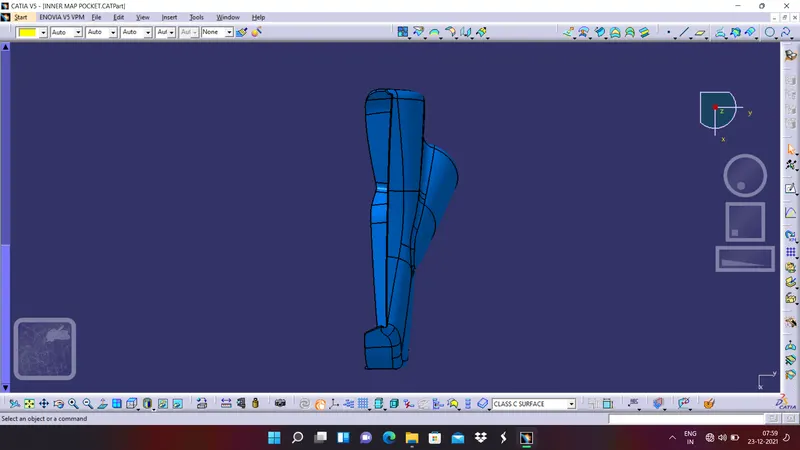
DRAFT ANALYSIS ON INNER MAP POCKET:
Let us see the images of draft analysis on the solid body of inner map pocket,
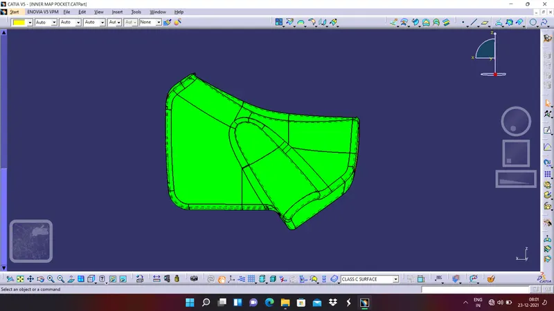
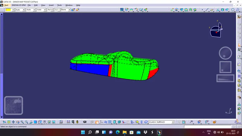
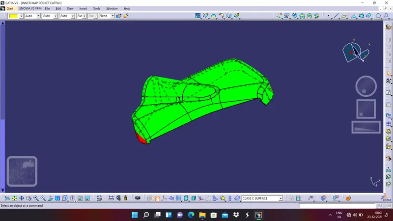
CASE STUDY 2: Like the CLASS A surface here also we can see that some faces are not clearing draft analysis and it is due to the improper class A surface and we have to inform our styling team to modify the class A surface.
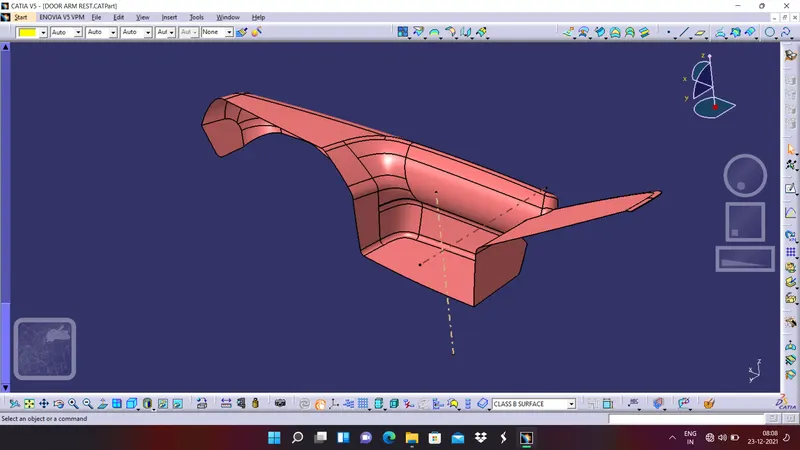
4. DESIGN OF DOOR ARM REST
First we will see the given class A surface,
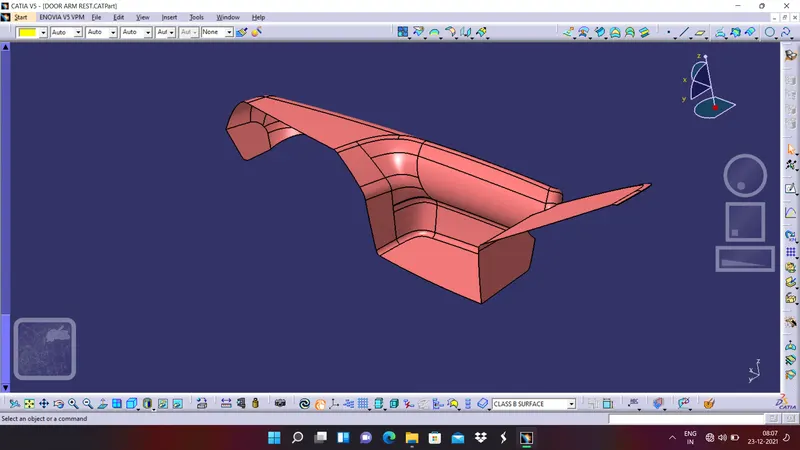
Just by seeing the class A surface we can say that the surface cannot be cleared easily by using single tooling axis and we have required to create a side core axis to avoid this problem.
- First create a point on the bottom surface and by using line command create a line in respective direction and name it as a main tooling axis.
- Similarly create a point on the side surface and by using line command create a line in respective direction and name it as side toolin axis.
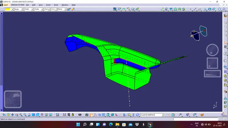
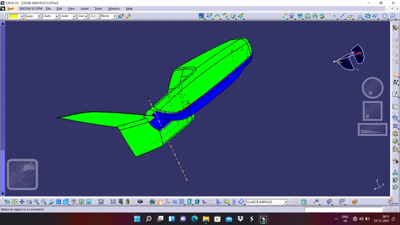
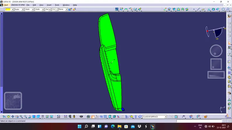
Now let us perform draft analysis on the class A surface by using the two tooling axes and observe the colour codes
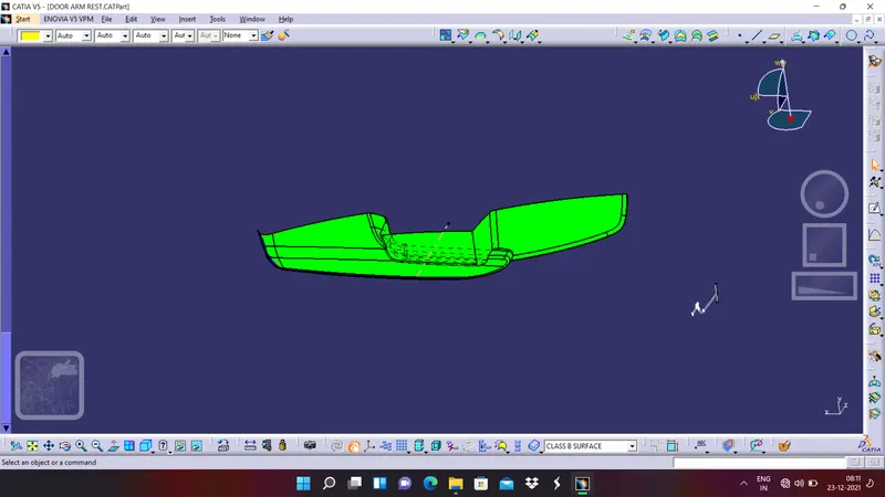
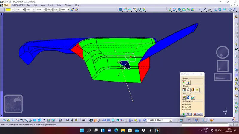
The next step in this design is to create a class B surface of the door arm rest, this can be done by offsetting the class A surface and by repairing the patches that are formed while offsetting the class A surface.
- first offset the class A surface
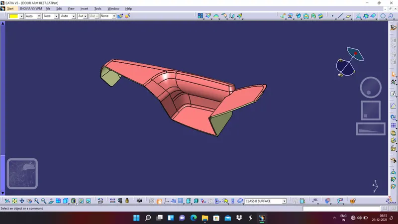
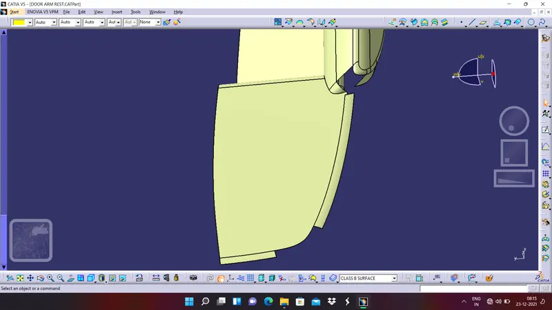
If we observe it has created patches at two stages, so we have to repair them by using multi section surface command, fill or any other suitable commands and name the repaired surface as class B surface and publish it,
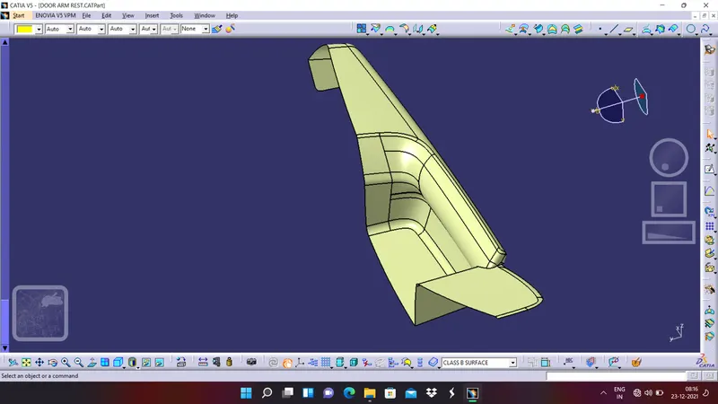
CLASS C surface of the door arm rest has been created by sweeping the class A surface to the required distance and in required direction and make the sweep to a single surface, use trim and join command if required.
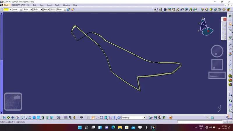
Join class A surface and class C surface and make sure there is no gap between the two surfaces.
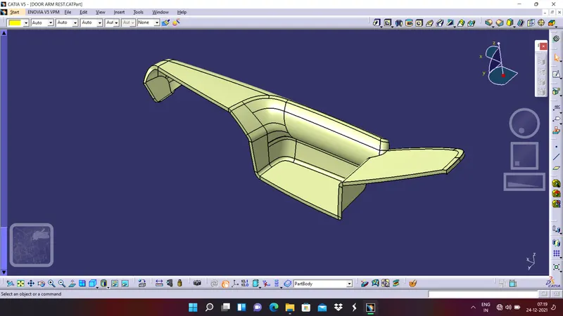
finally trim it with class B surface and the final surface has been formed
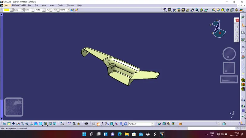
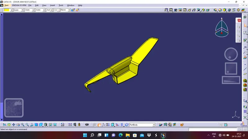
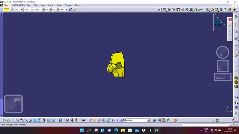
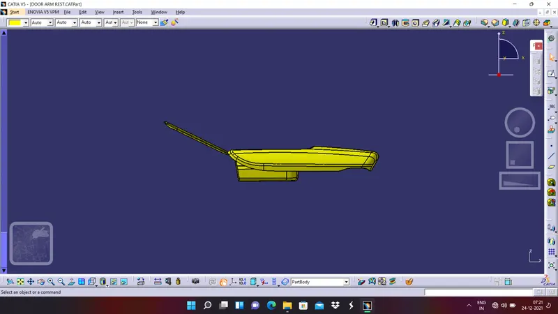
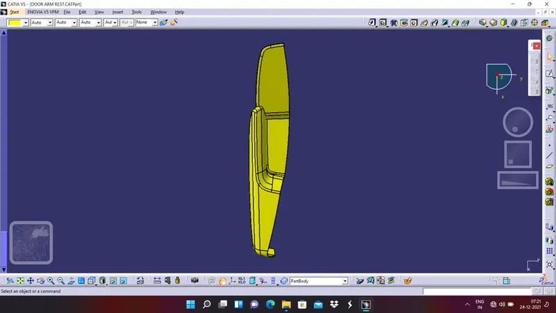
By using close surface command convert the closed surface into a solid body and let us the views of the final solid body,
ISOMETRIC VIEW
FRONT VIEW
SIDE VIEW
TOP VIEW
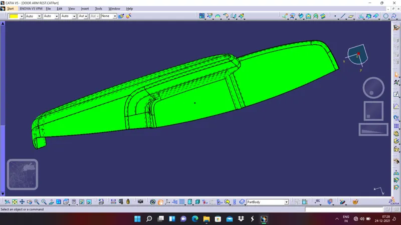
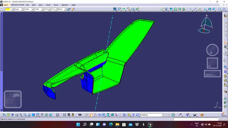
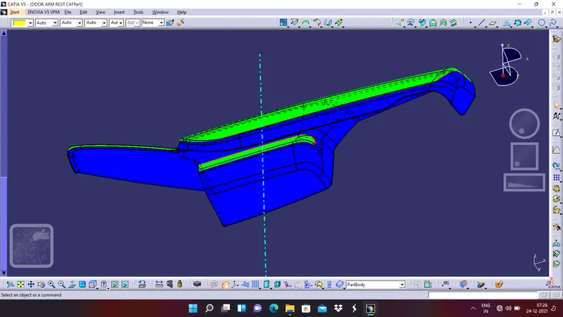
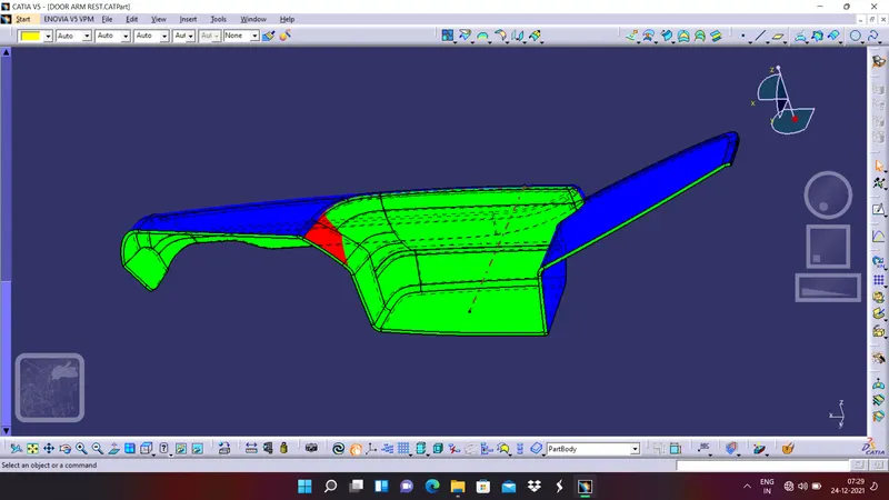
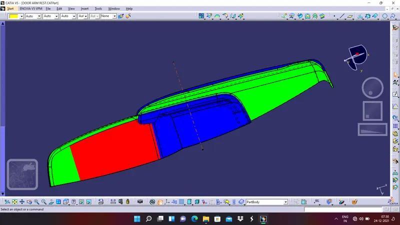
Finally perform draft analysis on the solid component and observe the colour codes what it is showing, here also draft analysis is performed by using both the axes.
ASSEMBLY OF FOUR PART BODIES:
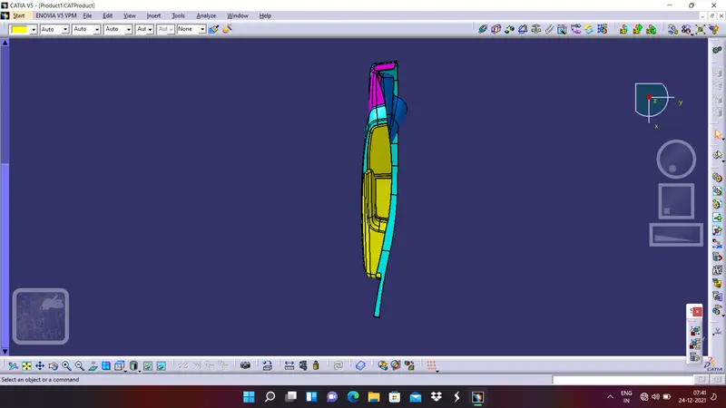
Now we have to assemble the four parts that we have created and we have to apply proper constraints to them, let us see the assembly in different views,
ISOMETRIC VIEW
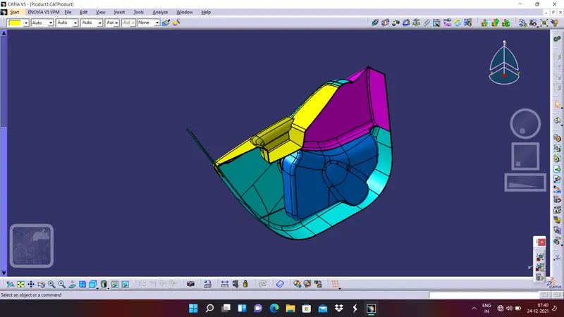
FRONT VIEW
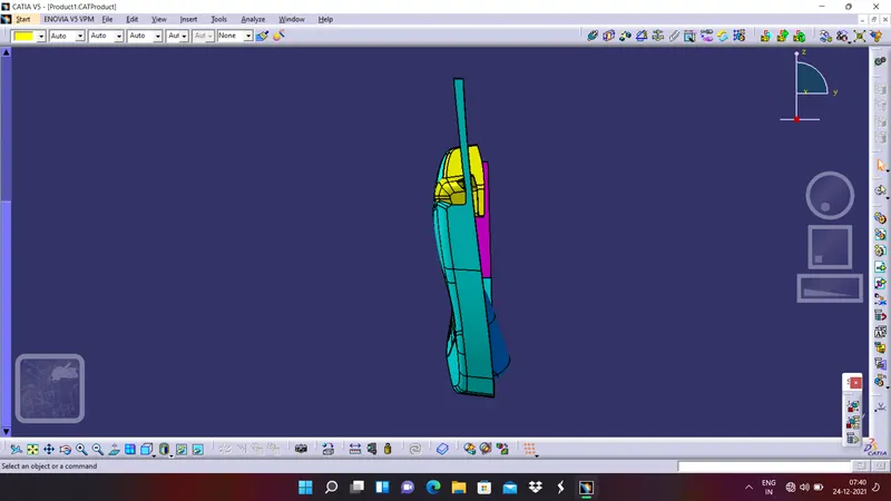
SIDE VIEW
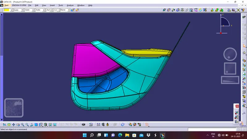
TOP VIEW
DESIGN OF B SIDE FEATURES
1. First create flanges where ever required on the part bodies. The purpose of flanges is to accomodate heatstakes on the part bodies
2. After creating the flanges create heat stakes at the places where flanges are present. For the thickness and diameter of the heat stakes refer to the master section which is given in the challenge.
3. Then create a clearance hole on the flanges which we have created previously. The clearance between flange and heat stake must be 0.1 milli meter.
4. After creating the heat stakes create ribs on the lower sub strate. The main purpose of creating ribs is to support the flange as well as ribs under the application of large pressure and force when the process of melting heat stakes is happening.
5. Then after creating the ribs now the next step is to create the dog houses. Create one dog house and translate it to places whereever required.
6. Finally attach the push pin to the dog house by using proper assembly constraints.
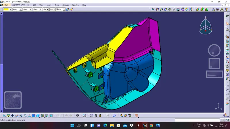
The views of the final assembly of door trim are as given below
ISOMETRIC VIEW
FRONT VIEW
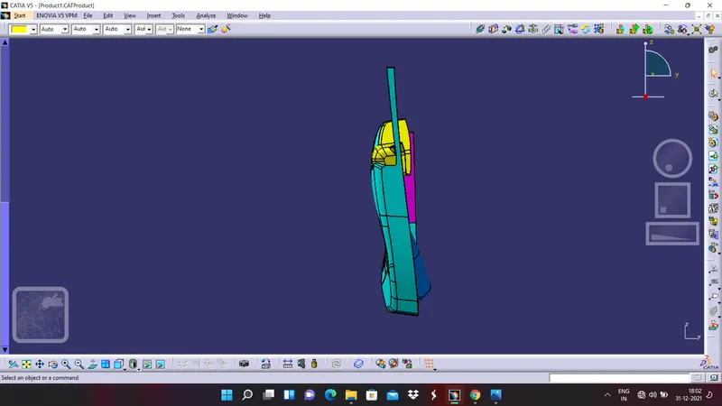
LEFT SIDE VIEW
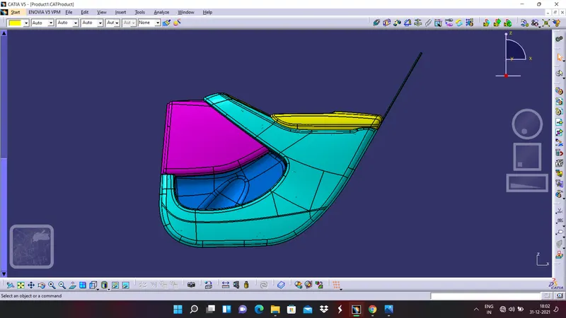
RIGHT SIDE VIEW
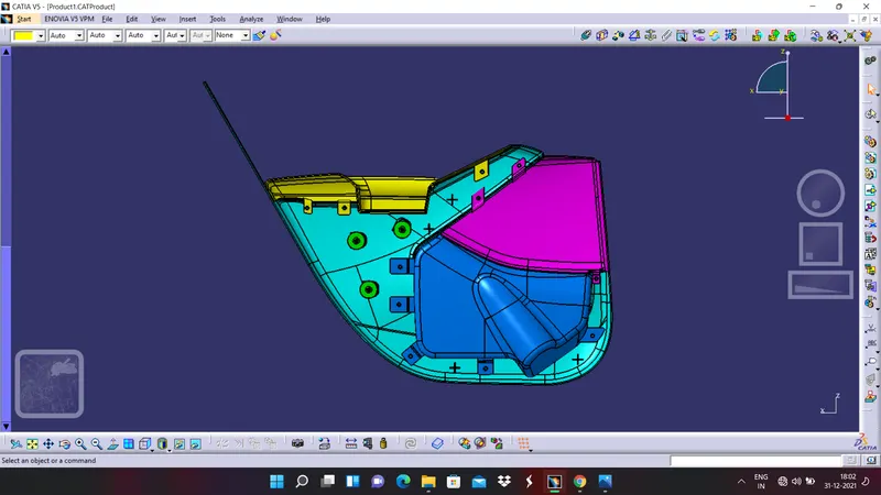
TOP VIEW
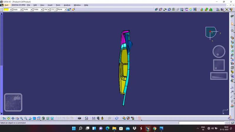
CONCLUSSION
- CLASS B and CLASS C surfaces are created to the given CLASS A surfaces.
- The design of B side features is done and they are assembled successfully.
- A detailed report has been prepared and all the part bodies and assembly has been attached to the challenge successfully.