Week 11 - Final project
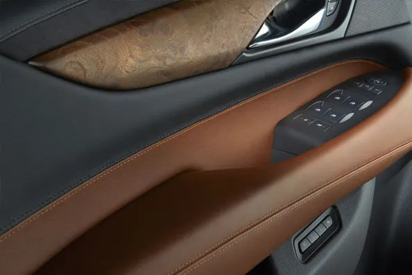
Development of Door Trim Panel
Aim :
To develop the Cad Model of Door trim panel by considering the given inputs Class A Surface by following the design rules followed by OEM Standards.
Abstract
The project deals with the procedure of designing and developing the plastic component and the engineering features act to manufacture in the injection molding process.
Plastics In Automotive Industry :
Plastics are a very appealing material for automobiles because their use leads to greater fuel efficiency: It has been determined that every 10 percent drop in vehicle weight equals a 5 percent to 7 percent decrease in fuel usage. Polypropylene more than 70% of the plastic used in automobiles comes from four polymers: polypropylene, polyurethane, polyamides, and PVC.
Methodology :
Class A Surface was developed by the Styling team and then the development team check the feasibility of the Class A Surface which they received.
After they check then they work to Develop the B surface of the part
Then the C surface is developed and the body is closed.
After completing and thickening the part, the B Side (attachment) features are developed.
CLASS A SURFACE :
The class a surface is an initial process to bring the plastic component design from scratch to mass production. The class a surface it has no thickness. The Class A surface is used for the aesthetic surface of a product. From Class A surface the solid model is created.
- TOOLING AXIS :
The tooling axis is a direction to open the mold open or close or the cavity and the core to open and close. The tooling axis is used to create the draft analysis. Most of the designers will choose the hole in the surface or the flat surface to choose as a tooling axis point. The choosing plane in the tooling axis point main criteria is to clear all the faces on the surface. The tooling axis is to create because the parallel faces in the surface make trouble in the drafting to avoid the intersecting lines.
Class B Surface :
The B surface is created by thickening the A surface. The A surface has no thickness. The B Surface is for Engineering purposes. To thicken the A surface.
Class C Surface :
A surface means a visible surface.it will give styler. B surface means the thickness of a part it is not visible it is inside part. c surface means A and B combined to give C surface. Class C surfaces are the backside surfaces that can have tool marks, flashes, and other imperfections without hurting appearance, function.
Draft Analysis:
Drafting analysis is used to make the product in taper or minimum angle to avoid the damage of the product. when the product is on a flat surface it may make wear and tear and to avoid friction shrink and use for the ease ejection.
Door Trim Parts
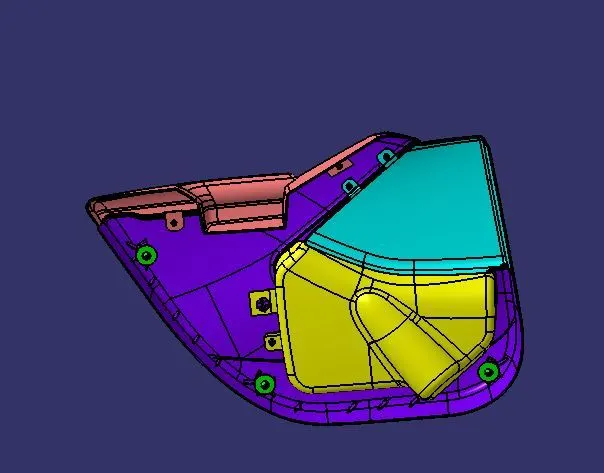
The 4 number of parts are deal with the project
- Arm Rest
- Lower Substrate
- Bottle Holder
- Map Pocket
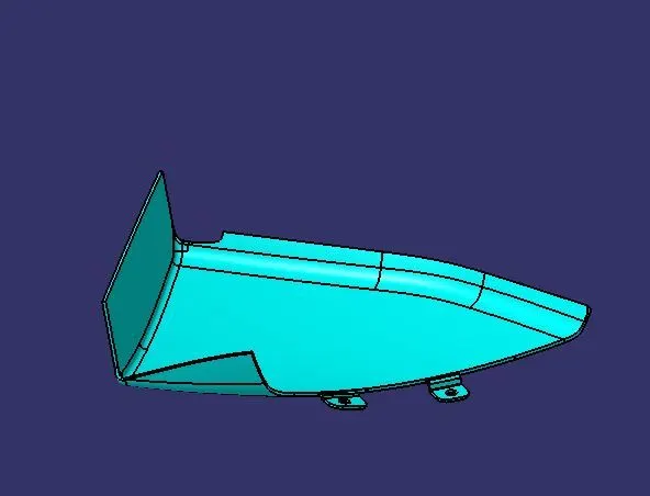
MAP POCKET :
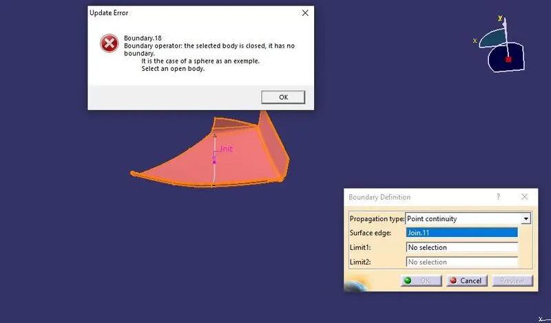
- The First step is to join the Class A surface by using the joining command. By joining the class A Surface and using the boundary command, inspect the quality of Class A.
- After Inspecting the surface quality the tooling axis which to create.
- For the map pocket, the tooling direction - Y Which is clearing the direction. It clears most of the areas.
- Then the draft analysis tool is used to check the Class A Surface.
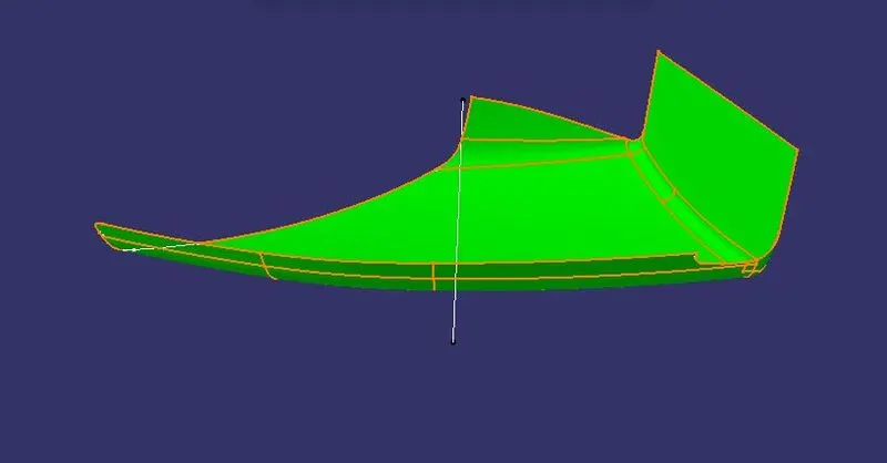
Map Pocket Draft Analysis
In the above pic the all the areas have been clearing the tooling axis.
Class B Surface :
The Class B Surface is offset 2.5 mm from the A surface according to the given input in the Master Section.
By Doing the offset method most of the B surface is not fully achieved due to the fillet corners.
The patches do not form the tangency boundary. The issues are to be fixed . Then the to proceed further step is proceed.
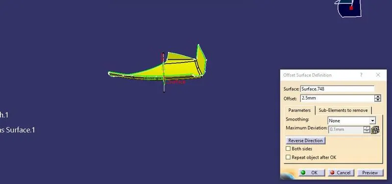
Class B Surface
Class C Surface:
Extract The boundaries of Class A
By using the sweep command with respect to a draft direction the sweep command is to give by min of 3 deg in the outwards to clear the draft analysis.
Join All the sweep commands and form the Class C Surface.
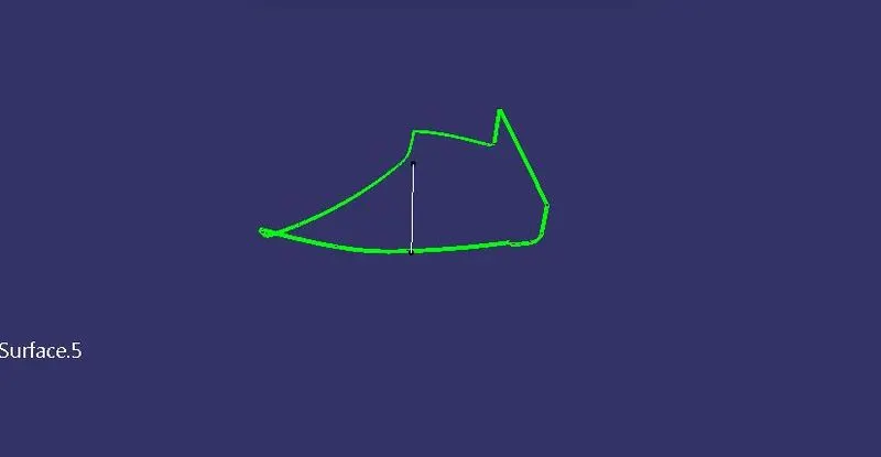
C Surface
Then Join the A Surface and trim with the B Surface.
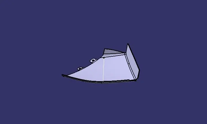
The closed Surface of the map pocket.
Bottle Holder :
CLASS A Surface :
Join the given Class-A Surface by using the join and inspecting the boundary of Class A.
Then the tooling direction has to be given to clear the draft Analysis.
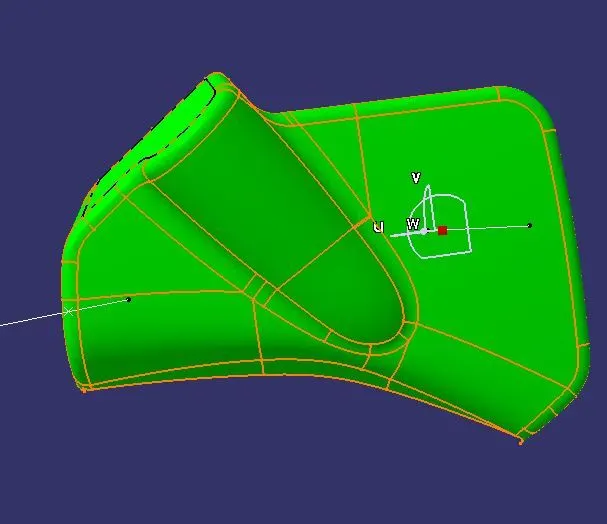
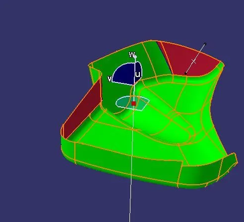
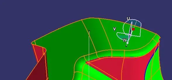
On the above surface, the side coring ais is used to clear the draft analysis.
Class B Surface :
The Class B Surface is offset 2.5 mm from the A surface according to the given input in the Master Section.
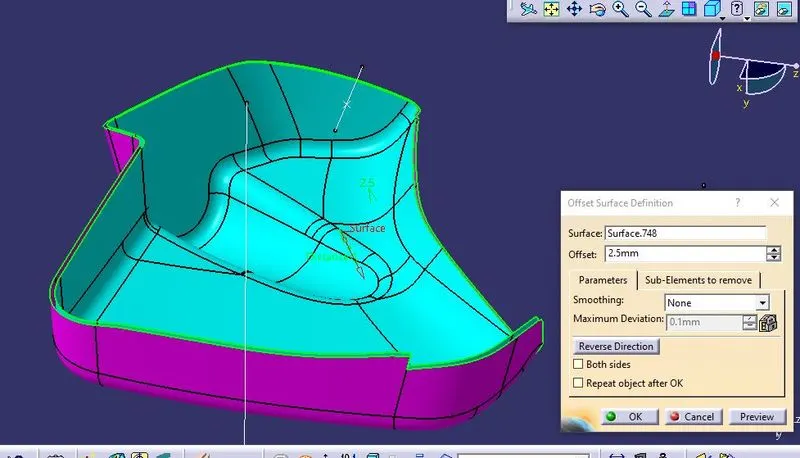
Class C Surface :
After creating the A and the B Surface The c surface is created by extracting the A surface boundary and by sweeping along with the draft direction of the tooling axis.
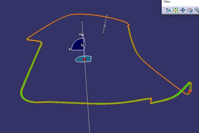
Draft Analysis of C surface
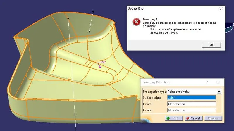
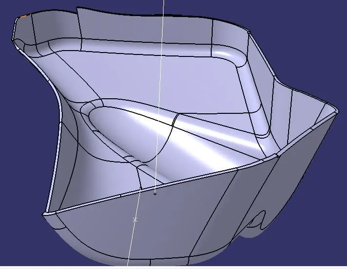
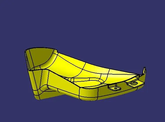
Bottle holder Closed Surface
LOWER SUBSTRATE :
Class A Surface :
The Class A surface of the lower substrate is extended by a small portion of the surface by using a split command to correct the patch
After correcting it check the boundary of the Class A Surface.
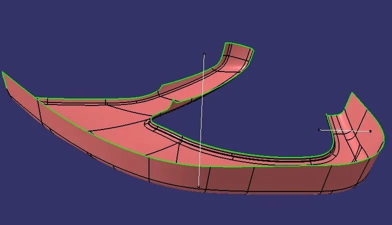
Tooling Axis
- After Inspecting the surface quality the tooling axis which to create.
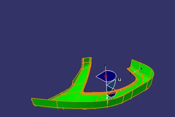
- For the Lower Substrate the tooling direction - Y Which is clearing the direction. It clears most of the areas.
- Then the draft analysis tool is used to check the Class A Surface.
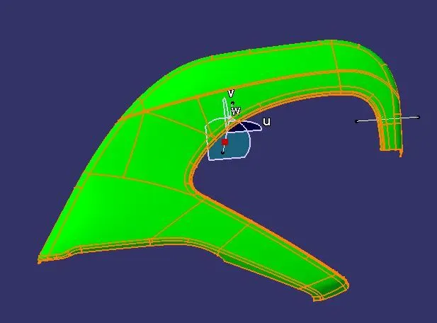
Class B Surface :
Once the draft analysis is inspected the BSurafce is to be developed by using the offset method.
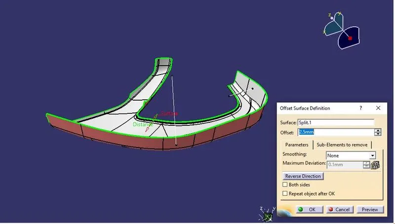
CLASS C SURFACE:
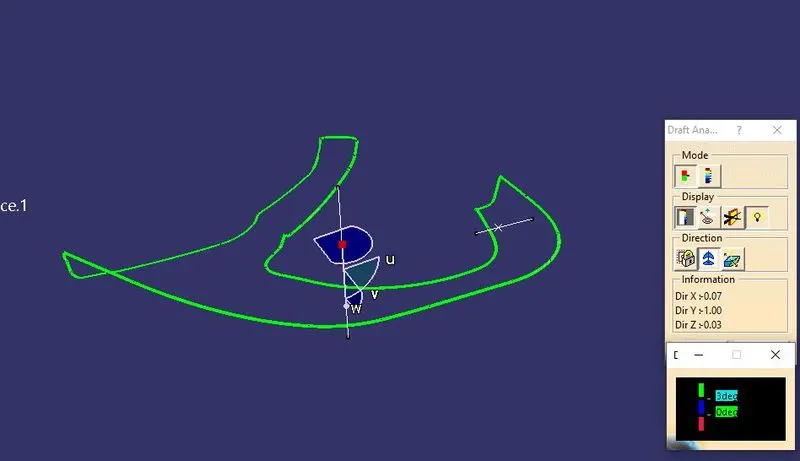
The above pic shows the C Surface along with the draft analysis.
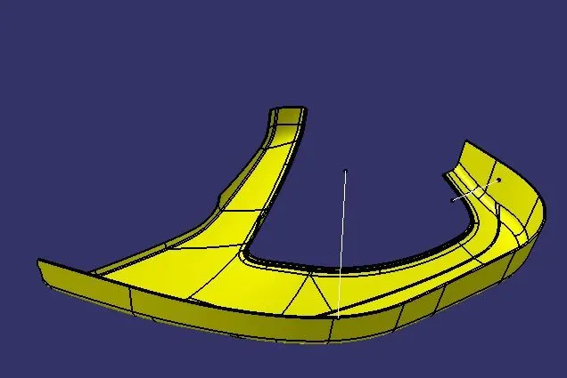
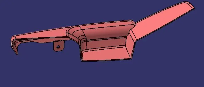
Arm Rest :
Join the given Class-A Surface by using the join and inspecting the boundary of Class A.
By checking the armrest class A Surface it shows some extension boundaries. The issue has to be fixed.
After inspecting the Class A Surface then visually check for the axis to clear.
Then the tooling direction has to be given to clear the draft Analysis.
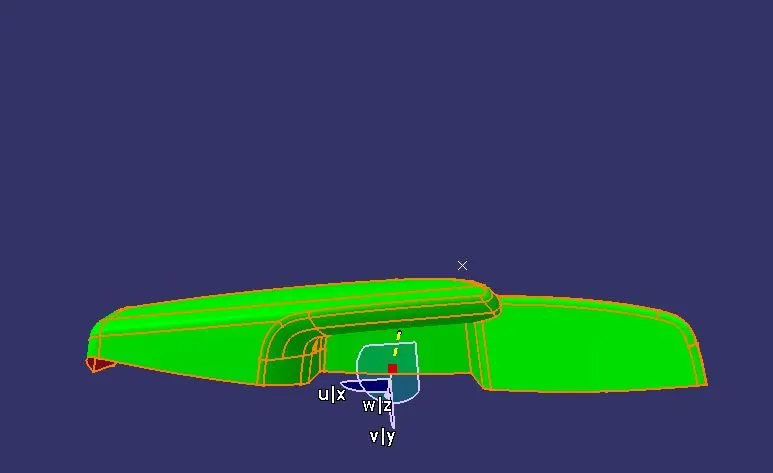
The above diagram is the tooling axis in the X Direction. By viewing in this direction the tooling axis is not clearing the entire process. Most of the portions are not clear the min draft is 3 deg.
After checking the main tooling axis than with the help of the side coring axis, the portion is checked
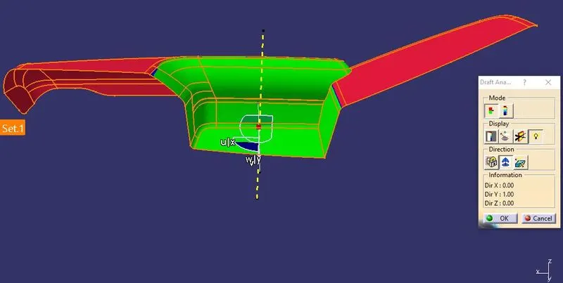
The above pic shows the side coring tool axis
By viewing the side core tooling axis and the main tooling axis the Class A Surface is not clearing the draft analysis. In this case, the styling team of A surface has to rework the surface which is the report given by the development team.
Class B Surface :
After the rework is done by the styling team the B Surface which has to develop.
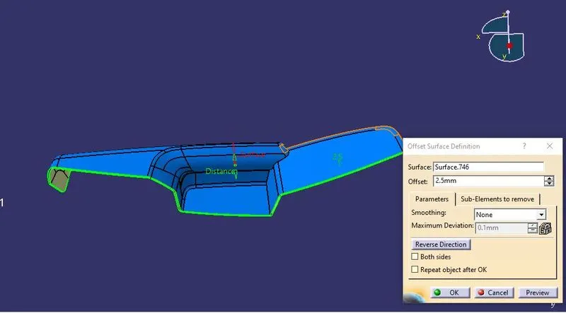
Class C Surface :
By Extract, the A surface boundary the C surface has been created by using the sweep command.
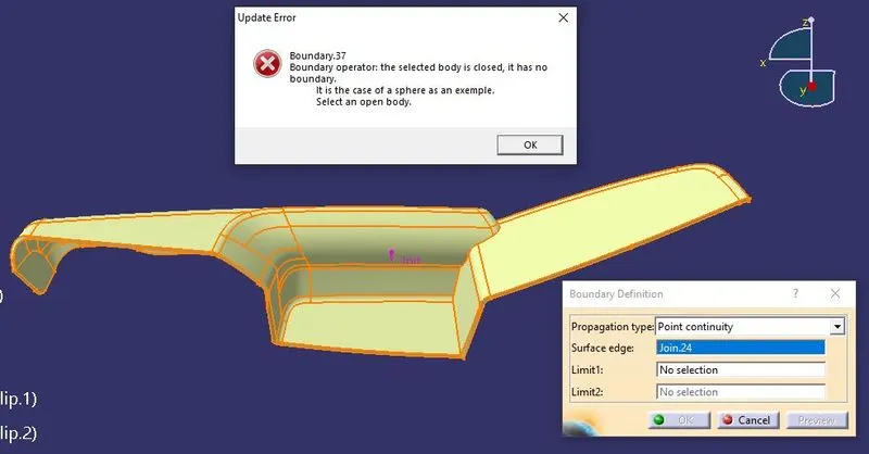
As mentioned earlier the armrest is not clearing the draft analysis. so the above part is not preferable to manufacture.
B SIDE FEATURES
- Screw Boss
- Dog House
- Ribs
Screw boss is a secondary feature that is the creation in the engineering feature. Increase the height of the component and position the screw boss. Boss is used to attaching and in the assembly feature.
Rules for screw boss
Wall thickness = 0.6* Thickness of component
Fillet radius = 0.25 mm
Draft angle =0.5 deg.
Heat stakes :
Heat stakes are to join the two dissimilar points in the plastic. Heat Staking is a pulsed-heat process to join two or more parts out of which one at least is made of plastic. The process is to deform the plastic material using heat and force at a set process time. The bond is made by partially de-forming the plastic part in order to fix the other.
Procedure For Heat Stakes :
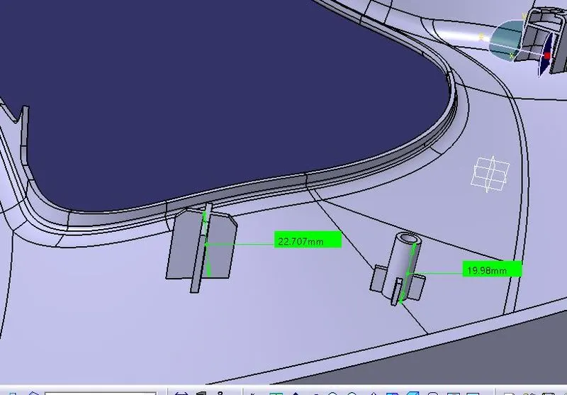
The Heat stakes height should be the height of 16-20 mm above the lower substrate.
The dia of the heat stakes should follow the guidelines of 6-8 mm.
To support the heat stakes the ribs should get attached with the heat stakes.
The height of the ribs should be 6-8 mm above the surface of the lower substrate.
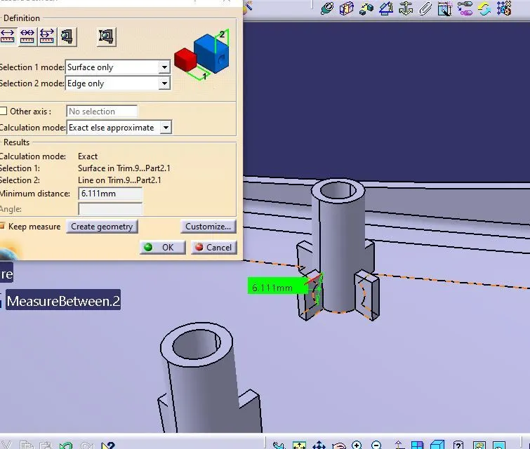
Height of Rib
After creating the rib the flange had to create. The flange which is placed above the rib is attached to the screw boss.
In the plastic welding process, the screw boss gets to join the two parts.
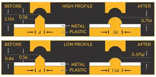
The Flange thickness it has the same as the thickness of the closed surface of the door panel.
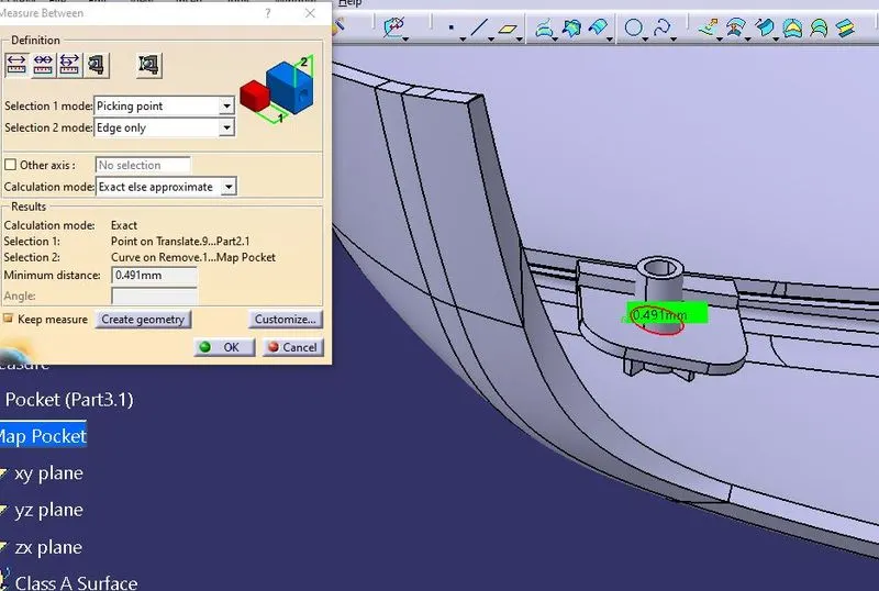
The Flange clearance for the heat stakes should be 0.5mm.
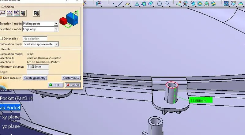
The height of the heat stake after the flange should be 10-12mm.
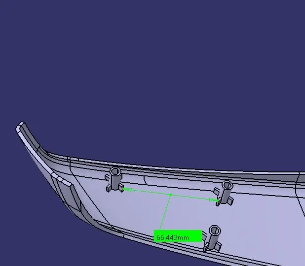
The length of the heat stakes should be 60.-80 mm between the heat stakes.
4 WAY LOCATORS :
A 4-way pin restricts 4 degrees of freedom along 2 axes. A round locating pin located concentrically in a hole is a common application of a 4-way pin and helps to further secure the piece.
The dog house is created to avoid the sink mark and increase height.
When the screw boss is perpendicular to the tooling axis it is difficult to clear the drafting analysis. so the dog house is created to clear the tooling axis.
The height of the 4-way locator should be higher than the heat stakes.
DOG HOUSE :
The dog house is created to avoid the sink mark and increase height.
When the screw boss is perpendicular to the tooling axis it is difficult to clear the drafting analysis. so the dog house is created to clear the tooling axis.
PROCEDURE :
The doghouse height is to be 28 -30 mm for the door trim panel.
The coring height is to be 3-6 mm.
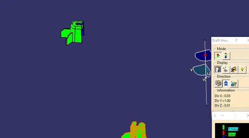
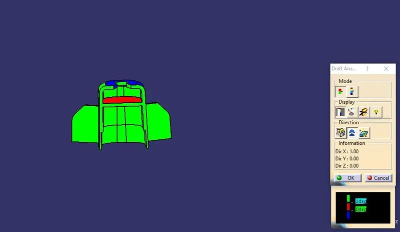
The Draft for outside the dog house is 1.5 deg and for the inside the doghouse, the inside 4 all is 0.5 deg.
The min fillet is to be given to avoid sharp edges.
The thicknesses of the dog house are 2mm.
Draft Analysis of dog House
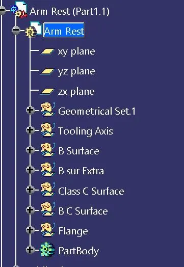
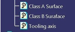
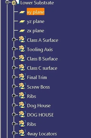
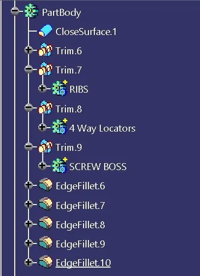
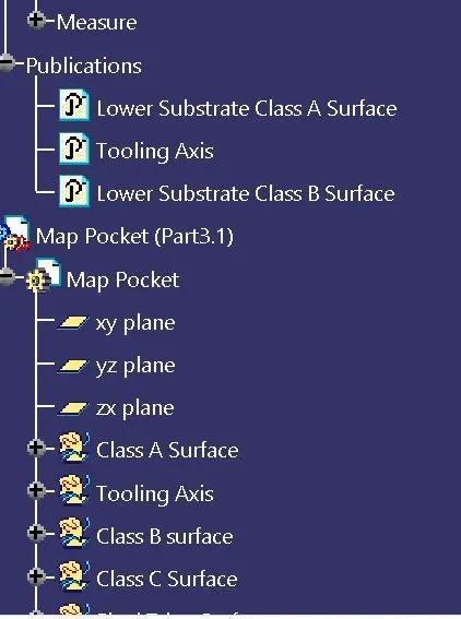
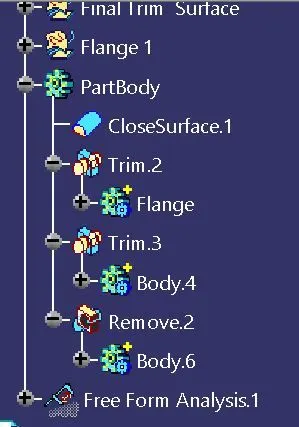
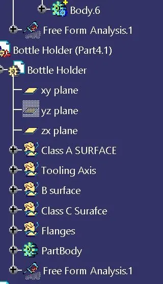
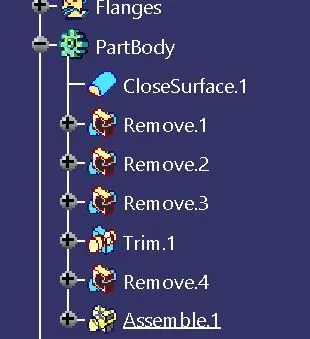
Tree Structure :
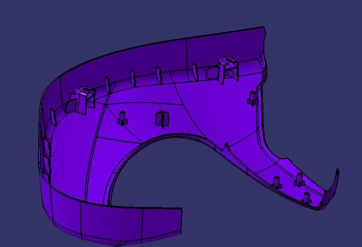
Result :
Note: Finally it has been concluded the door trim panel project has made us explode a lot of surface commands and achieve the project work in the OEM standards.