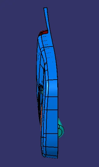
Week 11 - Final project
DESIGN AND DEVELOPEMENT OF A DOOR TRIM PANEL:
OBJECTIVE:
The objectives of this assignment are:
- Create Tooling axis for each and every component provided.
- Create the Class B and Class C surfaces from the Class A surface as provided.
- Create different attachment features by following the master section provided.
- Create Joining flanges, Heat stakes, Locator pins, Ribs, and Push pins with Dog house by following the design rules.
- Create Parting lines.
- Perform Draft Analysis on all the required surfaces and the final component.
- Create the Assembly of all the components.
INTRODUCTION:
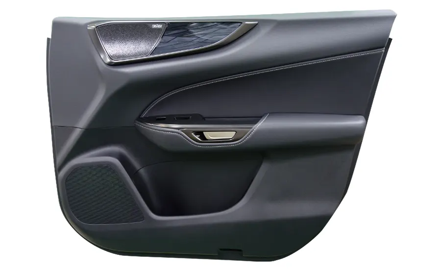
- Door trim is the interior part of the car doors which provides good aesthetics and improves the look of the car.
- Next to the dashboard, the door trims are the interior parts that contain the most controls and decorative parts. As such, there is a necessity for balancing gap between parts, as well as an overall sense of unity between the numerous parts.
- Apart from the aesthetics it also serves a lot of other important purposes such as it joins with the sheet metal part behind it.
- In order to join different plastic components with each other we need to create required attachment features as per following the design rules.
- Not only attaching with the plastic components the plastics are also joined with the sheet metal parts.
- So we have to provide features to help join the plastic with the sheet metal parts.
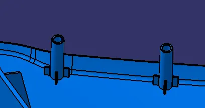
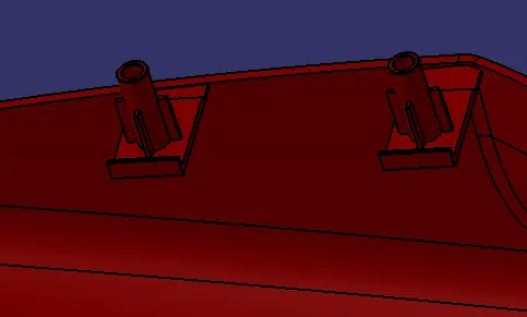
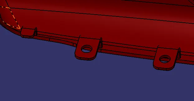
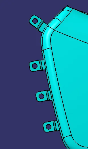
- To join the plastic components between each other we have to create joining flanges and give proper heat stakes on the other part so that the heat stakes can move into the flange with the hole provided and after heat staking process it melts and joins both the plastic components.
- The heat stakes should have ribs in order to hold the heat stakes firmly so that after heat staking process it stays firmly in its position without getting disturbed.
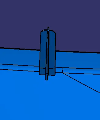
- Also in order to locate the different positions of the plastic components we need to provide locating pins at some places.
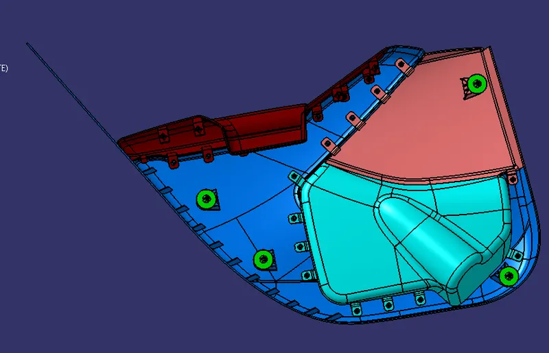
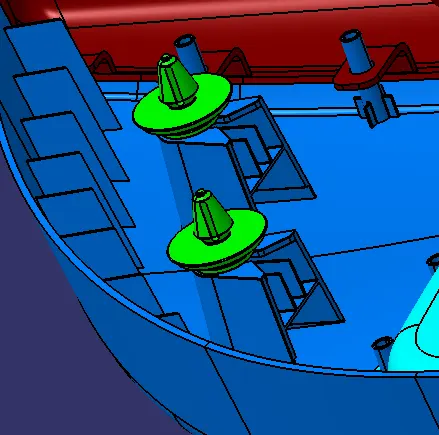
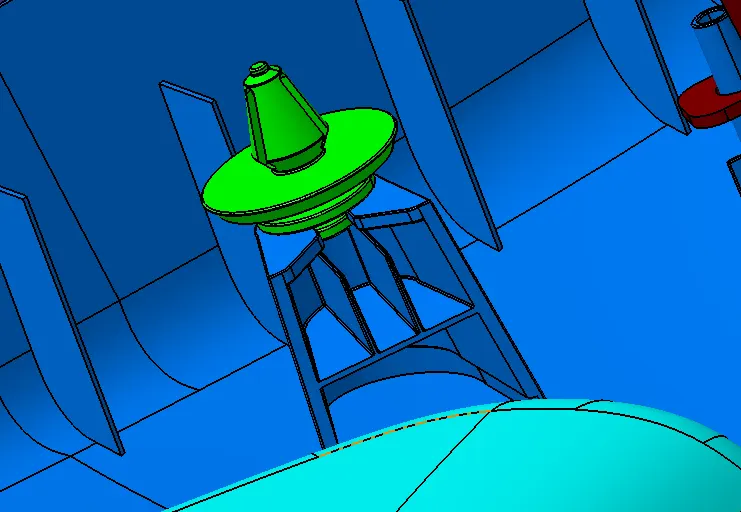
- Now in order to join the plastic components with the sheet metal parts we also need to provide push pins.
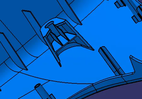
- As there is a huge gap between the sheet metal parts and the plastic components, we need a veery long push pin but having such a long push pin will not serve the purpose because as the length increases the strength of the push pins decreases and it may fail during the assembly process itself.
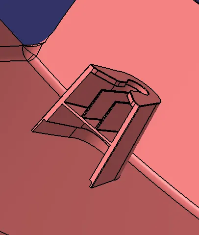
- So dog houses are made on which the push pins are located and they can be easily assembled into the sheet metal parts.
- The dog houses provide ample amount of strength to the push pins and it also reduces the length of the push pins.
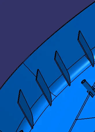
- We also need to provide ribs in necessary areas which increase the overall strength of the plastic component.
- So in this assignment we need to create all the required surfaces form a closed body and create all the attachment features and engineering features as per the design rule.
COMPONENTS TO BE DESIGNED:
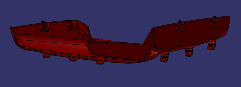
- The door trim mainly consists of 2 halves the upper half and the lower half.
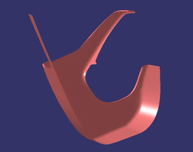
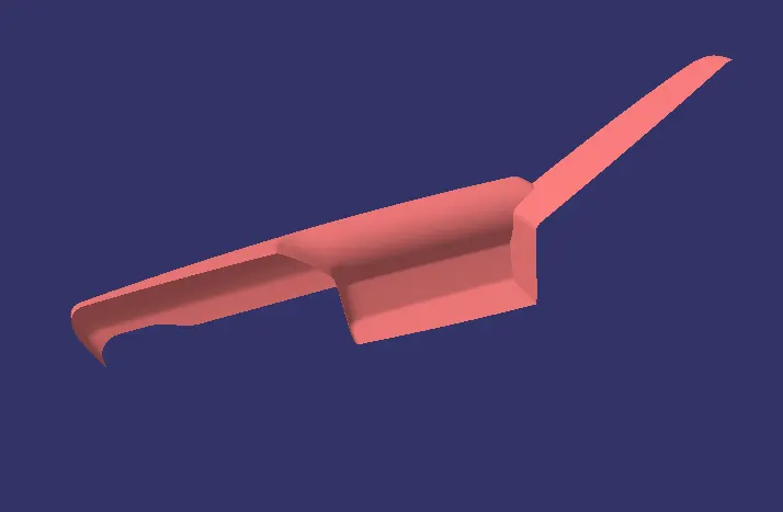
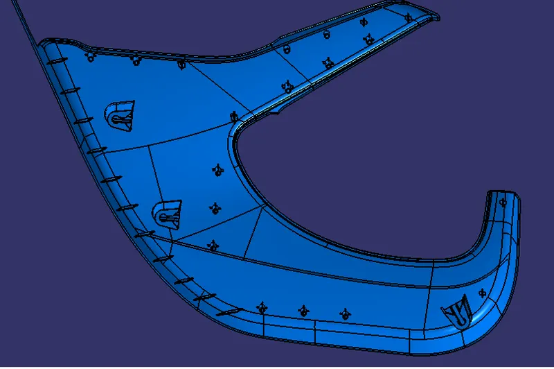
- In this assignment we are going to design the lower half of the door trim panel and it consists of four parts they are: -
- Lower Substrate
- Arm Rest
- Map Pocket
- Bottle Holder
LOWER SUBSTRATE:
ARM REST:
MAP POCKET:
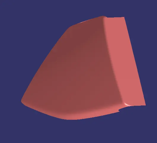
BOTTLE HOLDER:
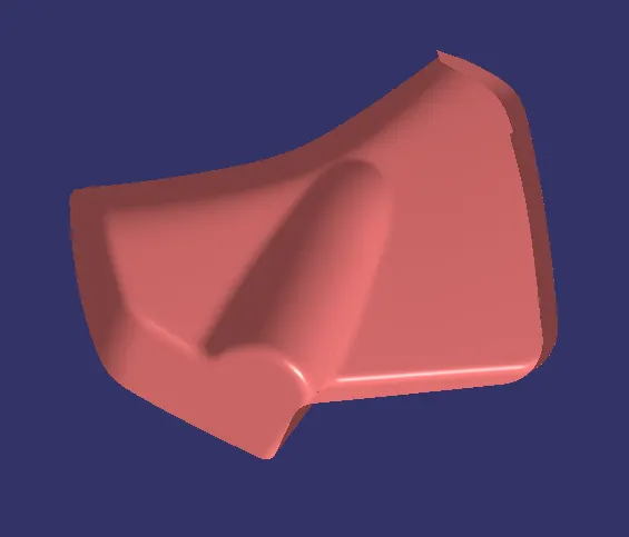
DESIGN METHODOLOGY:
STEP 1: -
- First by inspecting the class A of the component we need to decide the core and the cavity half.
- After that we need to decide the tooling direction and create the Tooling axis.
CREATION OF TOOLING AXIS:
1. LOWER SUBSTRATE:
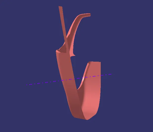
2. ARM REST:
MAIN TOOLING AXIS:
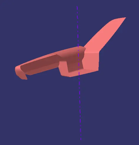
SIDE CORE TOOLING AXIS:
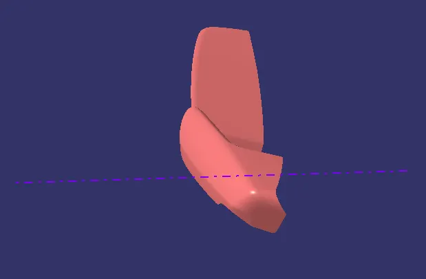
MAP POCKET:
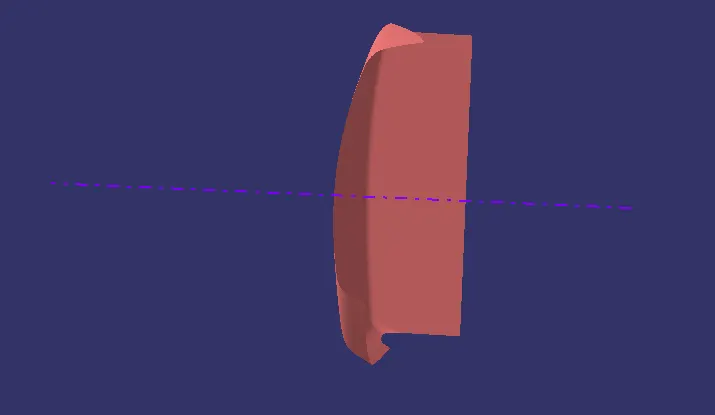
BOTTLE HOLDER:
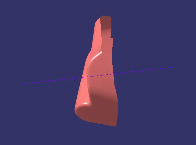
STEP 2: -
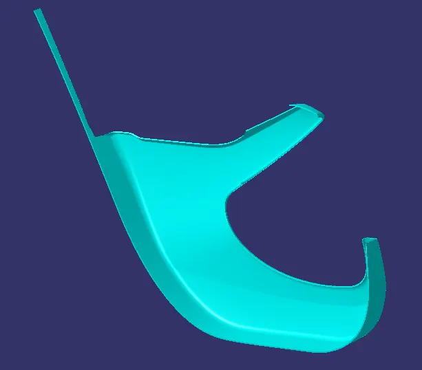
- After creation of the Tooling axis we need to create the Class B and Class C surface from the given Class A surface and form a closed body
1. LOWER SUBSTRATE:
CLASS A:
CLASS B:
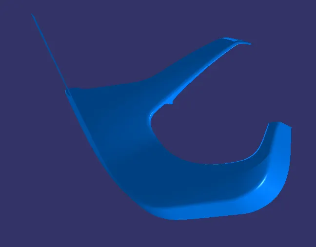
CLASS C:
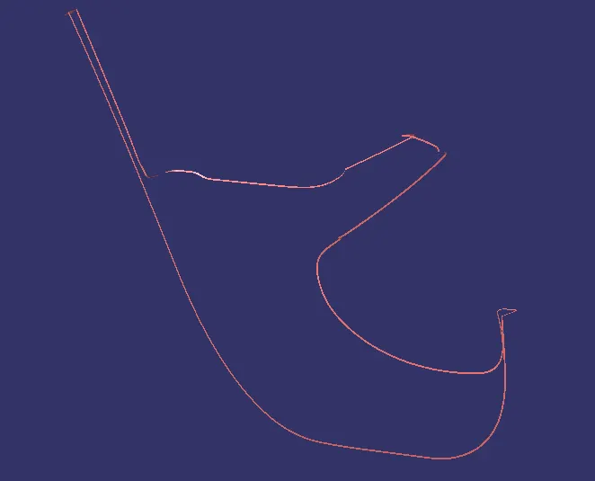
FINAL COMPONENT:
2. ARM REST:
CLASS A:
CLASS B:
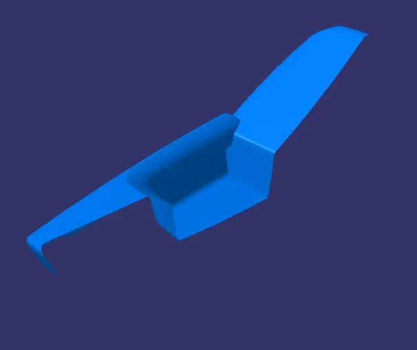
CLASS C:
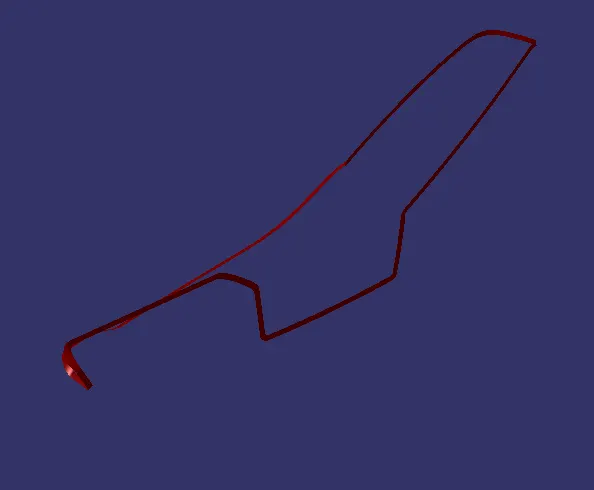
FINAL COMPONENT:
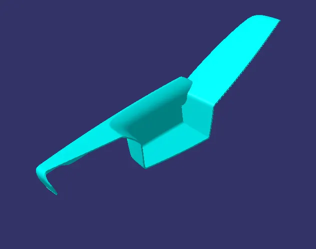
3. MAP POCKET:
CLASS A:
CLASS B:
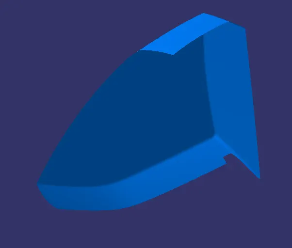
CLASS C:
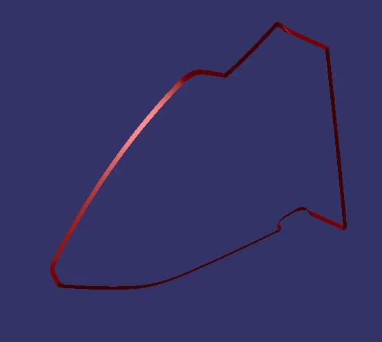
FINAL COMPONENT:
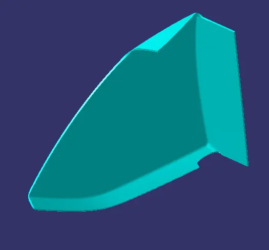
BOTTLE HOLDER:
CLASS A:
CLASS B:
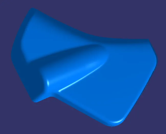
CLASS C:
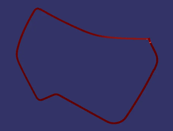
FINAL COMPONENT:
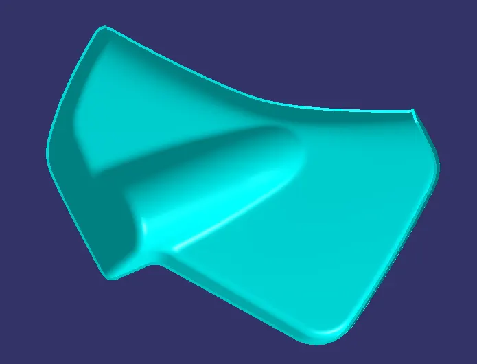
STEP 3: -
- After creation of closed body of all the components the gaps between every part must be checked in order to ensure that no part is intersecting with each other.
- The minimum gap between each and every component must be 0.5mm.
- After verifying the gap between the components we should create the joining flanges and the heat stakes as per the master section provided to us.
DESIGN RULES FOR RIB CREATION:
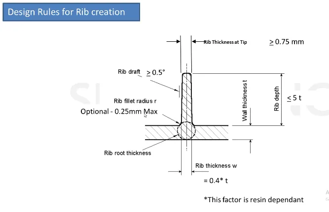
1. RIB HEIGHT: 5*T
Where T = Nominal wall thickness
Rib Height = 5*2.5 = 12.5mm
2. RIB THICKNESS: 0.4*T = 1mm
3. RIB THICKNESS AT THE TOP: > 0.75mm
4. FILLET RADIUS: 0.25mm Maximum
5. DRAFT: 0.5 deg per side and on all faces
6. RIB ROOT THICKNESS: To be carried out
7. SPACE BETWEEN RIBS:
`(Height)/(Width)=3/1 or 2/1`
DESIGN RULE FOR 4-WAY LOCATOR PIN:
The locator pins can follow the same rule for the Ribs i.e.
1. RIB HEIGHT: 5*T
Where T = Nominal wall thickness
Rib Height = 5*2.5 = 12.5mm
2. RIB THICKNESS: 0.4*T = 1mm
3. RIB THICKNESS AT THE TOP: > 0.75mm
4. FILLET RADIUS: 0.25mm Maximum
5. DRAFT: 0.5 deg per side and on all faces
DESIGN RULE FOR HEAT STAKES:
- The heat stakes should have an outer diameter of 7.5mm and inner diameter of 5mm.
- The height of the heat stakes should be 12mm from the flange so that heat staking procedure would occur properly.
- The heat stakes must have ribs attached in order to provide strength to them and hold them firmly.
NOTE:
- The hole clearance for the heat stakes must be 0.5mm.
- And the hole clearance for the locator pins must be 0.1mm.
DESIGN RULE FOR CREATION OF DOG HOUSE:
General Guidelines for Dog House:
- "C" is where the doghouse contacts the backside of the surface
-
Doghouse wall thickness at the intersection of the part wall (C) should be 40% or less than the main wall stock (T).
-
Height of (B) should be between 3.0 – 6.0 mm
CREATION OF ENGINEERING FEATURES ON THE COMPONENTS:
1. LOWER SUBSTRATE:
HEAT STAKES:
LOCATOR PINS:
DOG HOUSE:
RIBS:
2. ARM REST:
JOINING FLANGE:
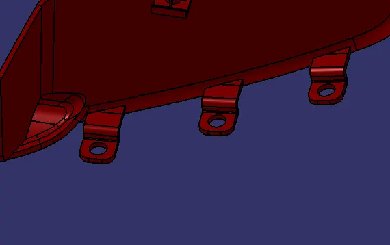
3. MAP POCKET:
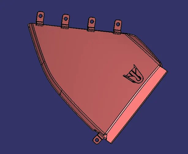
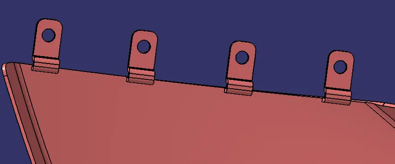
JOINING FLANGES:
DOG HOUSE:
4. BOTTLE HOLDER:
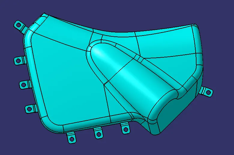
JOINING FLANGES:
STEP 4: -
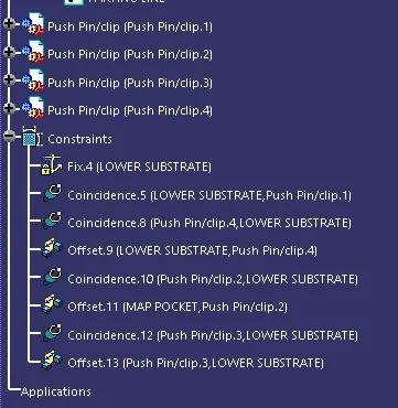
- After creating all the engineering features and the attachment features that are required to join the component we assemble the components in the Assembly Workbench and position the Push Pins above the dog houses with proper constraints.
PLACING THE PUSH PINS:
STEP 5: -
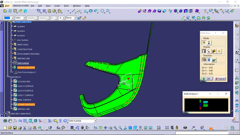
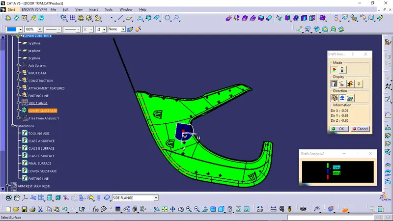
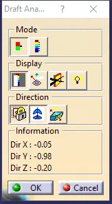
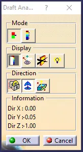
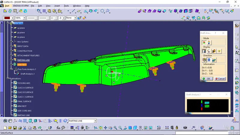
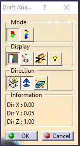
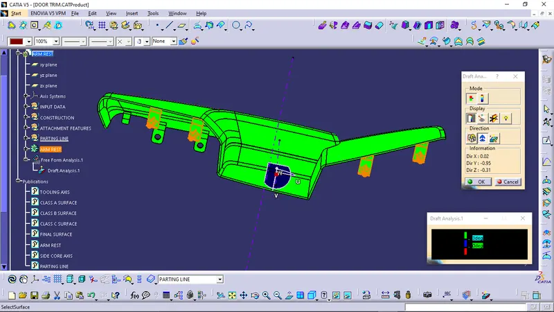
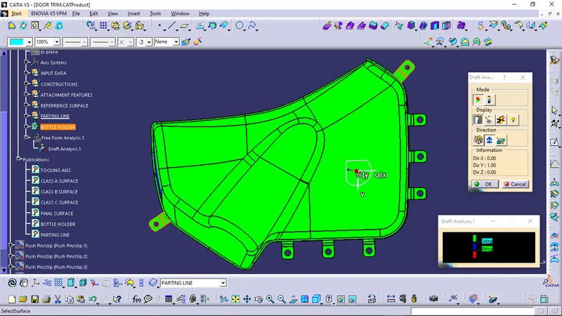
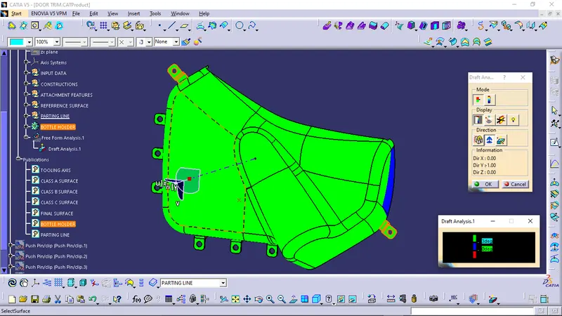
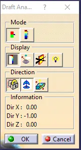
- After creation of all the components and its engineering and attachment features the draft analysis is carried out in order to check that proper draft angle is maintained in all the faces or not so that the part can be manufactured without any difficulty.
DRAFT ANALYSIS ON LOWER SUBSTRATE:
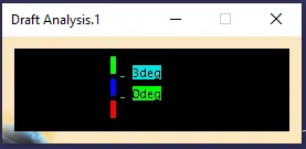
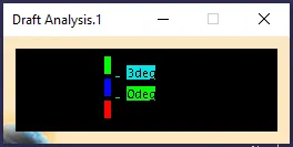
COLOR CODE:
- GREEN COLOR: For draft angle more than 3 degree.
- BLUE COLOR: For draft angle between 0 to 3 degrees.
- RED COLOR: For Negative draft angle.
ON CLASS A SURFACE:
ON CLASS B SURFACE:
DRAFT ANALYSIS ON ARM REST:
COLOR CODE:
- GREEN COLOR: For draft angle more than 3 degree.
- BLUE COLOR: For draft angle between 0 to 3 degrees.
- RED COLOR: For Negative draft angle.
USING MAIN TOOLING AXIS:
ON CLASS A SURFACE:
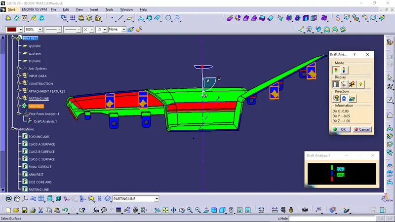
ON B SURFACE:
USING SIDE CORE AXIS:
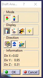
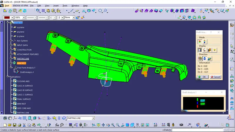
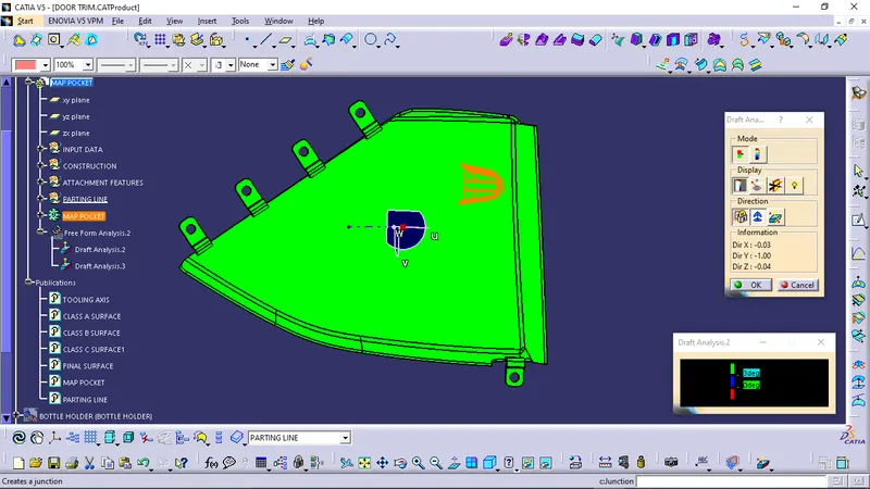
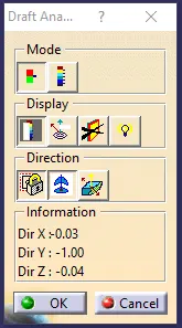
DRAFT ANALYSIS ON MAP POCKET:
COLOR CODE:
- GREEN COLOR: For draft angle more than 3 degree.
- BLUE COLOR: For draft angle between 0 to 3 degrees.
- RED COLOR: For Negative draft angle.
ON CLASS A SURFACE:
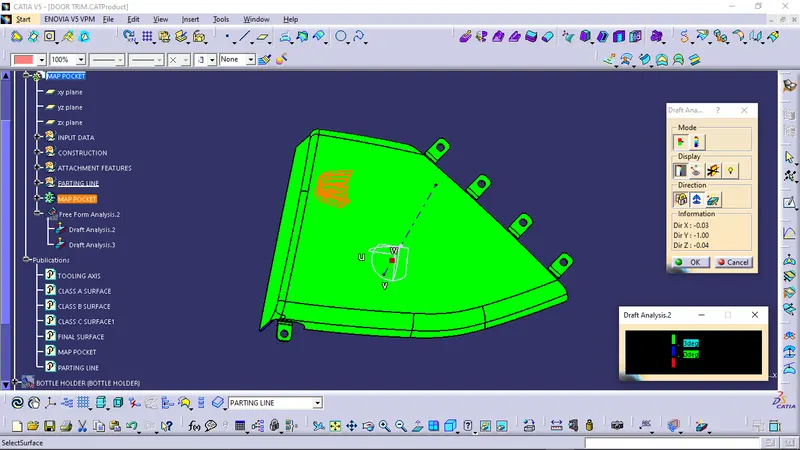
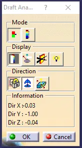
ON CLASS B SURFACE:
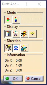
DRAFT ANALYSIS ON BOTTLE HOLDER:
COLOR CODE:
- GREEN COLOR: For draft angle more than 3 degree.
- BLUE COLOR: For draft angle between 0 to 3 degrees.
- RED COLOR: For Negative draft angle.
ON CLASS A SURFACE:
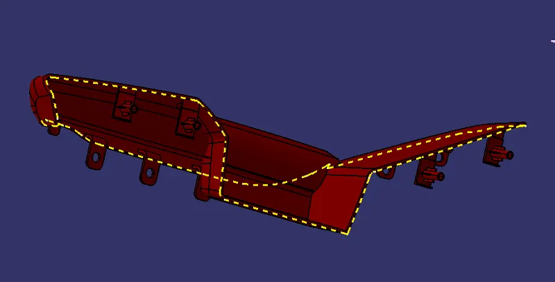
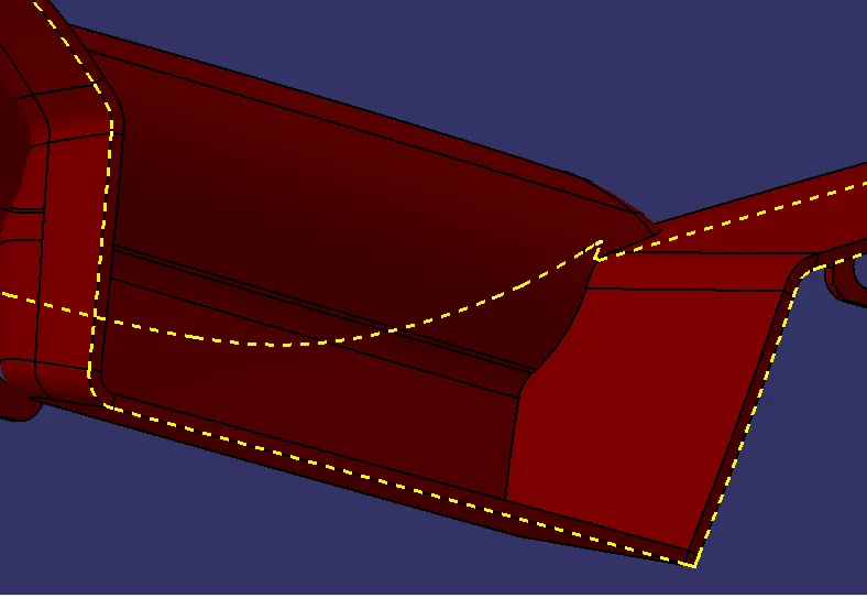
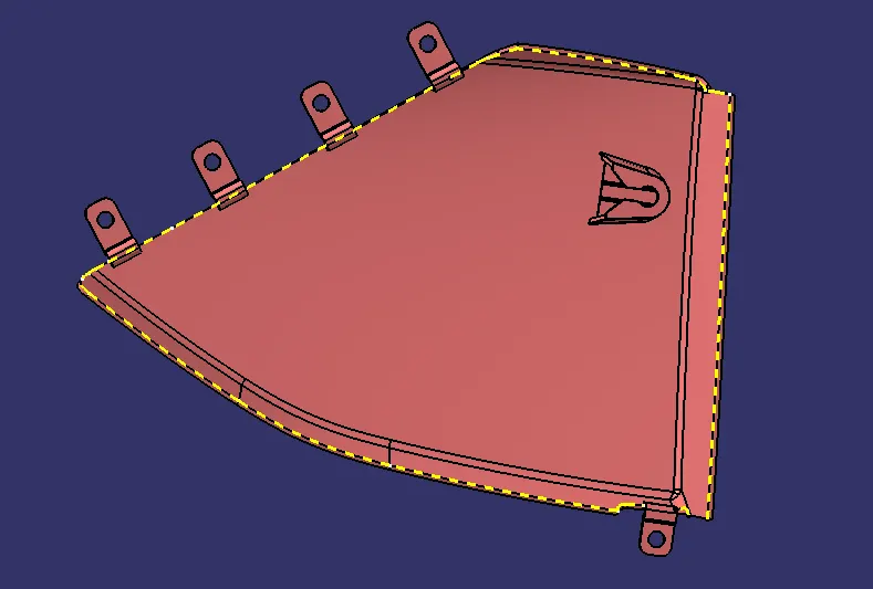
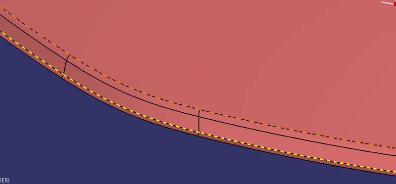
PARTING LINES:
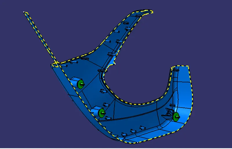
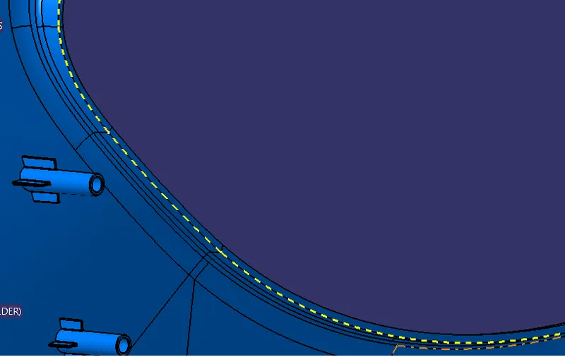
- It is the area where the parting surface meets the component.
- It is the junction between the core half, cavity half and the parting surface.
- The Parting line and the parting surface should always be present at the B surface because it is not visible to the customer and does not create any issues in the aesthetics.
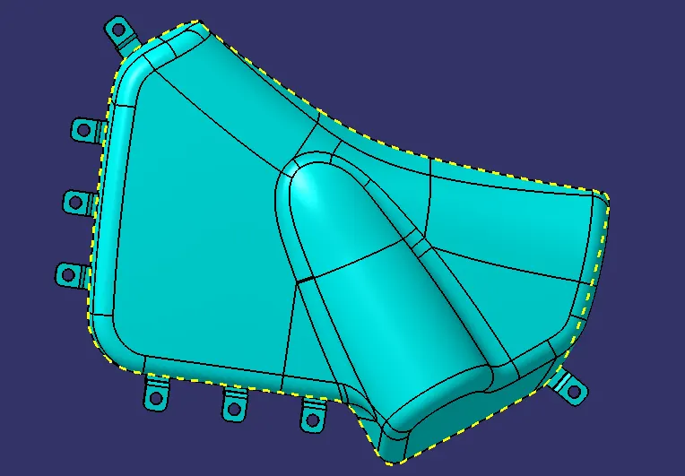
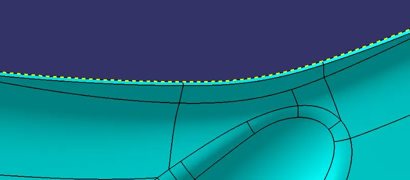
PARTING LINE ON LOWER SUBSTRATE:
PARTING LINE ON THE ARM REST:
PARTING LINE ON THE MAP POCKET:
PARTING LINE ON THE BOTTLE HOLDER:
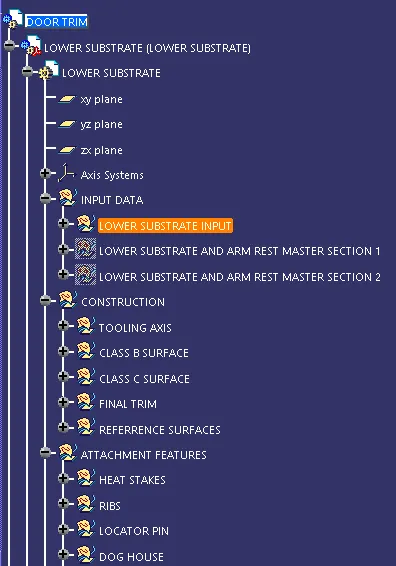
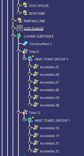
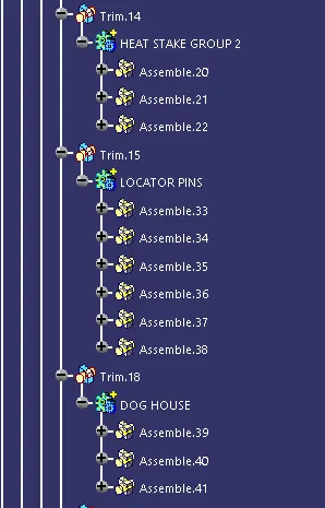
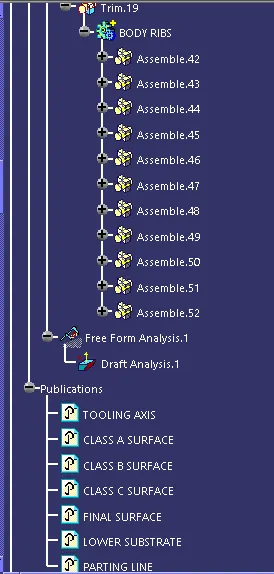
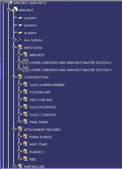
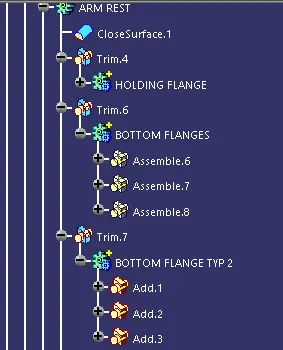
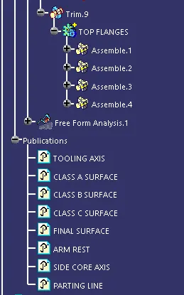
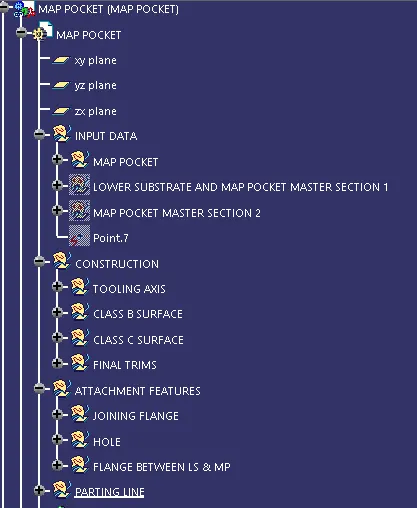
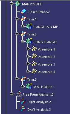
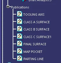
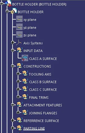
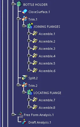
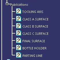
TREE STRUCTURE:
 '
'
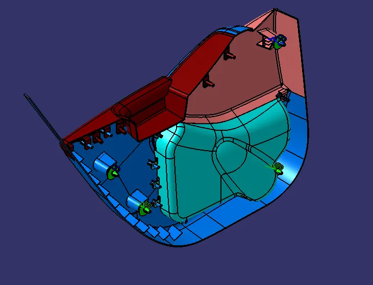
DIFFERENT VIEWS OF THE FINAL COMPONENT:
ISOMETRIC VIEW:
FRONT VIEW:
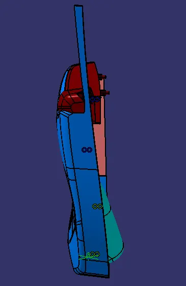
BACK VIEW:
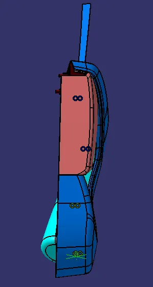
LEFT VIEW:
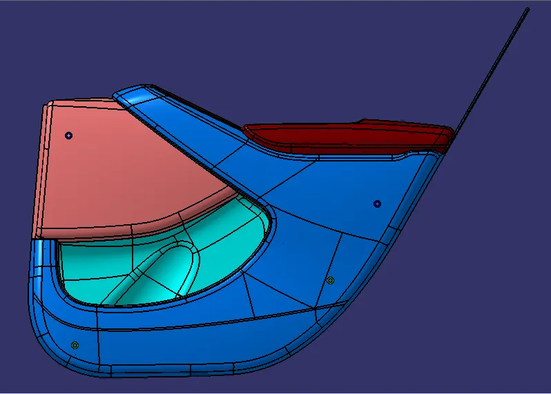
RIGHT VIEW:
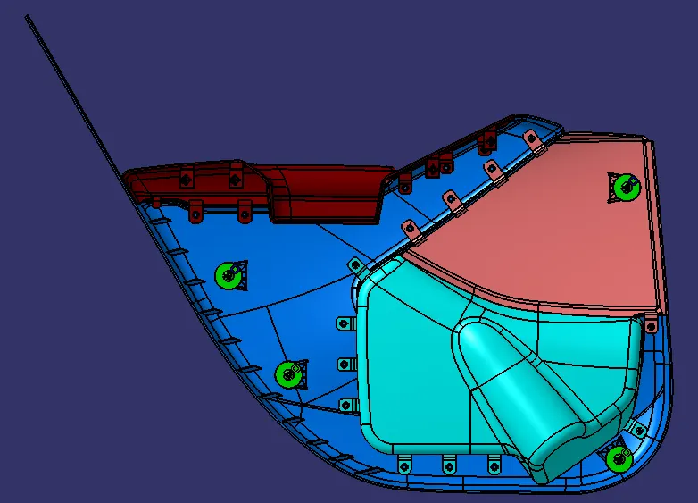
TOP VIEW:
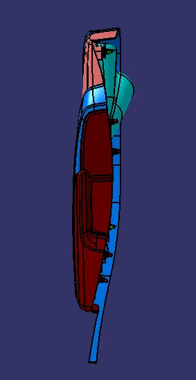
BOTTOM VIEW: