Week 11 - Final project
REPORT ON DESIGNING AND ASSEMBLING THE COMPLET DOOR TRIM PART WITH CLOSED BODY, B SIDE FEATURES AND PUSH CLIPS
INTRODUCTION
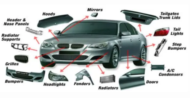
The car has many plastic components as shown below
The part we are going to design is the internal door panel which get attached to to sheet metal part of BIW of car door.
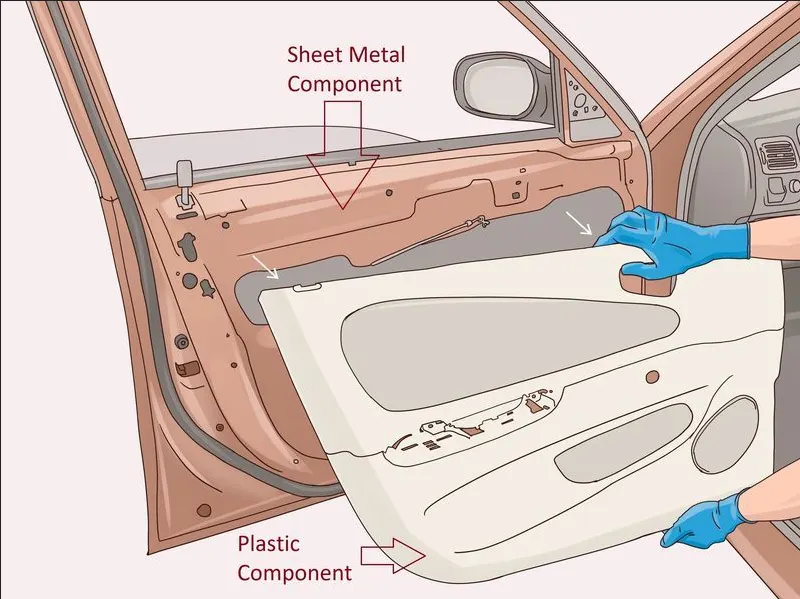
Door panels serve as an interface between the interior of the car and the inner workings of the door, and between vehicle occupants and the door. They are expected to meet a variety of design specifications regarding safety, aesthetics, and functionality.
In addition, they are expected to continue the material theme of the dashboard and pillars while concealing intricate electrical and mechanical components for operating locks, windows, and other features. The door panel has evolved from a simple two-part system of latch and simple winding mechanism to a more sophisticated enclosure. Doors currently have an inner full-width panel consisting of electronic windows, central locking system, and speakers. These panels typically consist of a foamed core covered with either textiles or plastics.
Door panels are expected to meet one of the toughest sets of requirements among interior car components. These panels should be designed to withstand and channel loads into the body of the car while being thin.
Conventionally, door panels consisted of polyvinyl chloride (PVC) or polyurethane foamed core with appropriate textile fabric coverings. Subsequently, there was a shift toward thin-wall moldings of ABS or PP backed by textiles in order to manufacture a contour-backed panel with recesses. This is primarily because integrated injection-molded door panel assemblies reduce the need for other energy-absorbing materials, resulting in cost reduction for manufacturers due to simplification of door construction. Currently honeycomb-based plastics are attracting attention due to their tougher, lighter, and better acoustic properties.
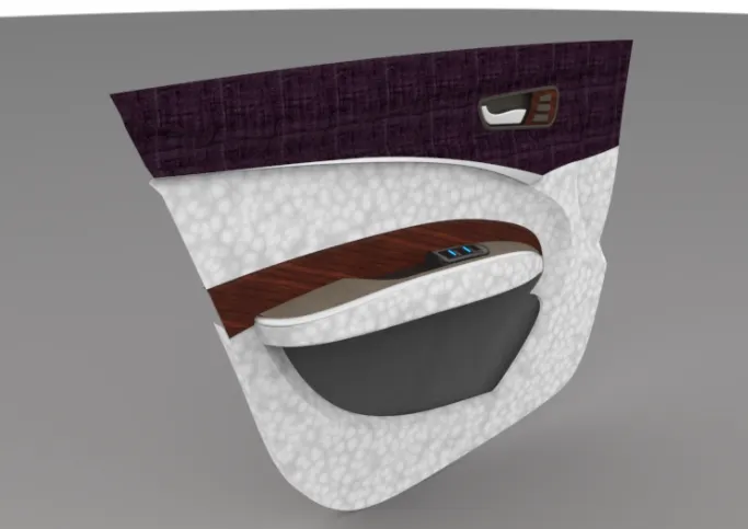
INTERNAL DOOR PANEL(PLASTIC COMPONENT)
DESIGN METHODOLOGY
- CLASS-A SURFACE
- CHECKING THE QUALITY OF CLASS-A SURFACE
- IMPROVING THE CLASS-A SURFACE IF REQUIRED
- CREATING THE TOOLING AXIS
- APPLING THE DRAFT ANALYSIS ON CLASS-A SURFACE
- PREPARING CLASS-B AND C SURFACES
- CREATING THE CLOSED BODY
- MODIFING THE CLOSED BODY ACCORDING TO THE GIVEN MASTER SECTIONS
- CREATING THE B SIDE FEATURES (LOCATOR, HEATSTICKS, DOG HOUSE, )
- DRAFT ANALYSIS ON THE COMPLETE PART (WITH TOOLING AXIS AND LIFTER AXIS)
- ASSEMBLING ALL PARTS
DESIGNING PROCEDURE
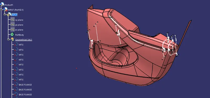
We are provided with the CLASS-A Surfaces and master sections of the complet door trim part.
So here I have created the seperate part files for all CLASS-A Surfaces of the part given
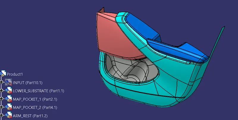
It is the given Class A-Surface
firstly tooling axis is prepared for thid class A-Surface.
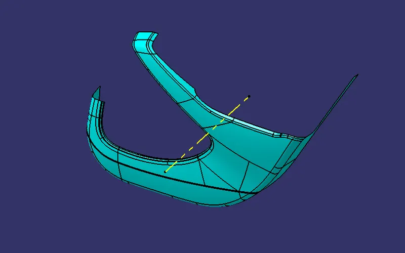
First a dummey tooling axis is made for the part.
Then made a draft analyis on the part with this tooling axis.
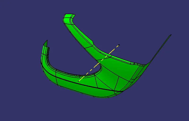
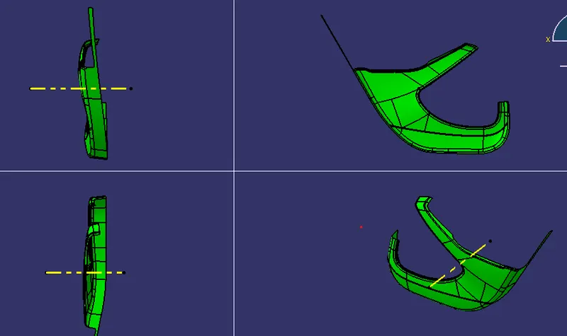
If this tooling axis clears the draft analysis then it will be our main tooling axis.
Make sure all other parts will have approx same tooling direction so that it will be easy for the assembly of the B-Side features.
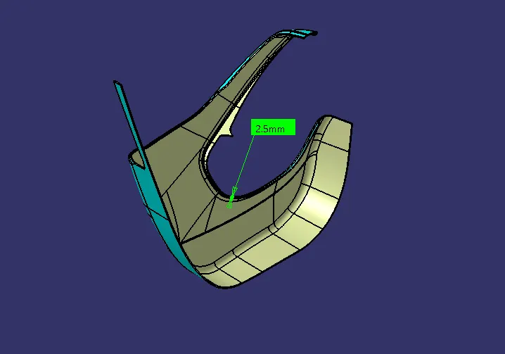
Making of CLASS-B Surface.
making of CLASS-C Surface.
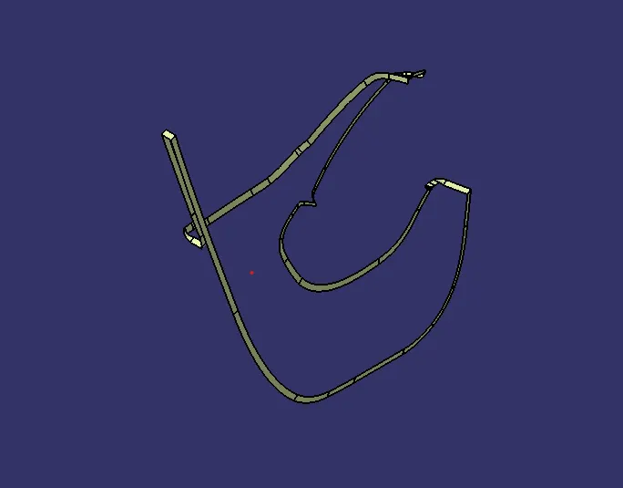
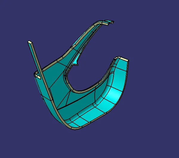
Initial sweeps from CLASS-A, Joining them with CLASS-A, Triming them with CLASS-B, Then here is our final CLASS-C.
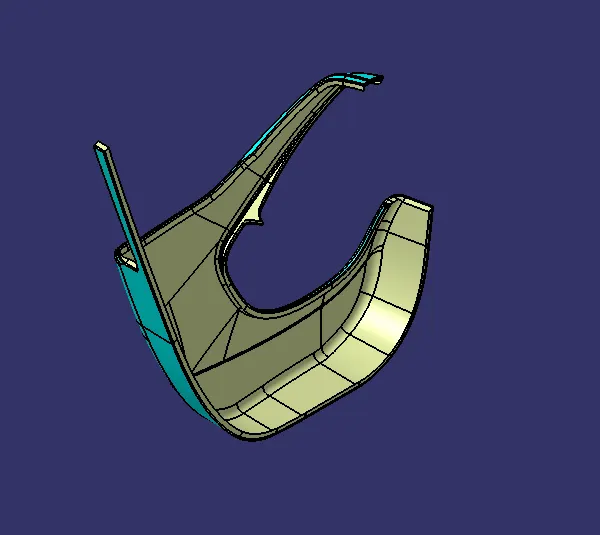
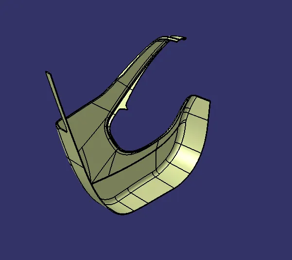
Making a closed body with CLASS-C.
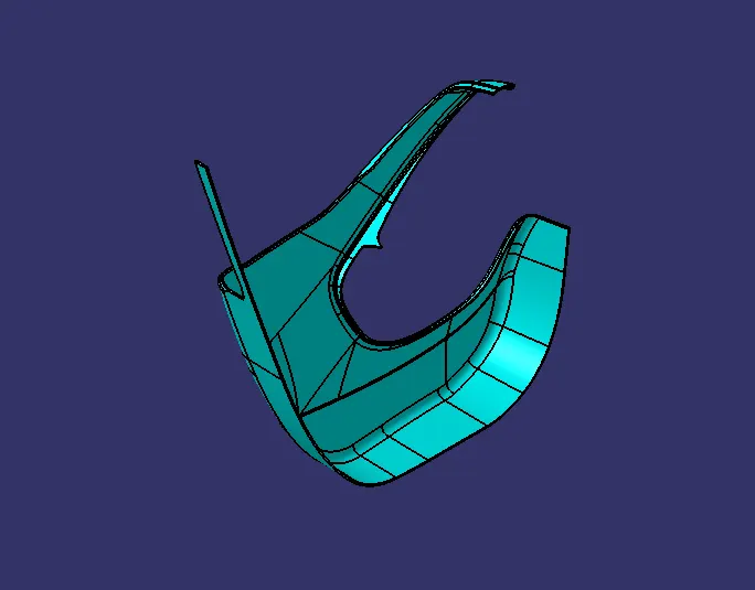
Then draft analysis on the closed body.
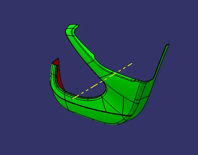
Creating the flanges according to the given MASTER SECTION.
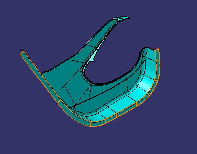
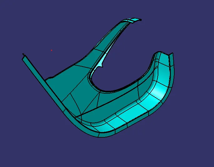
Now its time for the second part in the door trim panel.
MAP POCKET 1 PART
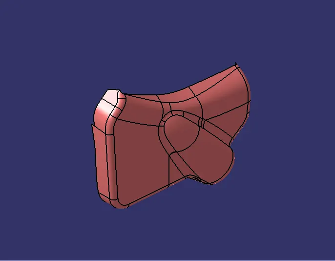
The seme procedure is folled for all the parts as shown for the first part.
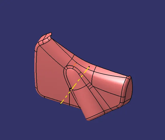
TOOLING AXIS
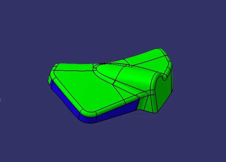
DRAFT ANALYSIS
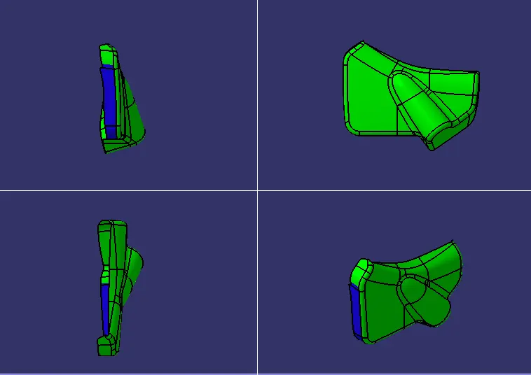
As some area is not clearing the the draft analysis with the minimum of 3deg draft.
the Blue colour area shows it has the angle between 0-3deg.
So we are here to develop the CLASS-B and C, and B-Side features so we can't make any changes in CLASS-A.
In this case this shouid be reported to the CLASS-A Designer or Developer.
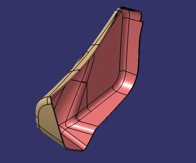
CLASS-B
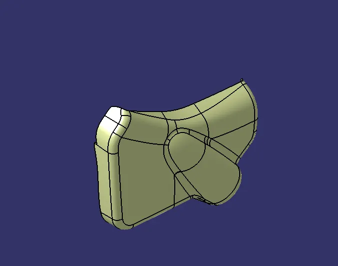
CLASS-C
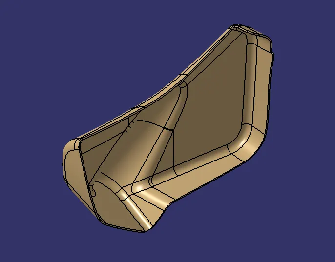
CLOSED BOPDY
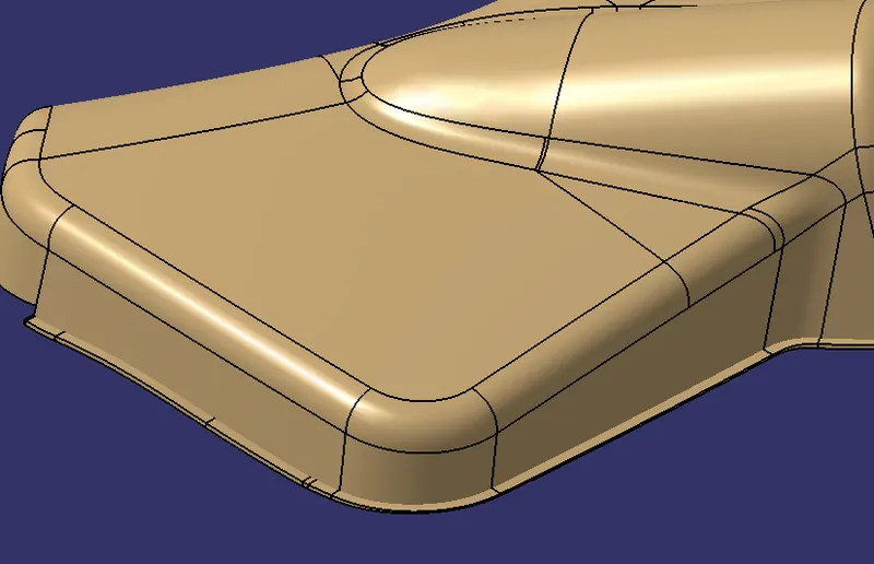
FLANGES
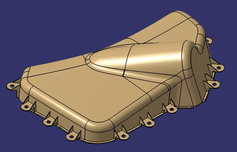
HEAT STICK FLANGES
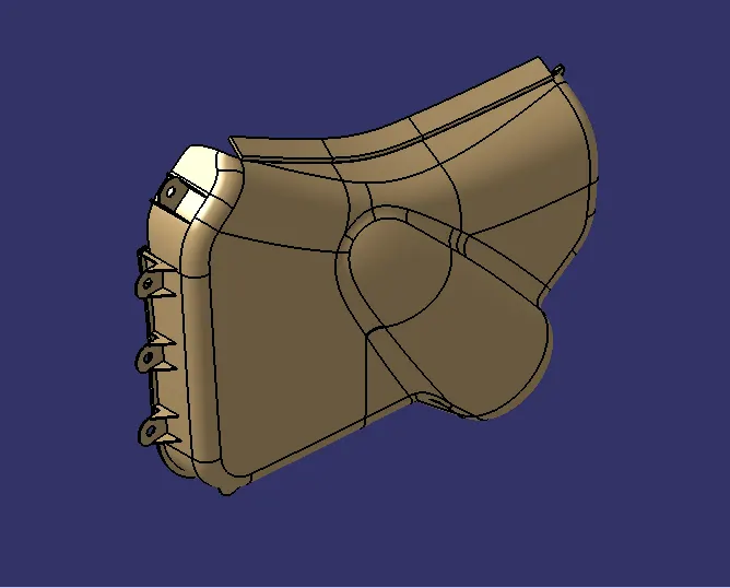
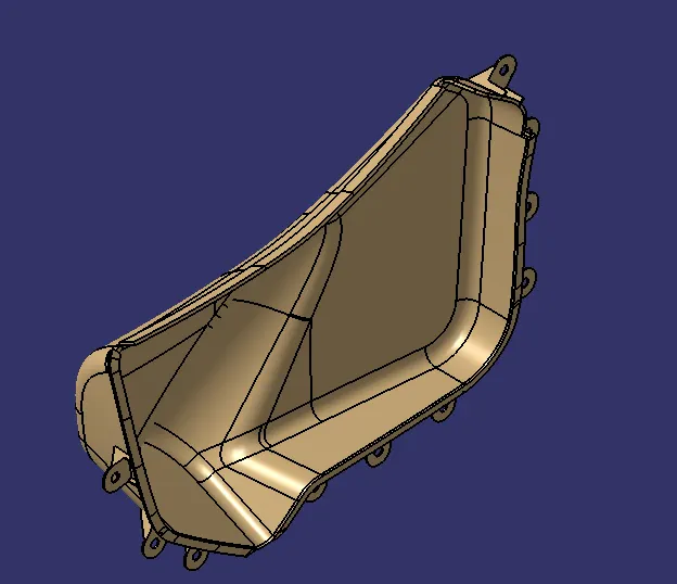
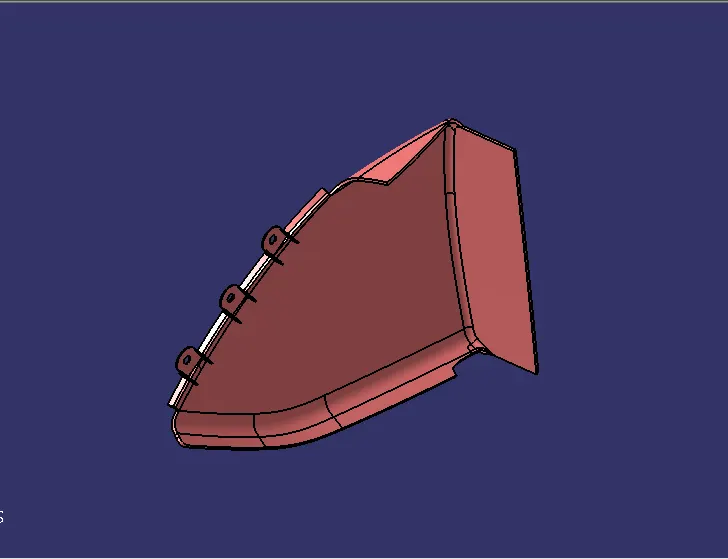
FINAL MAP POCKET 1 PART.
MAP POCKET 2
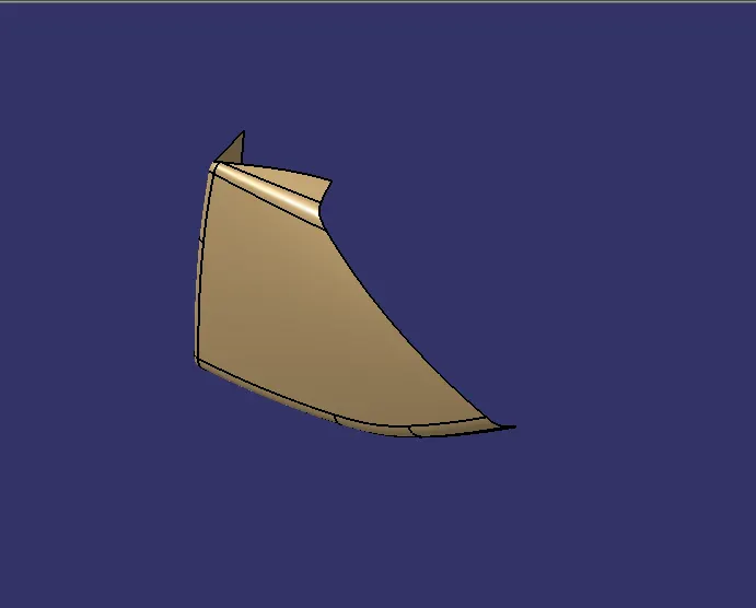
CLASS-A
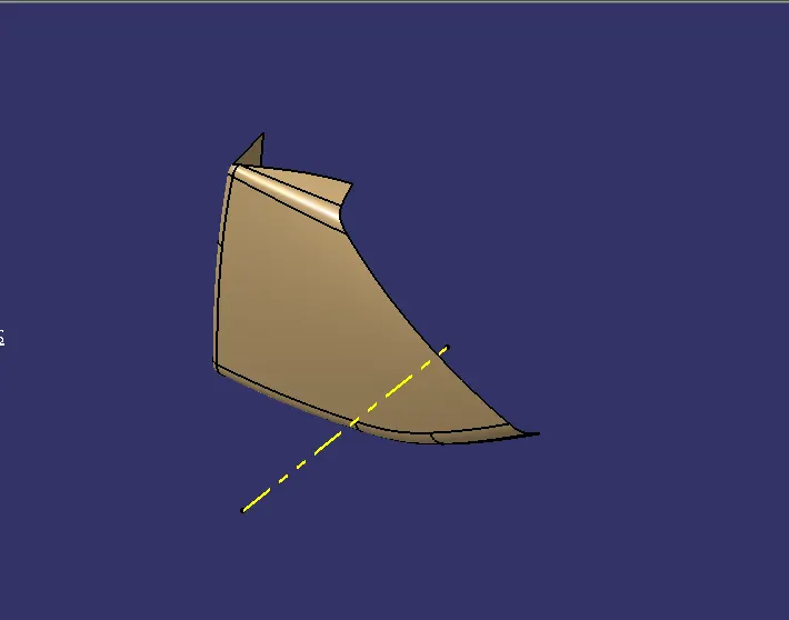
TOOLING AXIS
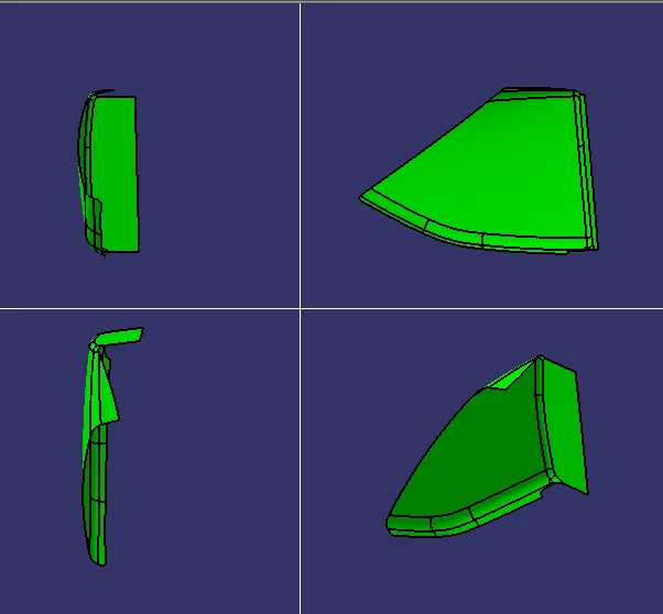
DRAFT ANALYSIS
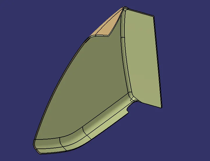
CLASS-B
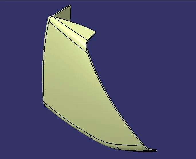
CLASS-C
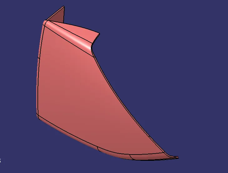
CLOSED BODY
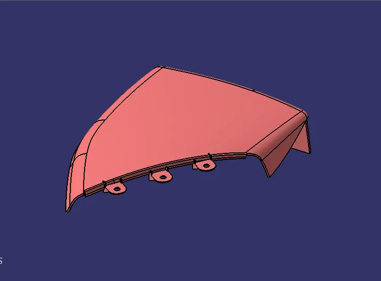
HEAT STICK FLANGES.
FINAL MAP POCKET 2 PART.
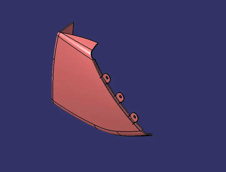
DOOR ARM REST PART.
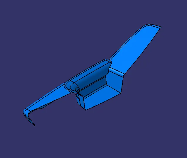
CLASS-A
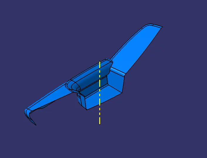
TOOLING AXIS
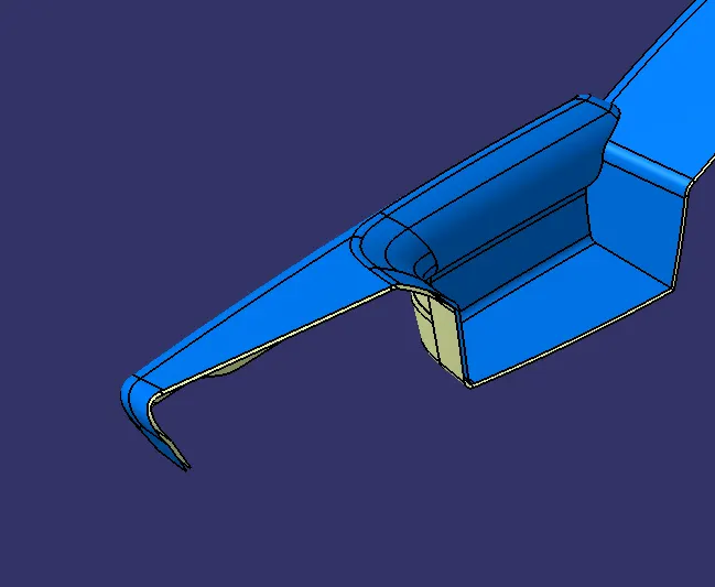
CLASS-B
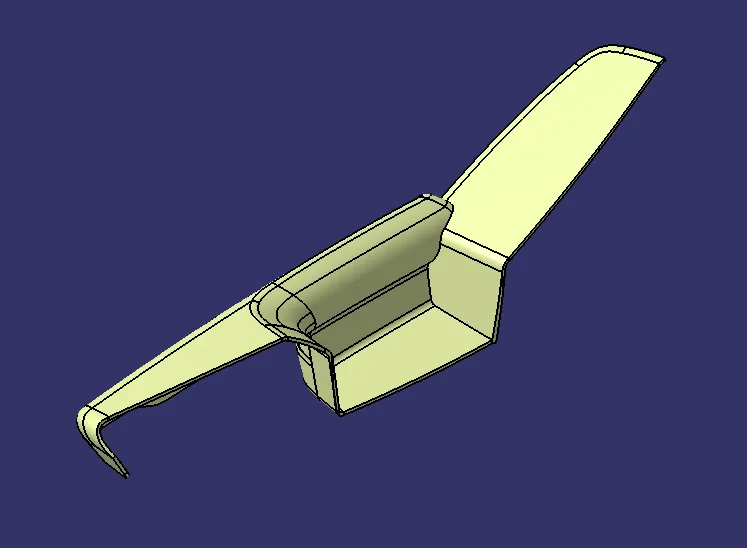
CLASS-C
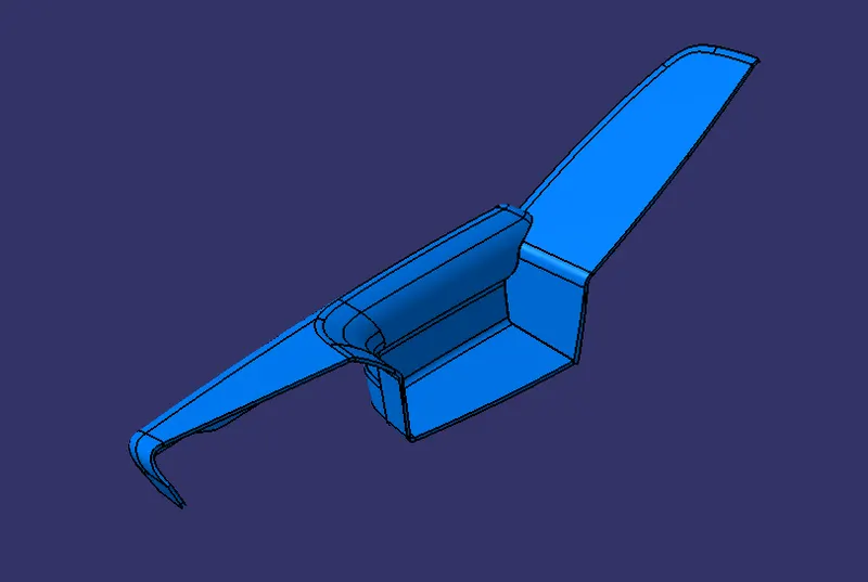
CLOSED BODY
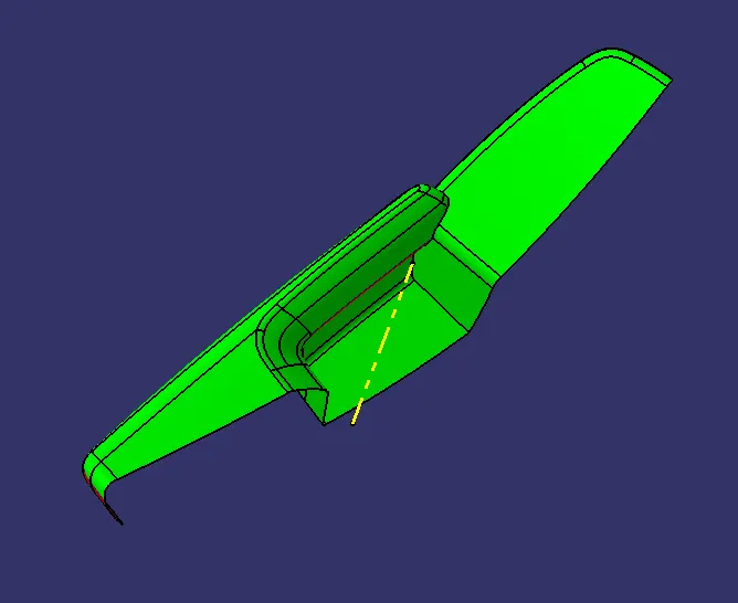
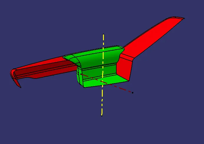
DRAFT ANALYSIS
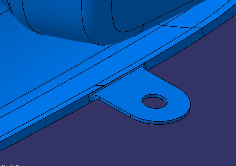
HEAT STICK FLANGES
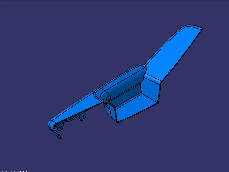
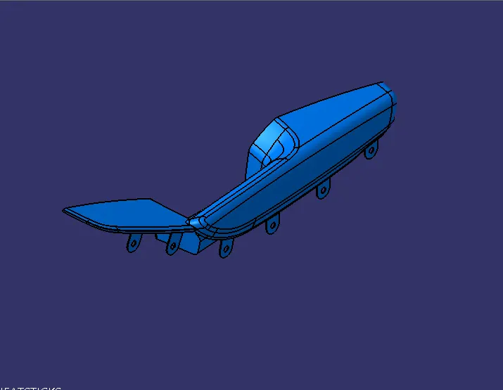
FINAL ARM REST PART.
Now HEAT STICKS are created according to the flanges on the other parts.
And the DOG HOUSES are created for the HEAT STICKS if the length of the HEAT STICK is too long.
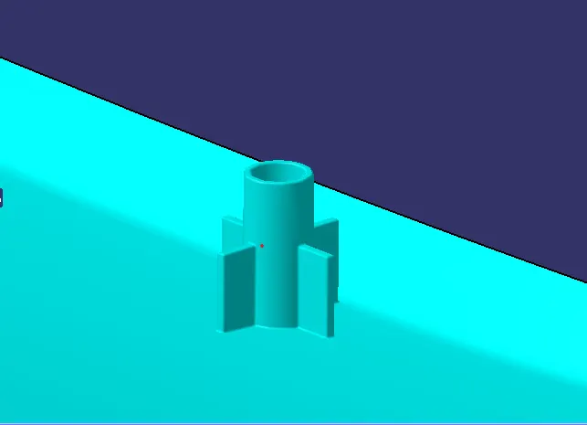
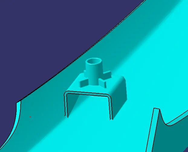
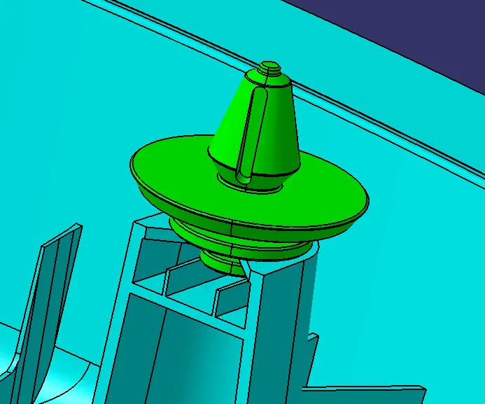
DOG HOUSE for the PUSH CLIPS
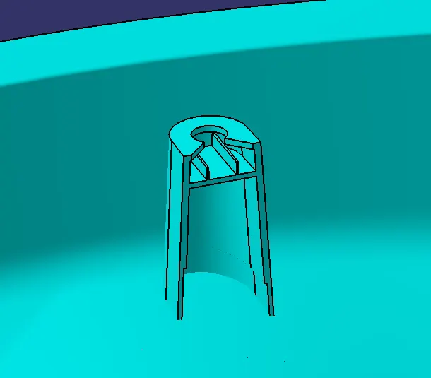
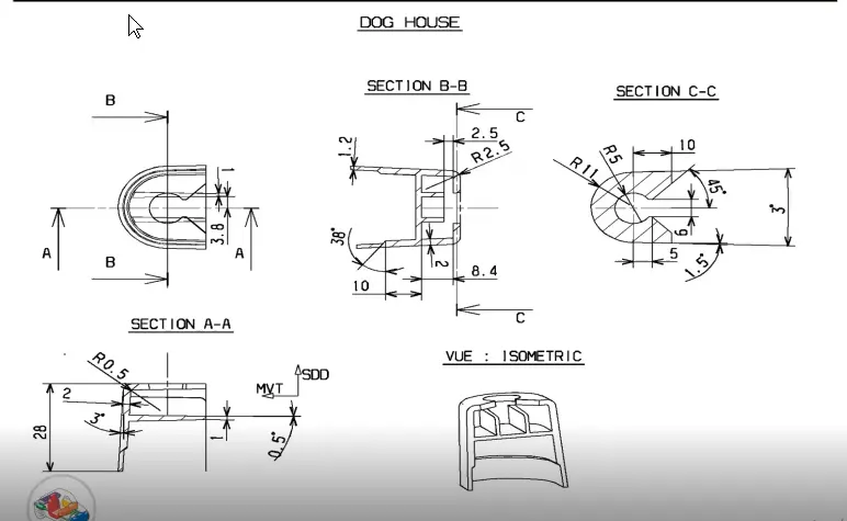
The DOG HOUSE is created according to the given standards.
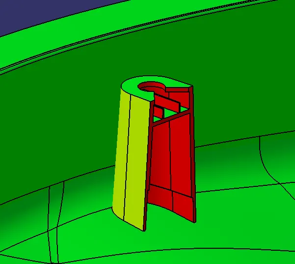
Draft analysis with the main tooling axis.
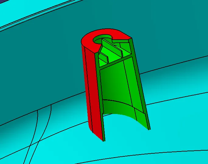
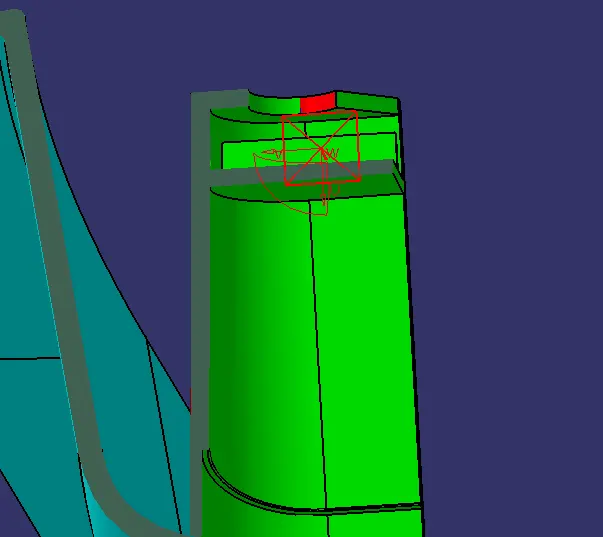
Draft analysis with the lifter axis.
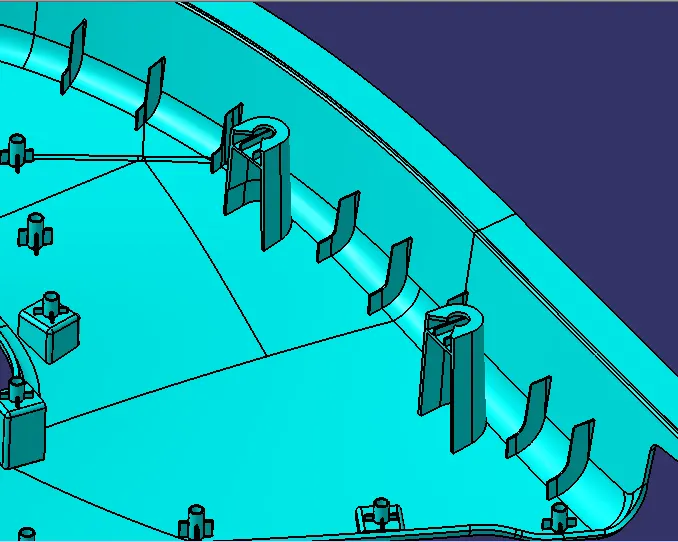
RIBS are created at the edge of the LOWER SUBSTRATE Part.
It has two main reason
1.It gives strength to the part
2.Less damage to the part while removing the part from the mould dies.
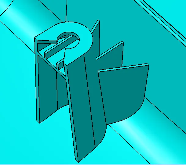
RIBS for the DOG HOUSE it supports the dog house
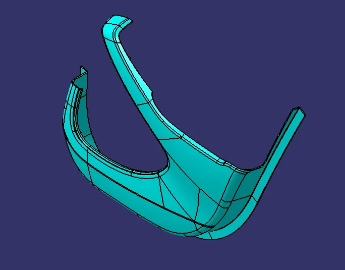
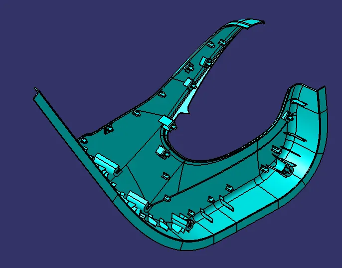
Final LOWER SUBSTRATE part.
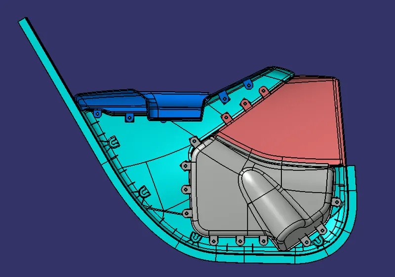
ASSEMBLING ALL PARTS OF THE DOOR TRIM
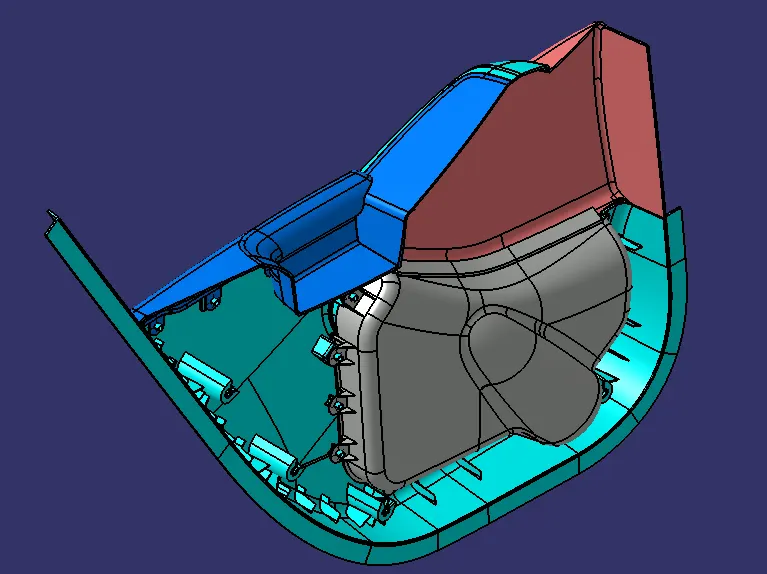
PUSH PINS
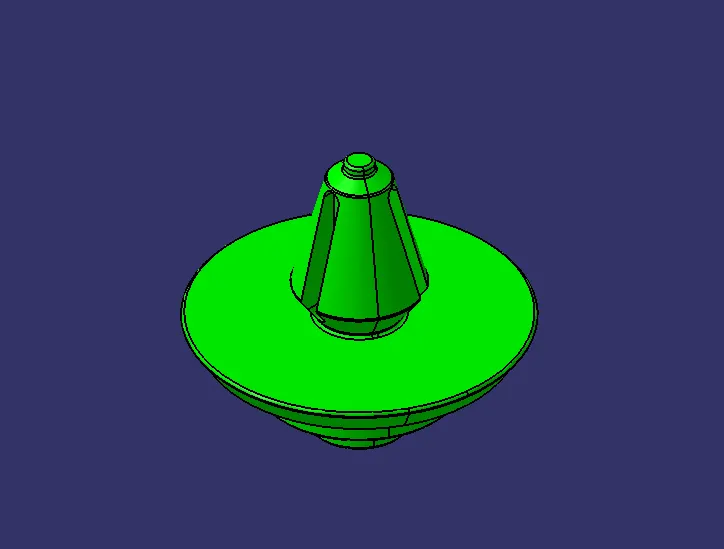
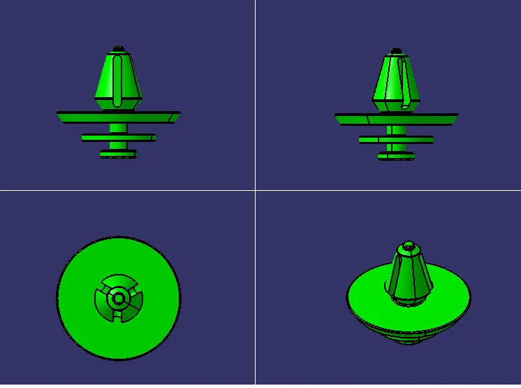
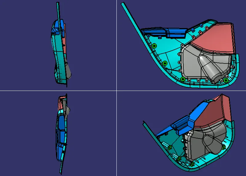
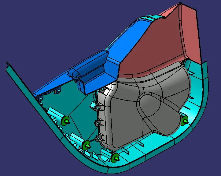
ASSEMBLING THE PUSH CLIPS ON THE DOG HOUSES
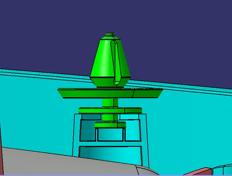
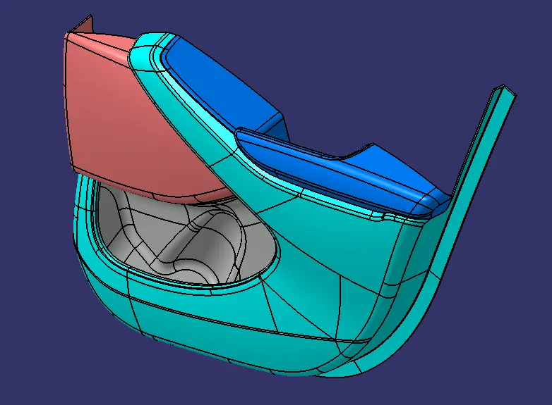
FINAL ASSEMBLY OF THE DOOR TRIM
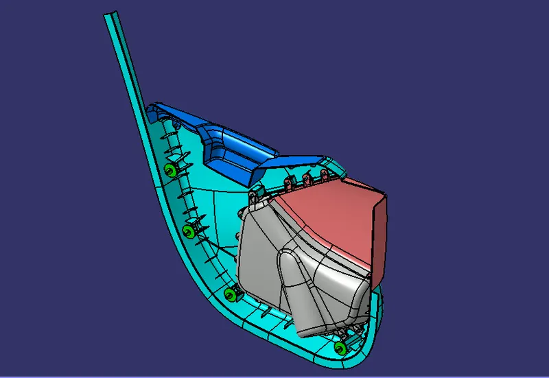
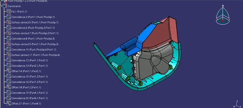
CONSTRAINS GIVEN TO THE ASSEMBLY OF THE DOOR TRIM