Week 11 - Final project
AIM - To create the Door trim panel's CAD model considering the inputs given to me following the design rules and OEM standards.
ABSTRACT - The project is about explaining the stages and techniques taken when designing a car's Door Trim Pancl in CATIA V5. I was able to generate the tooling axis, class B surface, and class C surface using the class A surface, and after making the solid body from that, I was able to create the flanges and B side features like Dog house, push pins, Heat stakes, and so on. Finally, the components are subjected to a draught analysis in order to determine their manufacturability.
INTRODUCTION - In most cases, the door panel will match the rest of the vehicle's interior. Previously, door panels were constructed of cardboard with an upholstered inner finish of vinyl, leather, fabric, carpet, or other materials. Modern cars generally have door cards constructed of plastic and combining various decorative elements, most often via injection moulding. Both the required servicing quantity and the functional unit (such as a computer) should be included in the design "It is strong" and it looks and feels good"), ensuring that a certain car door panel will last for 200,000 kilometres (124,274 mi). "Other parts that add to the vehicle's aesthetic, functionality, and ergonomics are usually included in the door panel. Armrests, switches, and various window and locking mechanism controls are examples. Various features include map pockets, a lower substrate, storage compartments, and other convenience lights. An image of the door trim panel is shown below:
The steps that I followed for this project is mentioned below:
1) Extracting the class A surface from the input.
2) Draft Analysis of class A.
3) Creation of Class B and Class surface from Class A.
4) Created the solid body and performed the draft analysis on the solid body.
5) created the flanges.
6) Created the Engineering features
7) Draft analysis of the component with Engineering features.
PROCEDURE - Here the input which is given to me is below:
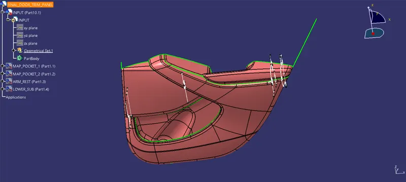
In the above fig., u can see that the surfaces along with the master section are given to me.
Master section - The directions for a design that moulds the component following technical styling of a class A surface are included in the master section. The Master section is a parameterized model of the vehicle body that lays out the NPD team's guidelines.
As a result, I'll have to produce three pieces, as listed below:
1) Lower substrate
2) Map pocket
3) Door Armrest
Then I have to design the attachment features that are needed for the parts to be assembled.
First, I began by constructing the lower substrate. I did this by extracting the class A surface of the lower substrate from the given input.The extract is shown below:
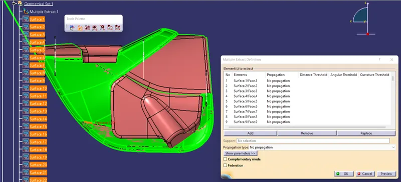
The class A surface of the lower substrate is shown below:
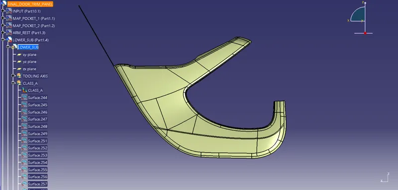
The additional section of the class A surface was then split by drawing a line and splitting it with the split feature in generative shape design. so the final class A surface is shown below:
Now I have to perform the draft analysis on the class A surface. For the draft analysis, I need a tooling axis for this lower substrate.
Tooling axis - The tooling axis is the direction in which the mould, as well as the core and cavity, open and close. The correct tooling axis must be chosen to ensure that the component is removed perfectly and that the component's cost is minimised. To begin, I'll insert a geometrical set and name it a tooling direction. For the tooling axis, I will evaluate the model and determine from which direction I can see the entire model; so, the direction I have chosen for the tooling axis is along the y-axis because the entire model is visible along the y-axis. To make the tooling axis, I'll draw a point on the lower substrate and then draw a line along the y-axis from that point. That line will be my tooling axis.The tooling axis is shown below:
After creating the tooling axis I have done the draft analysis on the lower substrate.
Draft analysis - Draft analysis is a technique for determining whether or not a component is manufacturable based on the drafts circumstances used. So, in this section, I'll show you how to eject the component so that it may be easily removed. The tooling axis that I have defined will be my direction. The minimal draft value for automotive plastic components is 3 degrees, while 7 degrees of draft is adequate for texturing faces. In the case of plastic components, the draft is delivered to the component for easy removal from the mould.
So I'll adjust the customizable view parameters and choose the material mode here.
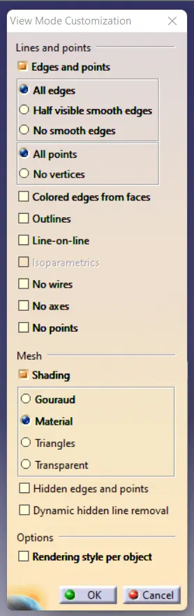
Then I'll go to insert and choose the analysis, and then I'll select the draft analysis within the analysis.
Under the display section of the above fig., I will select the colour scale and turn on the right effect for proper visualisation, then under the direction section, I will click on the compass and drag it from vehicle zero to my tooling axis, and finally, under the lock feature, I will select the class on the surface.
The result is shown below:
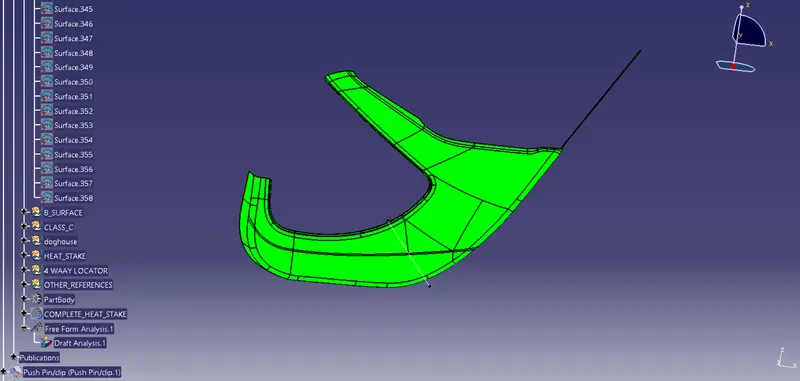
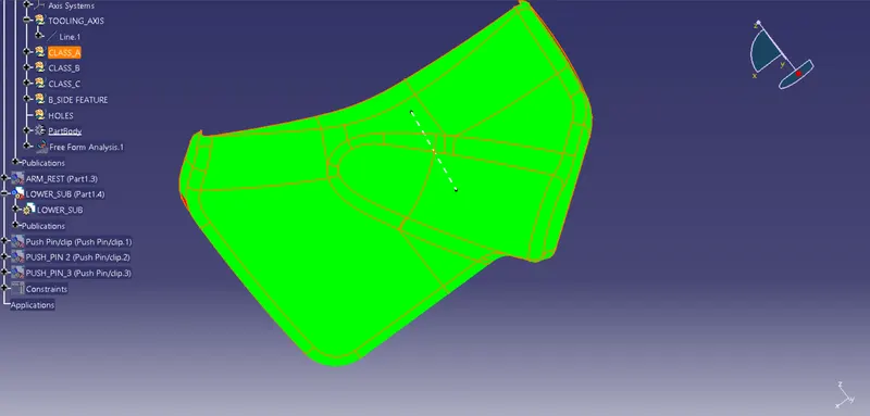
The color scale shown above denotes the following:
The colour green indicates that the draft provided is higher than 2.9 degrees.
The draft provided is between o and 2.9 degrees, as indicated by the blue tint.
The draft presented is negative, as indicated by the red colour.
After completing the draftanalysis, I verified that the component has the right draft, and I am now ready to generate the Class B and Class C surfaces.
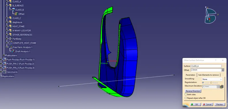
Class B surface - It's a surface that takes the thickness of a class A surface and adds it to it. All of the component's supporting features will be produced solely on the B surface. As a result, Class B can be classified as an engineering surface, while Class A can be classified as an aesthetic surface. I offset the Class A surface to 2.5 mm for the Class B surface, which is the thickness of the part according to the master section that is provided as input. The offset is shown below:
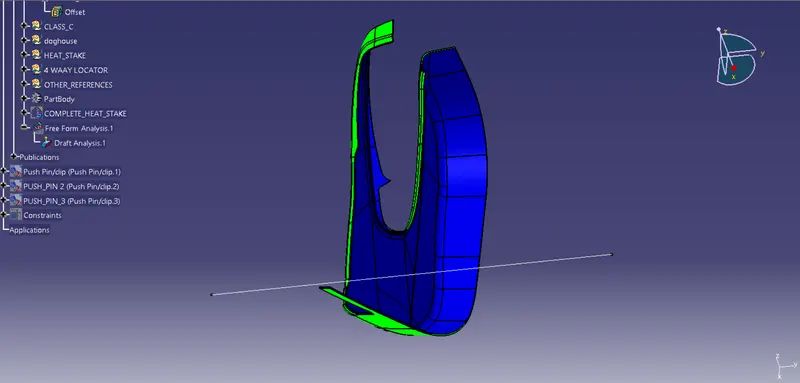
After offsetting the class A surface to 2.5 mm I have extrapolated the class B surface up to the extent to which it can be trimmed later with the class C surface. The Final extrapolated B surface is shown below:
CLASS C SURFACE - The surface that joins the CLASS A and CLASS B SURFACE along the tooling direction is known as the CLASS C SURFACE. My tooling axis will be the tooling direction here.
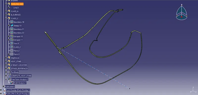
To make Class C, I took the limits of the Class A surface and swept them down the draft direction, resulting in a 3 degree draught. I also smoothed the swept surfaces with the smooth curve feature. For the parts that don't require a sweep with draft direction, I've also used the reference surface option in sweeping. The sweep parameters are shown below:
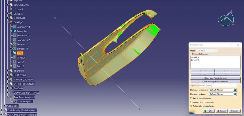
Then finally I have trimmed the Join of class A and class C with class B surface to get the required part. The trim is shown below:
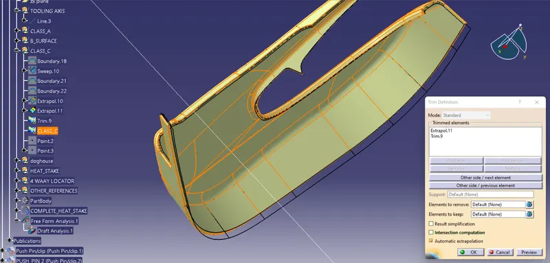
Then, after generating, I double-checked that I had a flat surface. So I had to utilise the boundary option to validate that, and when I clicked on the surface, I got an error, proving that I had a closed surface.The closed surface is shown below:
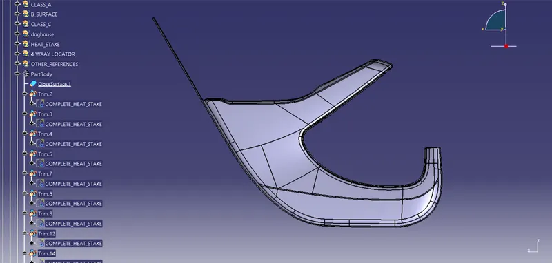
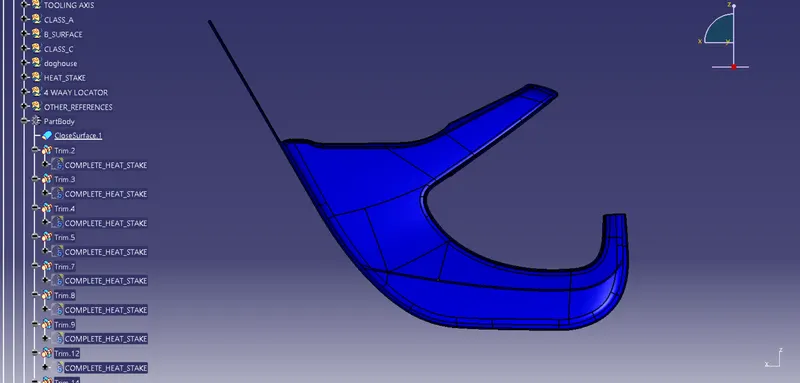
After this, I have created a solid body from this closed surface by using the close surface feature in part design. The solid lower substrate is shown below:
Then I have performed the draft analysis on the solid part. The draft analysis is shown below.
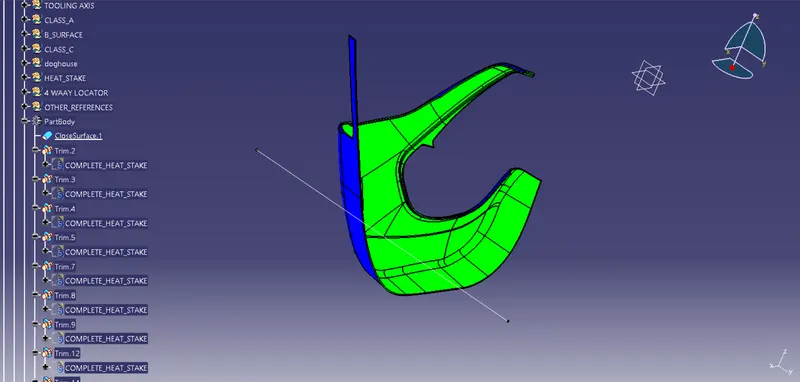
Now after creating the lower substrate I have created the map pocket. For the map pocket, I have divided it into two parts one is the inner map pocket and the other is the outer map pocket.
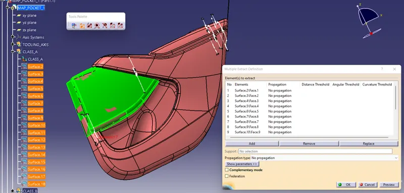
Outer map pocket - I started by making the outside map pocket using the same techniques as the lower substrate. As a result, the outer map pocket surfaces are extracted from the input. The numerous extracts, as well as the class A surface for the outer map pocket, are presented below.
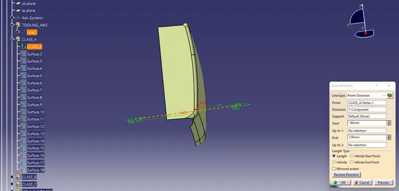
Tooling axis - I generated a point on the surface for the tooling axis, and from that point, I created a line that represents the tooling axis for the outer map pocket. The tooling axis is shown below:
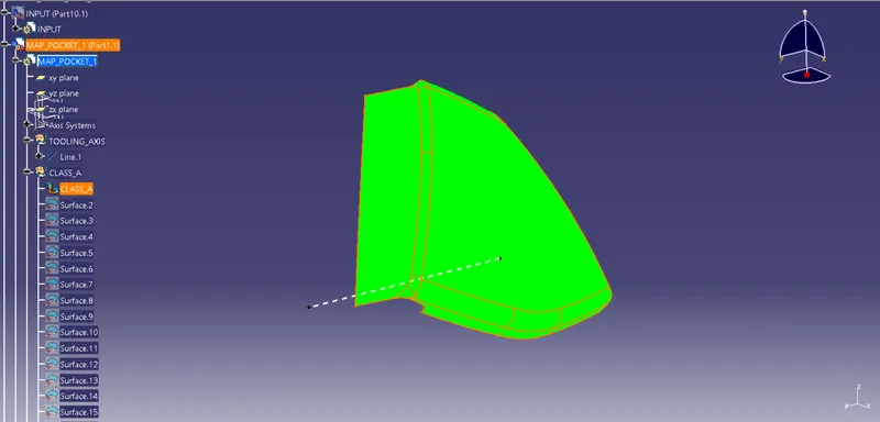
Now the draft analysis on the class A surface is sown below.
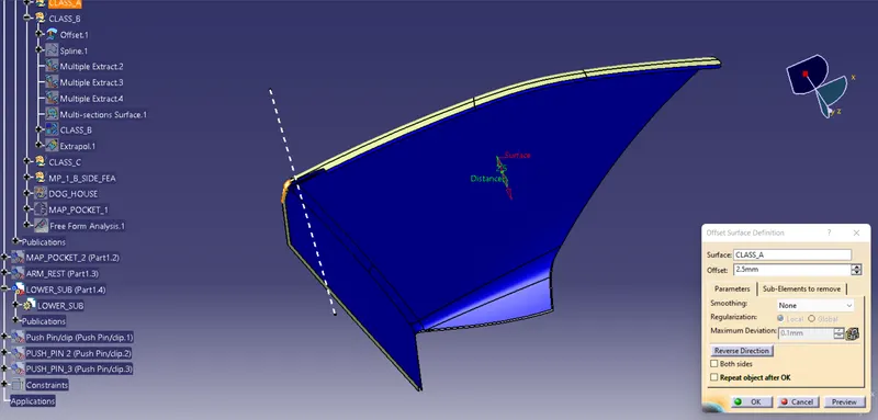
Class B surface - Now for the class B surface again I have just offset the class A surface to 2.5 mm. The offset is shown below:
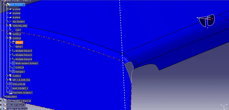
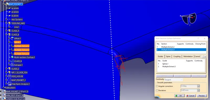
The offset that I got was not proper and it had some gaps so I filled that gap using the multisection surface feature in generative shape design. The multisection surface is shown below:
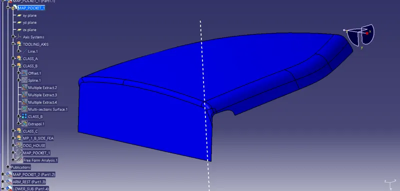
Then I have joined the multisection surface with the offset to get the class B surface. The final class B is shown below:
Class C surface - I blended the boundaries of the class A and class B surfaces together to create the class C surface. I gave the edges of A and B smooth curves before blending them together. The blend is shown below:
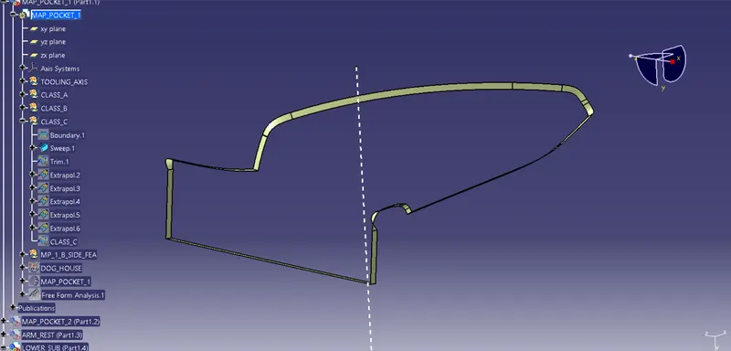
Finally I have trimmed the extrapolated surfaces together to get the part with a closed surface. The closed boundary is shown below:
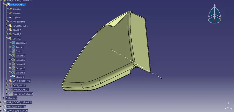
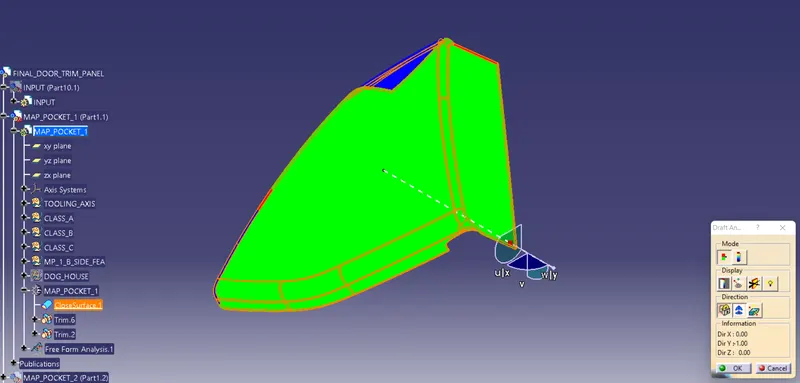
Then I have performed the draft analysis on the solid part the draft analysis is shown below.
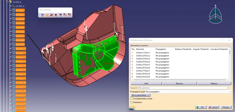
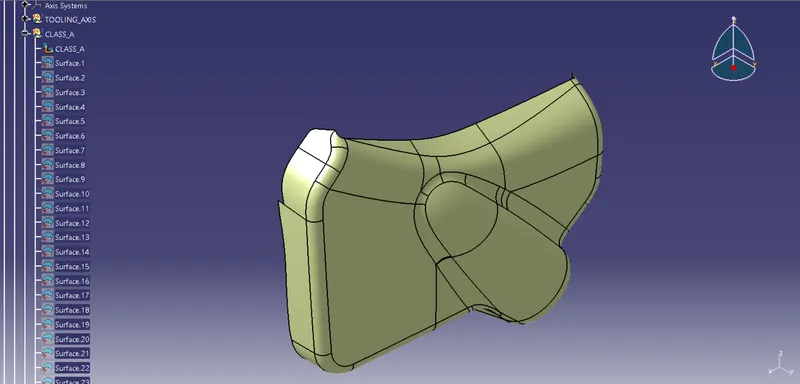
Inner map pocket - I followed the identical steps for producing the inside map pocket that I did before. As a result, the surfaces that make up the inner map pocket are extracted. The extracted surface is shown below:
After multiple extracts, the surface I got was a class-A surface of the inner map pocket. The class A surface is shown below.
Now I have performed the draft analysis on the class A surface. But before that, I have created the tooling axis
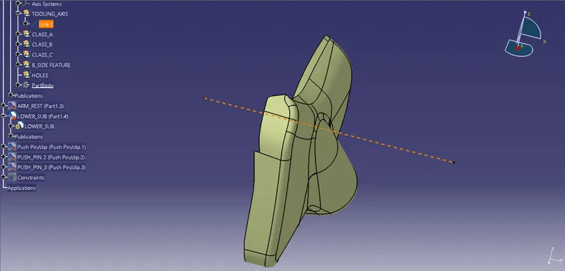
Tooling axis - I used the same approach for generating the tooling axis, which involves making a point on the class A surface and drawing a line from that point in the direction where class A is plainly visible.The tooling axis is shown below:
The draft analysis is shown below:
Now I have created the other two surfaces.
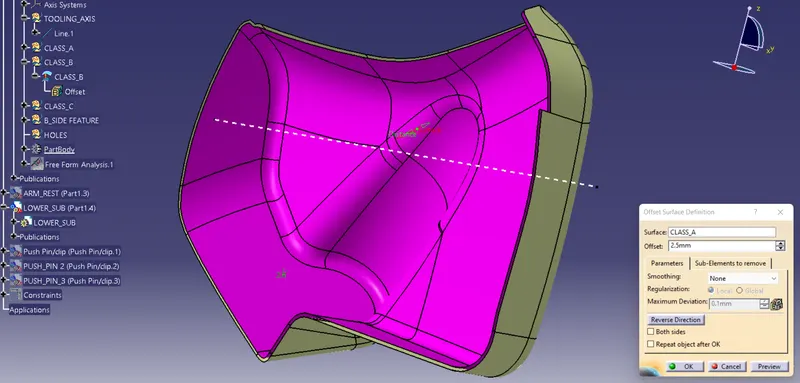
Class B surface - For class B again I have offset class A to 2.5 mm. The offset is shown below:
Class C surface - For creating the class C again I have swept the boundaries of class A using the 'with reference surface' option in the sweep command. And I have swept the boundaries to 87 degrees with the reference surface of the boundaries. The sweep parameters are shown below.
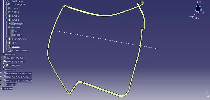
Then I have joined the Class A and Class C surfaces.
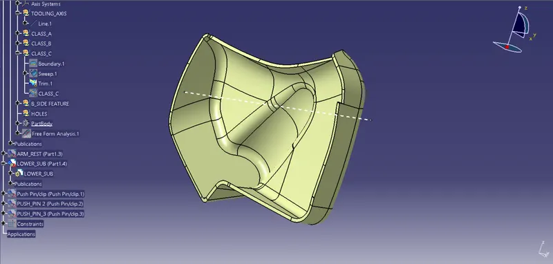
Then, after extrapolating the class B wherever it's needed, I cut the connect of A and C with class B surface. By drawing a boundary on the surface after generating the part, I was able to determine whether it was closed or not. It displayed an error, indicating that the surface is closed.The Trim is shown below:
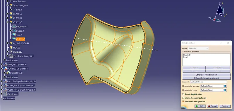
The closed surface is shown below:
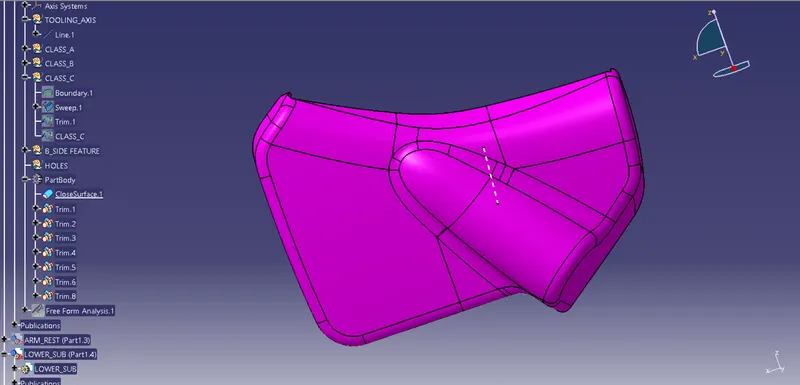
Then I have performed the draft analysis on the solid part. The draft analysis is shown below:
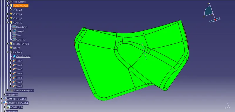
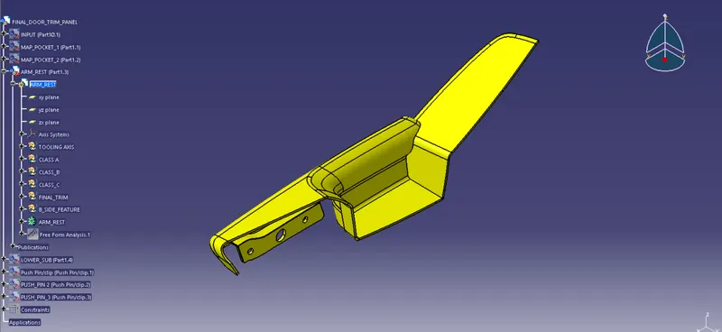
I made the door armrest after finishing the solid elements for the lower substrate and map pocket. For the Door Armrest, I divided the portion into two parts and renamed one as the door armrest cushion part and the other as the door armrest.
Door Armrest - For this again I have to first extract the class A surface from the input given. The multiple extracts are shown below:
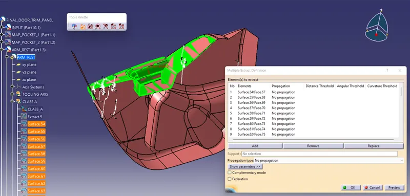
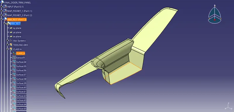
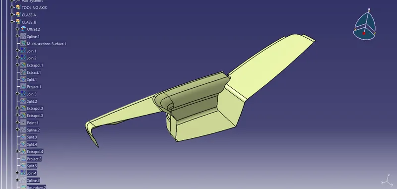
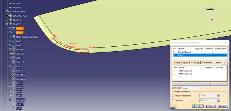
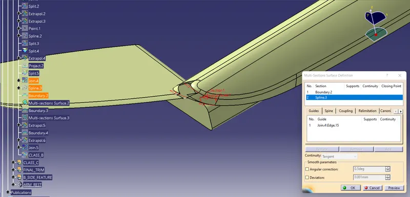
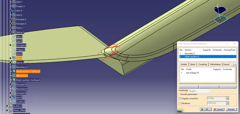
After ofsetting the surface I got the class B surface but there was a gap, so I filled it with the multisection surface. The multisection surface
is shown below:
Class C surface - I used the sweep command to create the c surface once more. So I used a 3-degree draught to sweep the borders of class A along the tooling axis. I also used the with reference surface option for some portions to sweep the boundaries.The sweep is shown below:
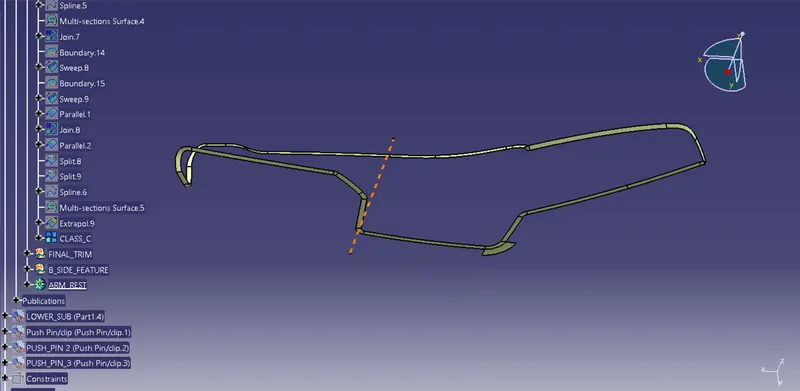
then i trimmed it as show below:
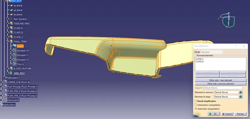
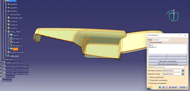
FLANGES - Flanges are the pieces that are required to connect various components. So, on the door armrest and the map pocket, I'll have to build flanges. Following the master section, the measurements and location of the flange are given as input. The flanges were made by me. I started by making the flange on the outside map pocket. I used the curve extraction method to make the flanges. The extraction is shown below:
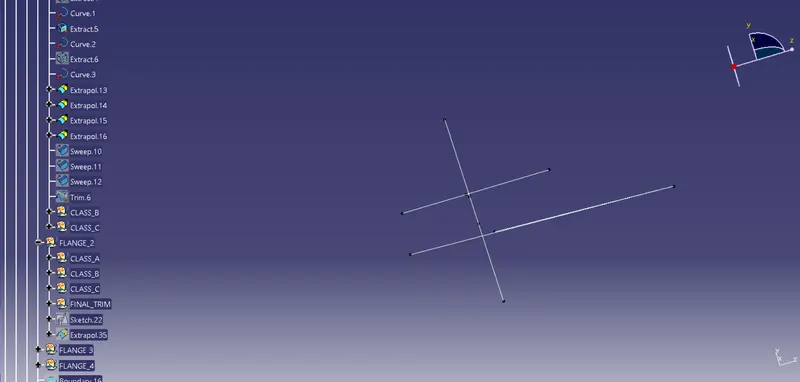
now sweep it
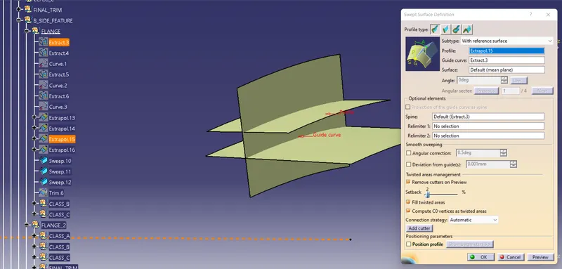
Trim the sweep as shown:
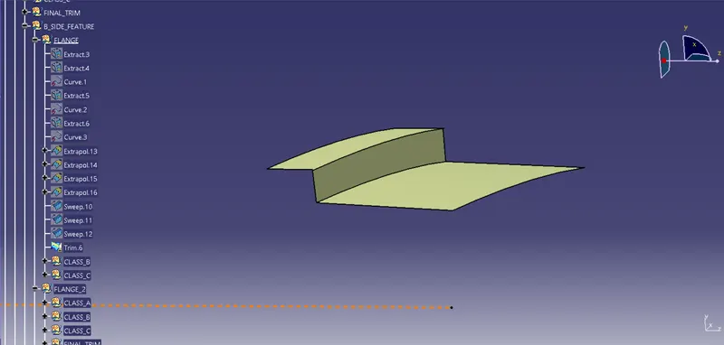
Now take the offset:
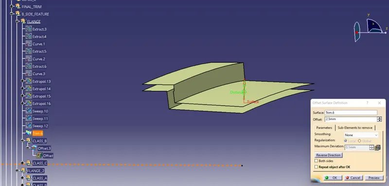
Now creating class C surface withe the swwep as shown:
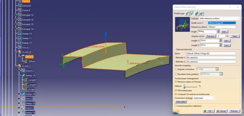
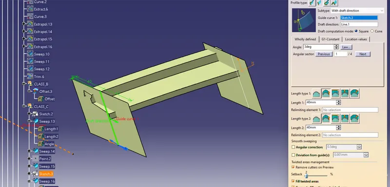
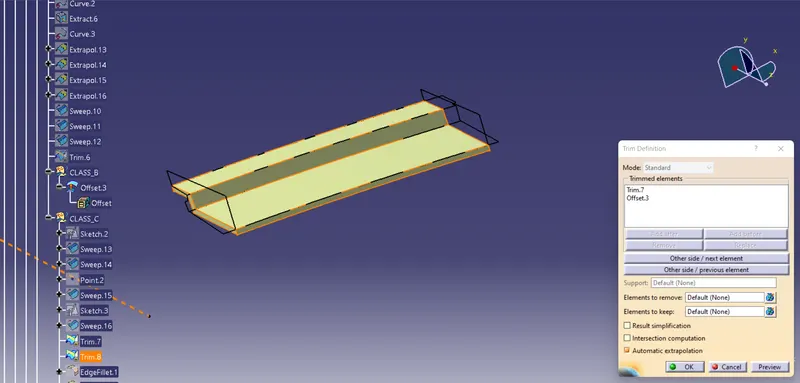
Trimming the class A surface and B with the class C surface.
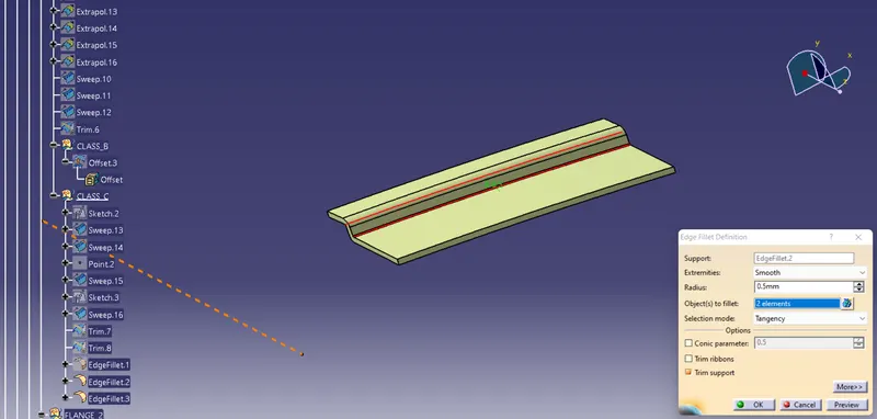
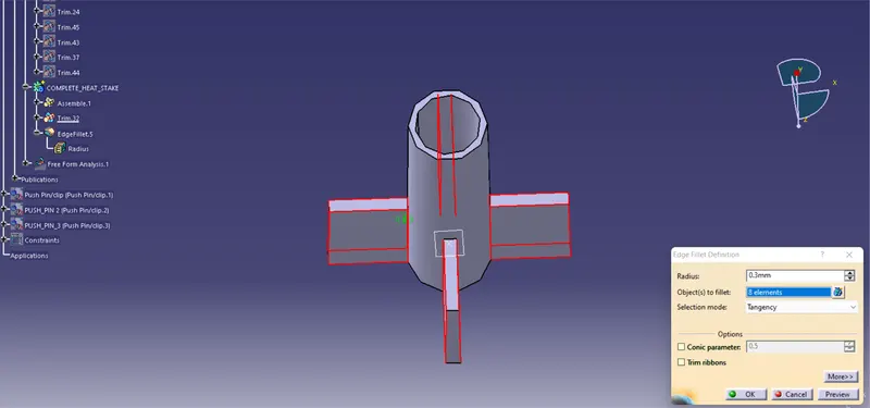
Now edge fillet the surfaces.
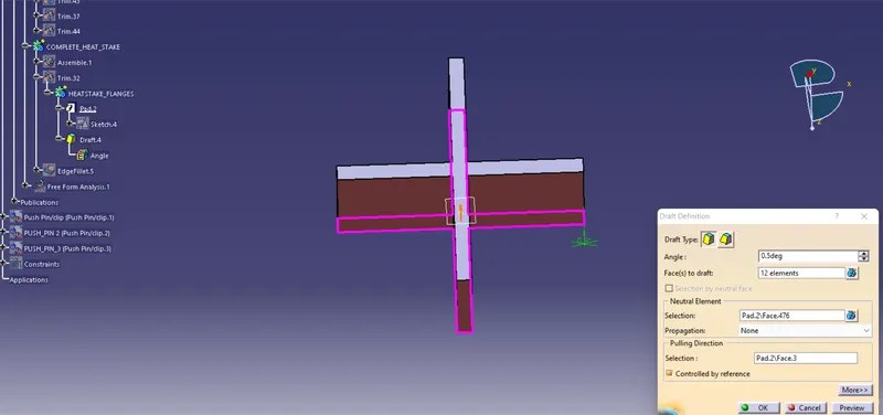
Heat staking - The method of putting two incompatible materials together is known as heat staking, also known as thermoplastic staking. We employ local heating and cooling in heat staking to raise the temperature of plastic components and allow for plastic reformation. This reformation technique can be applied to a wide range of situations. Staking plastic bosses for vehicle door panel assembly to joining PCBs to plastic housings are just a few of the applications. No vibration damage, no particles, the ability to stake metalized coated materials, and the ability to stake in difficult to access or restricted regions are all advantages of this technology.
The head is formed via the gradual melting of plastic under constant pressure. When it comes to staking, finding the correct combination of heat and pressure for the job is crucial.
The advantages of Heat staking are as follows:
1) simplification of the machinery
2) Reduced cost of machinery
3)Multiple fastening points
4) Allows higher density of welds compared to hot air cold form or ultrasonic welding.
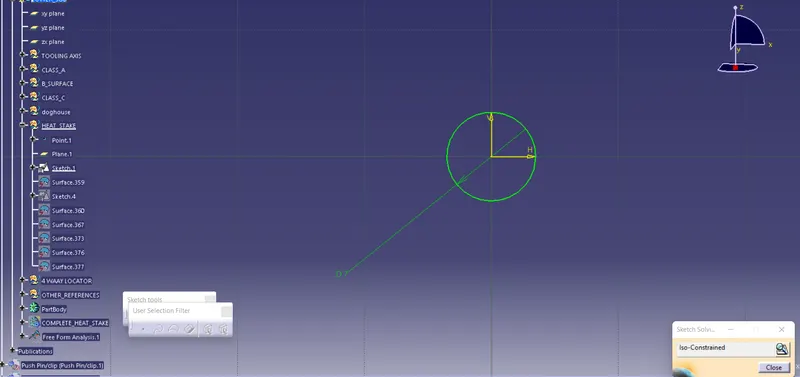
Now creating the heat stakes.
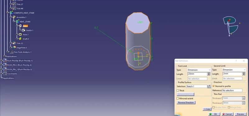
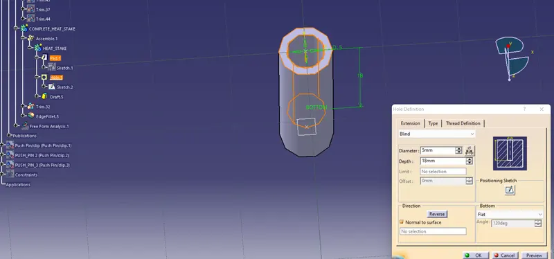
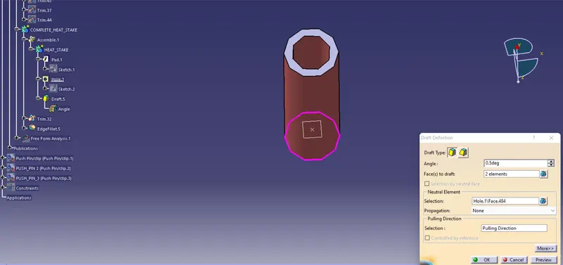
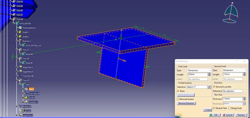
Creating the heatstakes ribs:
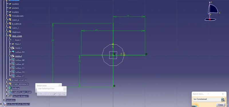
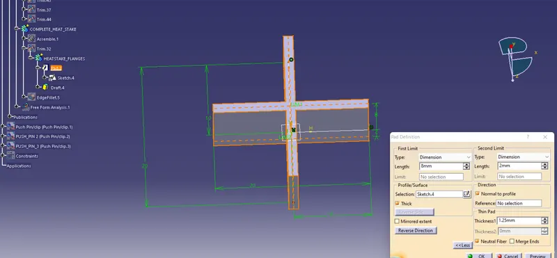
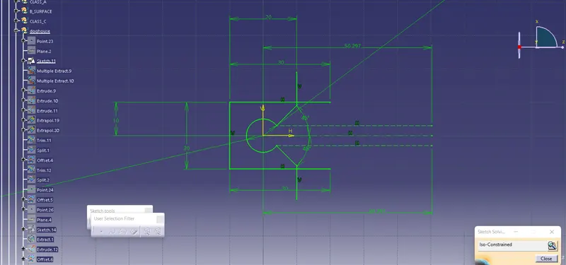
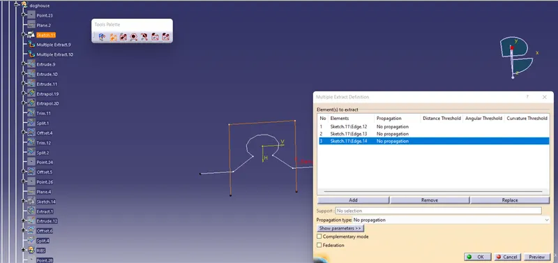
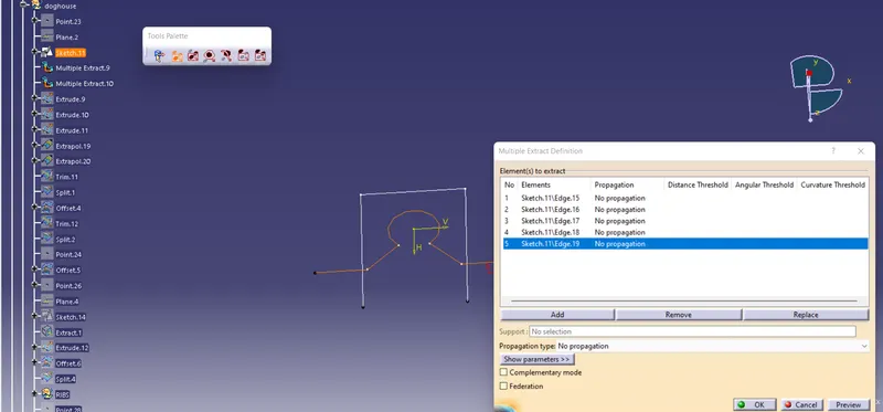
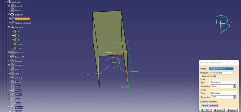
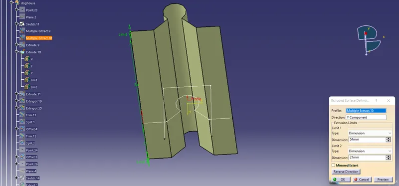
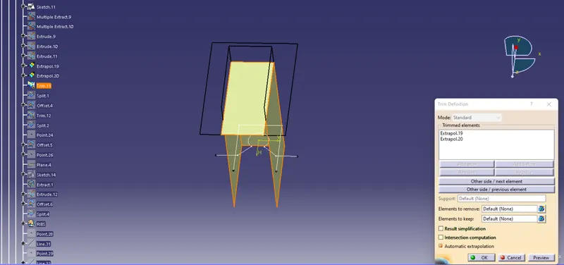
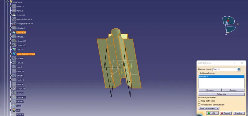
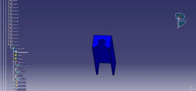
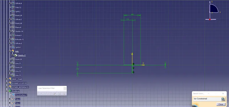
Dog House - The plastic trim design includes a dog home as an engineering feature. As a supplementary component, doghouses are used. Other technical elements, such as snaps, locators, and the like, are sometimes mounded on them to boost their strength. To avoid component breakage during ejection from the mould cavity, dog houses are subjected to draft analysis. B-surface is used to construct the dog home and other engineering components.
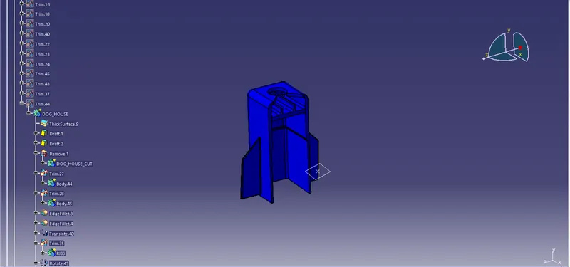
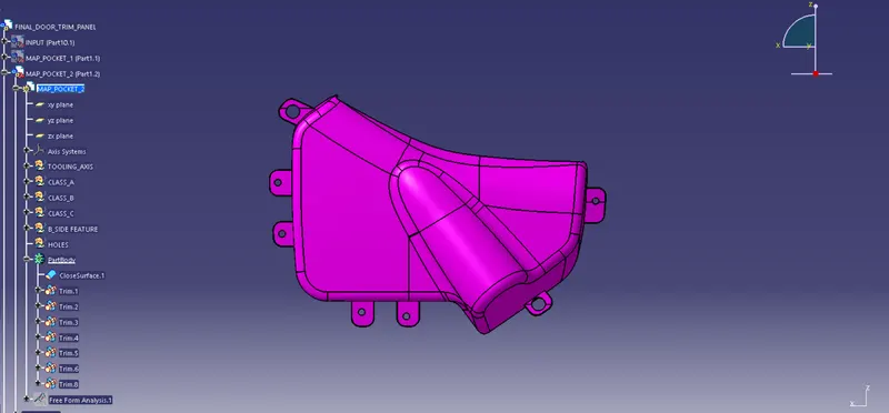
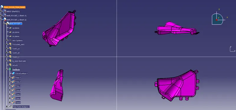
Isometric view, of every part after completion of flanges, dog house and heat stakes.
Lower substrate-
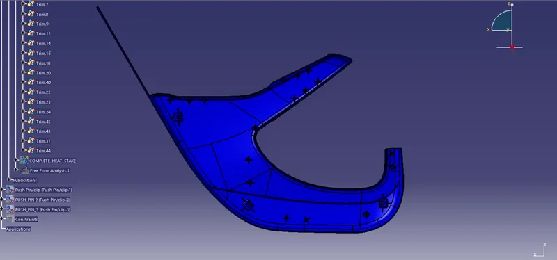
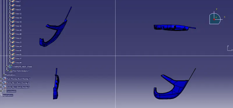
Outer map pocket -
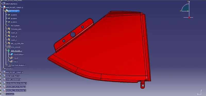
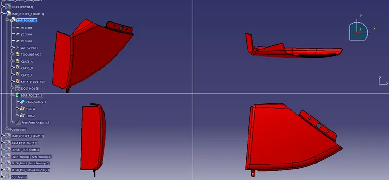
Inner map pocket-
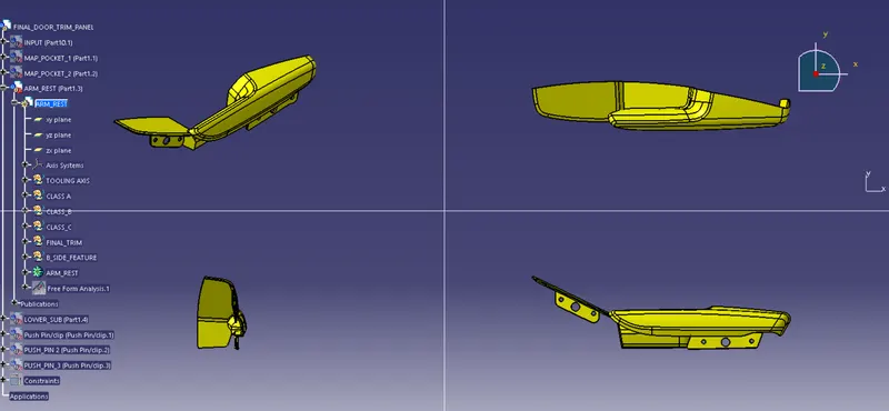
Arm rest-
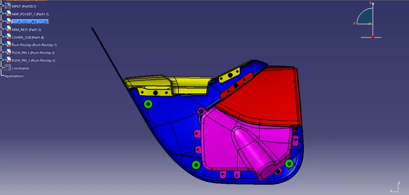
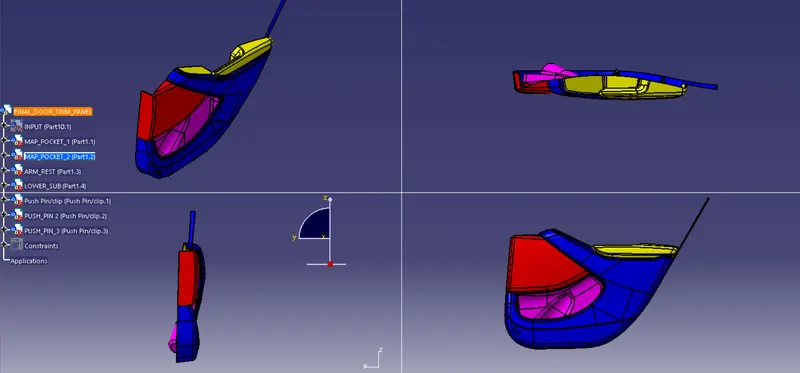
Final output
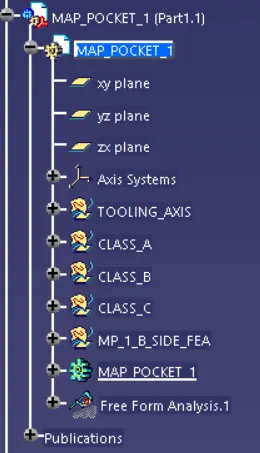
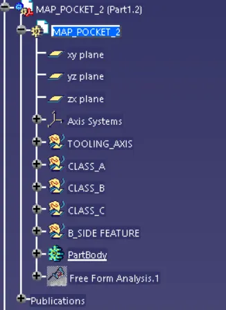
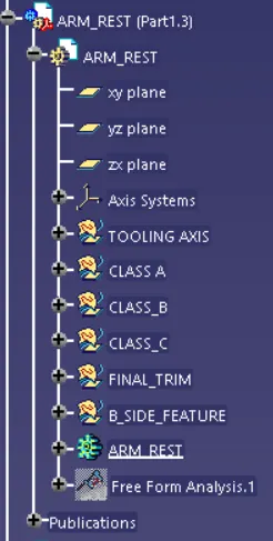
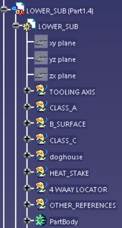
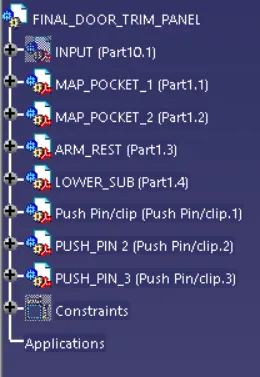
Geometrical sets -
Conclusion: Concluding the above analysis of creation of the Door Trim Panel along with engeneering features using the master section given as input and draft analysis has also been performed on the component.