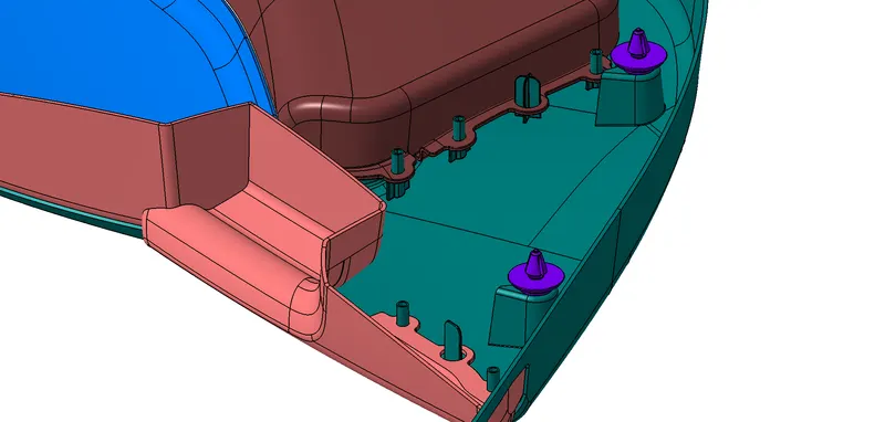
Week 11 - Final project
Development of a Door Trim panel
Week 11 - Final project
Objective:
To develop the Door trim panel from the given Class A surfaces by creating solid bodies and adding adequate attachment and special features with the required draft values for proper manufacturability.
Process:
Creation of Tooling-axis and Initial Draft analysis
- Tooling axis or Pulling Line is the axis along which the core and cavity opens and closes. It is very important to define the tooling axis in the first step while designing a component as it is the main component which helps us to run draft analysis on class A at initial stage to see if we can move ahead. The tooling axis is also the direction along which Class c surface and the draft to the components are given.
- A tooling axis along Y-direction was created to behave as the tooling direction.
- A side core tooling axis was created for the Door arm Rest component and a lifter axis for the doghouses.
- Draft analysis was performed on the provided Class A surfaces. This is done so that any components which fail majorly for draft values can be sent back for revision and reworking of the Class A surface.
Draft Analysis
- The material mode was first selected in the view customization parameters. This setting is required for the Draft Analysis tool.
- The compass was used to create the draft direction for the component.
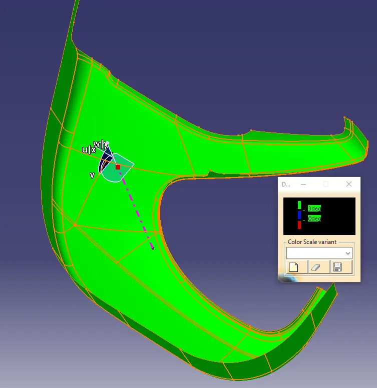
- The elements to be analysed were chosen and the Colour Scale displays the range of draft angles within the component. The standard maximum allowed draft angle of 3 degrees for plastic components was entered in.
- The given model passed for draft analysis.The running point option was used to check specific surfaces within the component which may seem parallel or almost parallel to the tooling axis.
- The initial Draft Analysis performed on the provided Class A surfaces even before closed bodies are created.
Draft Analysis on Various Class A surfaces
Lower Substrate:
Fully passes the Draft Analysis test. Toolable component
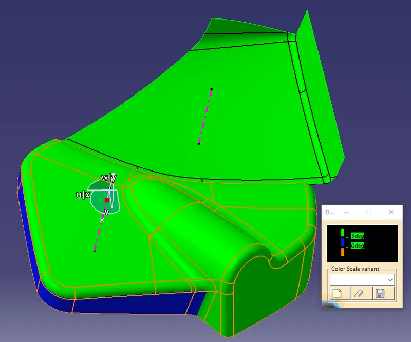
Map Pocket and Bottle Holder:
Mostly passes the Draft Analysis except for few faces. Toolable component since even failing faces have a small draft value.
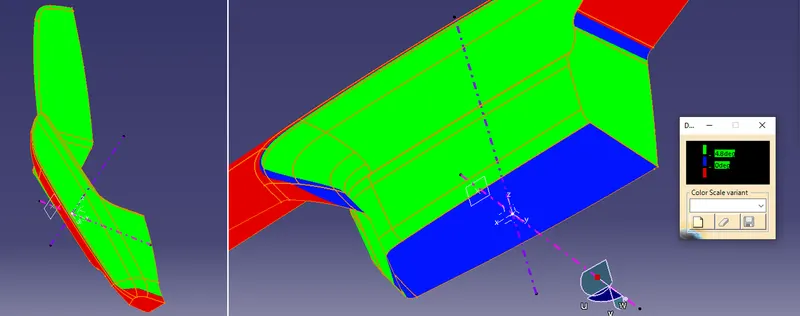
Arm Rest:
Fails Draft Analysis. Non-toolable component. Although the Class A surface fails the draft analysis, the modelling was carried on since it does not affect the objective of this project.
The provided Class A surface has errors in it and should ideally be sent back to the Class A design team for reworking.
Creation of Solid body from the provided Class A surfaces:
Class B surface creation
Most of the Class-B surfaces were created by offseting the Class A surface to a distance of 2.5mm (which is the nominal thickness obtained from the provided Master section) on the inner side.
Class C surface creation
Class C surface is swept along the boundary of the Class A at a perpendicular angle with respect to the surface. In cases where the C surface comes in contact with the tool, the Class A surface is swept with respect to the tooling axis direction at a draft angle of 3 degrees.
The created surfaces were then trimmed or joined together to form closed surfaces of the components.
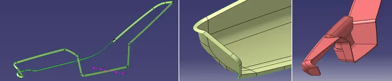
Arm Rest

Lower substrate

Map Pocket
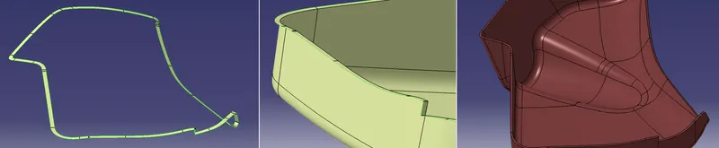
Bottle Holder
Creation of Attachments and Special Features:
Flanges based on Master Section:
The master section was used as a reference to create some of the flanges on the components.
The surfaces were Swept, Trimmed and Closed before a solid body was made out of them.

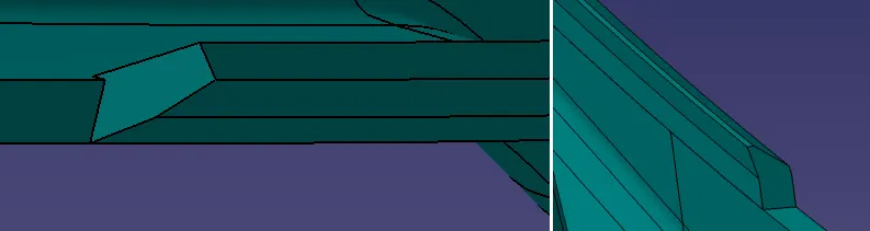
Other Flanges:
- The creation of the other flanges were based on an original strategy since the master section lacked reference.
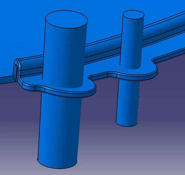
- The flanges were made around the Bottle Holder and Map pocket in order to support the heat stakes and locators which would be modelled later.
- The flanges had a thickness of 2.5mm and appropriate chamfers and fillets were provided.
- Holes were created by creating solid bodies with diameter corresponding to the required diameter for heat and then using Boolean remove.
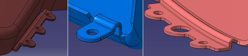
Flanges
Heat Stakes with Ribs:
Heat staking is the process to attach two separate components together by melting the base plastic material into a shape that will hold the secondary component. It’s a permanent attachment method that does not require any additional material such as an adhesive or a solvent to make the permanent bond. The only addition is the heat applied to melt the plastic and a tool to shape the plastic to form the mechanical connection.
Heat staking can be done with a precise and rapid operation that also offers repeatable results every cycle. Manufacturing machine can be developed to complete multiple heat staking operations at once to decrease cycle time. The stakes don’t have to be parallel which makes the design options limitless.
Heat staking is a great option that is comparable in strength and durability to other operations involving secondary fasteners without extra cost. These connections can also resist corrosion in harsh environments.
The Heat stakes for this model were created utilizing standard Plastic design rules. The heat stakes were designed with an outer diameter of 7mm and an inner diamter of 5mm. The ribs are provided for strength and have a thickness of 1mm.
The heights of the ribs were maintained between 8-10mm.
Ribs provide an economical stiffness to the component without increasing overall wall thickness. They also facilitate:
- Locating and arresting components of an assembly
- Providing alignment in mating parts
- Acting as stops or guides for mechanisms
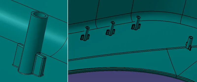
4-way and 2-way Locators:
A 2-way locating pin restricts motion along 1 axis (or 2 degrees of Freedom), like a round pin in a slot. Likewise, a 4-way pin restricts 4 degrees of freedom along 2 axes. A round locating pin located concentrically in a hole is a common application of a 4-way pin, and helps to further secure the piece.
The 4-way Locators have a length of 7.5mm on one side and the 2-way locators are 15mm in length. They have a thickness of 1.5mm.
A single 4-way locator and a single 2-way locator were provided for each component to secure them to the lower substrate.
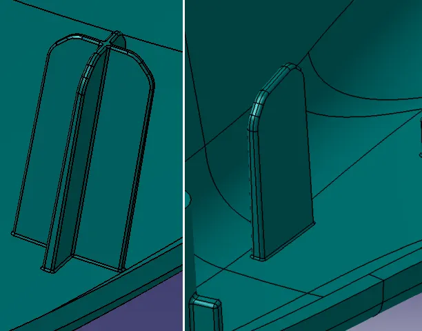
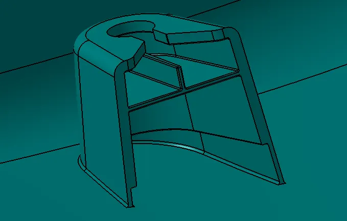
Doghouses:
Dog house is an engineering feature used in plastic trim design. Dog houses are used as supporting feature. Sometimes other engineering features like snaps; locators etc. are mounded on them to increase their strength. Dog houses are subjected to draft analysis to prevent breakage of the component during ejection from mould cavity. Dog house and other engineering components are built on B-surface. 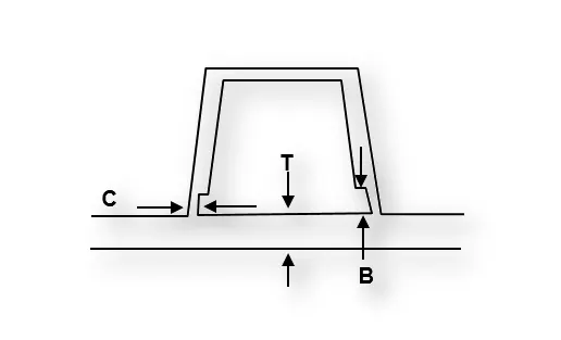
"C" is where the doghouse contacts the backside of the surface
- Doghouse wall thickness at the intersection of the part wall ( C ) should be 40% or less than the main wall stock ( T ).
- Height of ( B ) should be between 3.0 – 6.0 mm
"Coring" or material removal from the bottom portion of the doghouse was done to avoid sink marks during manufacture.
Ribs were provided for strengthening the doghouse and to support the push clip.
Push Clips:
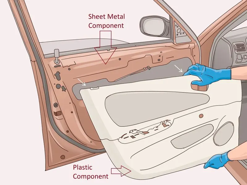
Push clips were obtained from an already created PartFile. The push clips are provided to attach the Plastic Door Trim to the Sheet metal part of the Door assembly.
Push Clips were assembled into their appropriate positions on the doghouse. The doghouses help to support and elevate the position of the Push Clips.
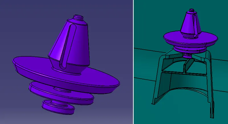
The many attachments and special features were then translated point-point to strategically placed locations around the Lower substrate.
Final Draft Analysis:
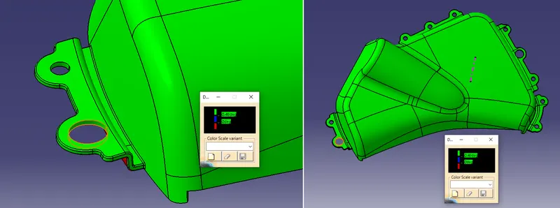
Bottle Holder
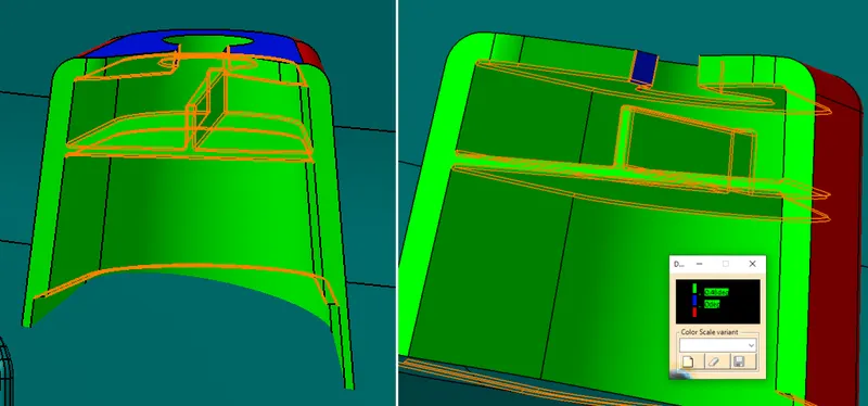
Doghouse Draft Analysis for the Lifter Pulling line
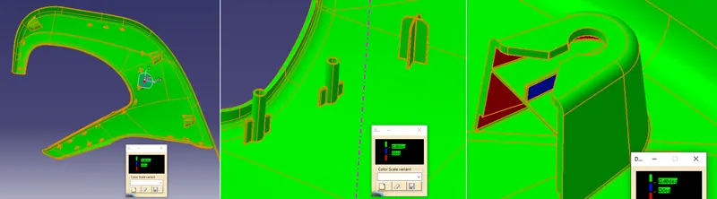
Lower Subtrate and features on the lower substrate
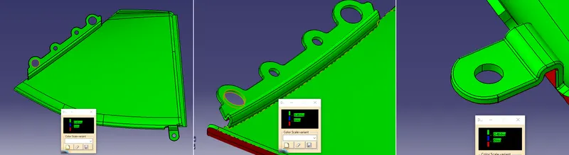
Map Pocket and its flanges

Arm Rest
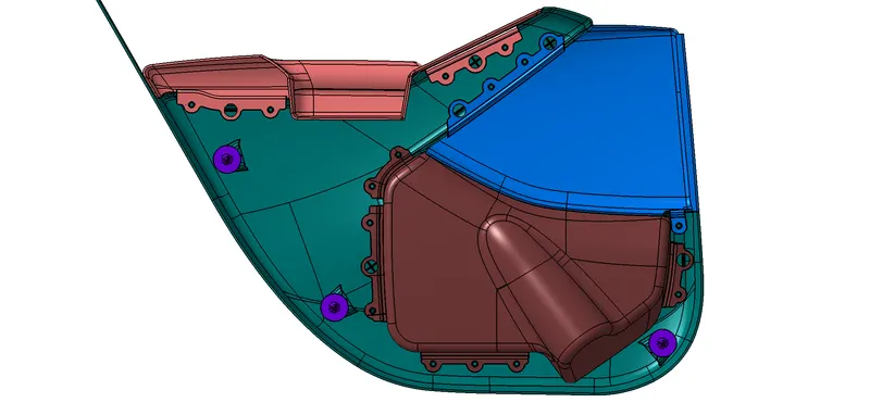
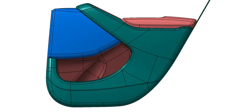
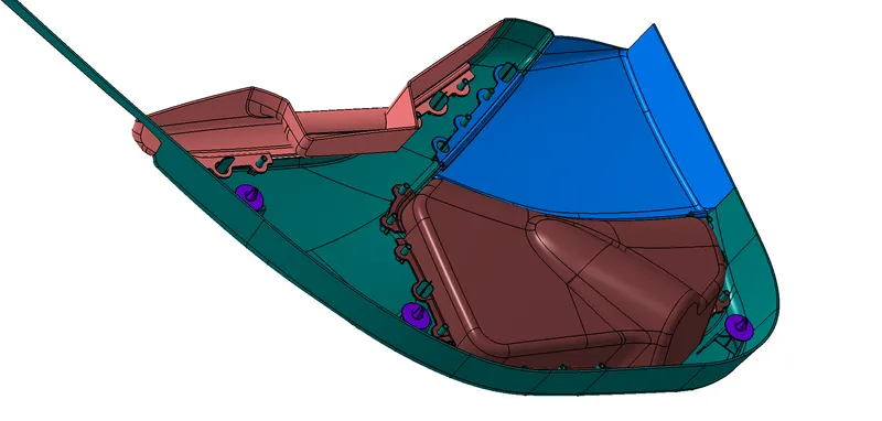
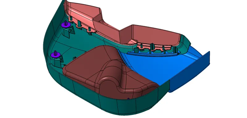
Screenshots of the Final CAD Image: