Week 11 - Final project
Door Trim Panel
Introduction:
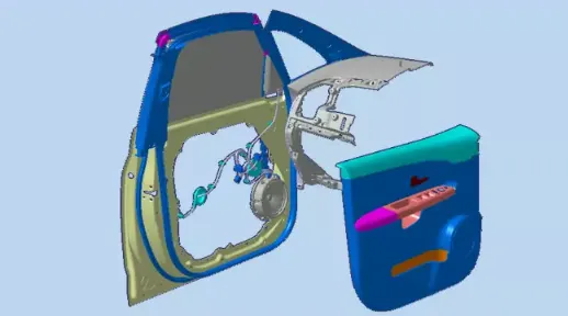
The Door Trim is the Plastic component serves as the interface between the sheet metal part of the door panel. The trim panel is placed inside the automobile. Different parts such as arm rest, Switch Bezel, Map Pocket and Substrate panels are included in this plastic trim panels. The design of the trim panel differs with OEM companies. each companies have thier own aesthetic design features. Trim panel houses the Central Locking system,Speaker, Power window control and its electrical wirings and circuits. The design constraints also changes with functionality of each afrorementioned systems. The above fig shows the Assembly view of Sheet metal and plastic door trim substrate.
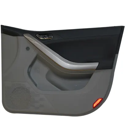
The Different components of door trim panel are the following;
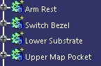
1. Arm Rest
2. Switch Bezel
3. Lower Substrate
4. Lower Map Holder
5. Upper Map Pocket
Aim:
Design the Door trim panel including the components mentioned above. Surfaces of different componenets are provided with master sections, The different sections has to be designed seperatly using CATIA V5 with necessary engineering feature such as Heat stakes, doghouses and the different parts are assembled accordingly.
Tools used:
Class A, B & C surfaces are created via Shape>Generative Shape design option


Parts are created via Mechanical design >Part Design


Arm Rest
Class A surface of Arm rest is provided, the first step is to check for any defects or gaps in surface by using the boundary 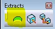 Option, if any defects they need to be rectified before proceeding futher.
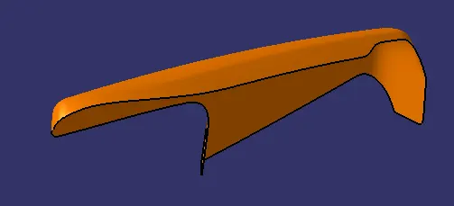
The next step is the tooling axis creation, the created axis should be clearing class a surface.
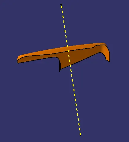
Once Class A & Tooling axis creation is done an offset of 2.5mm is created which will be the class B surface.
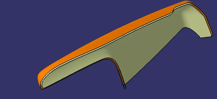
The next step is class C creation for that the class B is extrapolated outside with a dimension of 5mm and a boundary is created with class a which is sweeped to obtain class C surface.
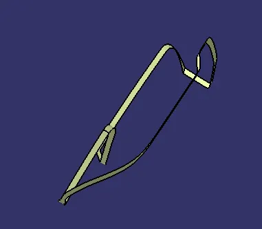
Once class C is created theay are trimmed with the extrapolated class B to obtain the final trim of Arm Rest surface.
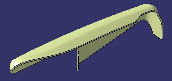
Once surface is created part design is selected to create the part body. Inside part body> Close Surface tool is selected to create the Arm Rest Body. Once Arm Rest body is created it is subjected to draft Analysis with 0.5 deg Draft.
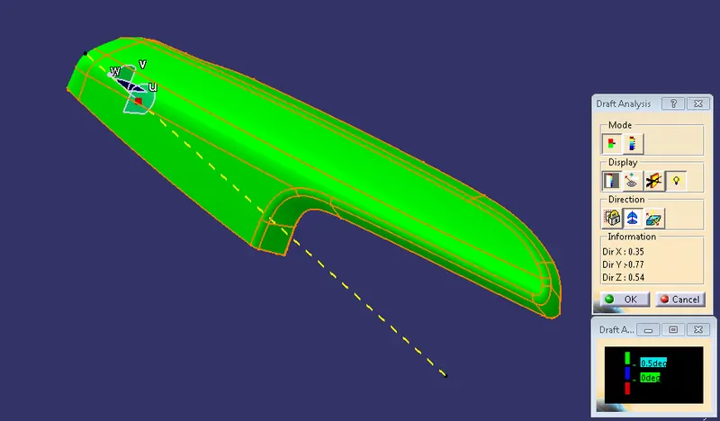
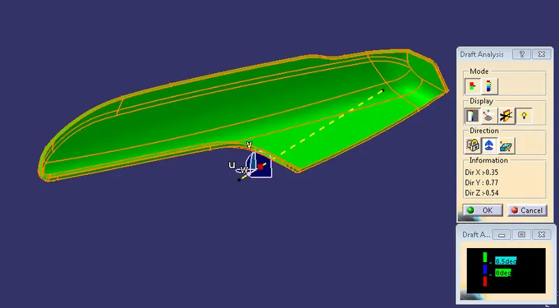
Surface highlighted in green shows the part has a positive draft.
Once Part is created Flanges and Heat Stakes are created using the surface option and they are thickned using part tool. Once a flange is created they can copy pasted no of required times and the pasted copies can be translated accordingly via points or co-ordinates and they can be union trimmed or added along the main flange.
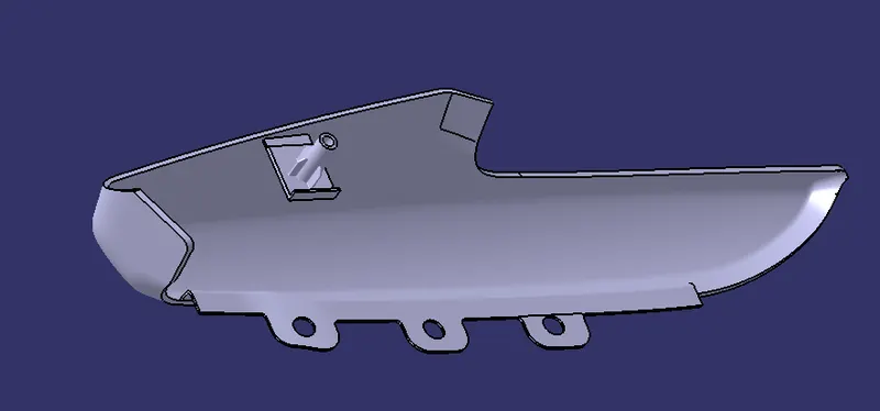
0.5 deg draft is provided to the heat stakes.
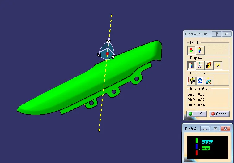
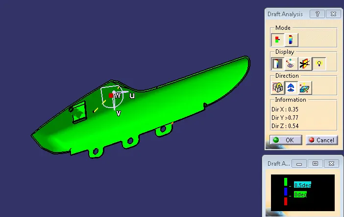
Switch Bezel
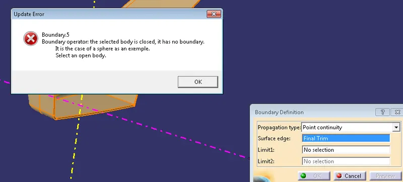
The Provided class A is checked for any boundaries
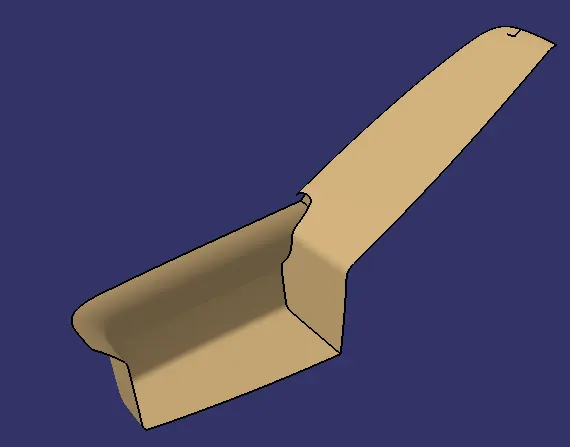
The next step is to create the tooling axis. A point is created at the centre of gravity of the surface and a line created using line command will be the tooling axis. Once tooling axis is created 2.5mm offset is created which will be the class b surface.
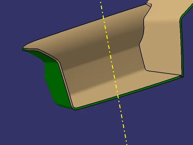
Since the tooling axis wont clear all sides another side core axis is created.
Once Axes are created Class B surface is extrapolated and a surface is swept from the class A boundary such that they intersect, the surface swept would be with reference to tooling axis
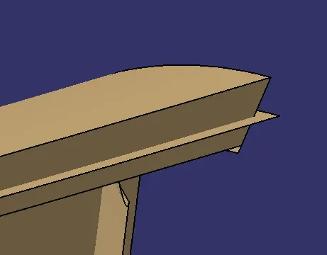
The two surfaces are trimmed to obtain the final trim.
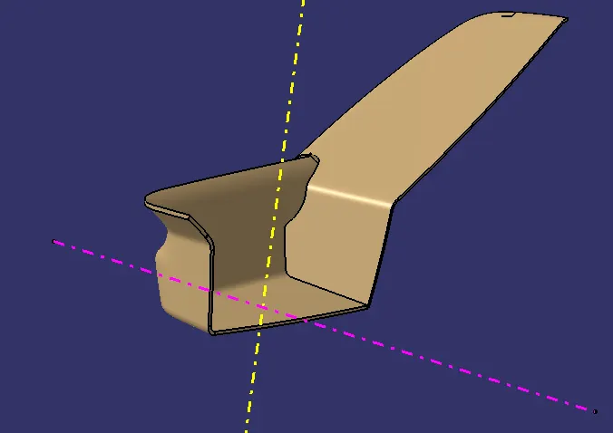
Once the final trim is created before creating the part we can check for any boundaries or gaps in the trim using the boundary tool.
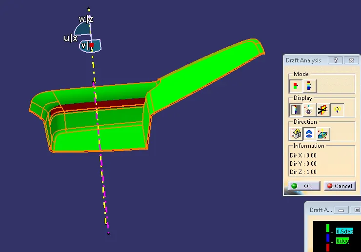
Once the trim is obtained part is created and they are subjected to draft analysis. Analysis has to be done through main and side core axis using the compass tool.
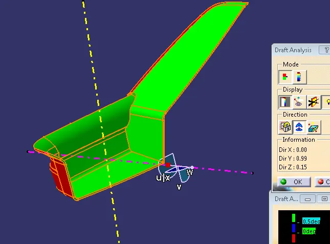
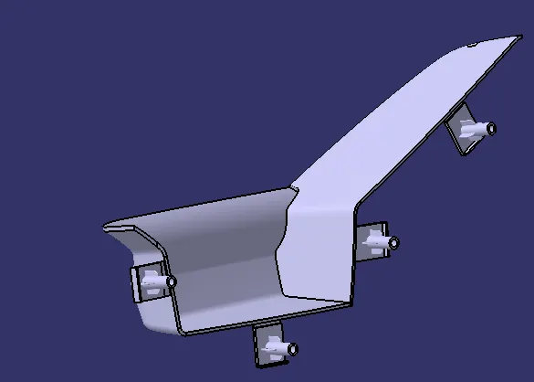
After draft analysis on the part engineering features such as heat stakes and flanges are created. They can be created as a single part and translated to the required points or co-ordinates. The heat stakes are drafted with 0.5 deg with respect to the side core axis.
Lower Substrate
Class A is checked for any boundary defects and gaps once clear proceed to tooling axis creation by creating a point at the centre region of the lower substrate part. Once tooling axis is created proceed to class b creation by offsetting 2.5mm from class a surface.
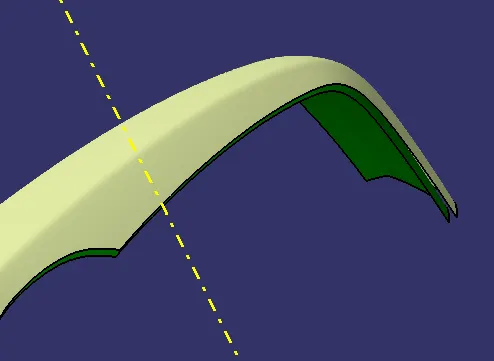
Once class b is created a seperate flange has to be created as per the master section. A boundary is created at the required end and a surface is swept as per master section.
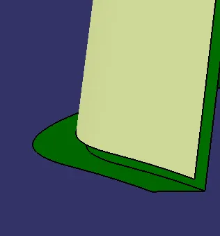
Once Class b creation is done next step is extrapolating class b and sweeping surface from class a with respect to tooling axis to create the final trim of Lower substrate. Once final trim is obtained the part option is selected to create the surface into part and once done they are subjected to draft analysis to check the draft clearance with tooling axis.
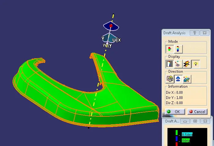
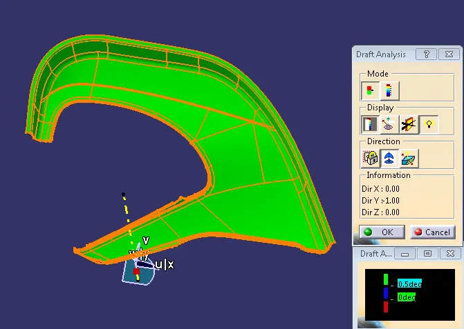
Once done with draft analysis, proceed to doghouse and heat stake creation. while creating doghouse certain design rules has to be followed.
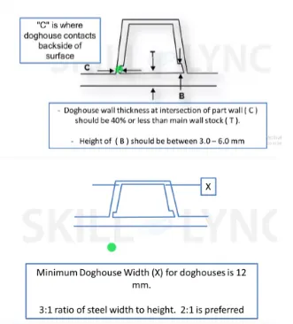
A seperate side core axis is created so as to provide necessary draft to the inner walls of the doghouse. Once they are created and translated to required regions they can be union trimmed with the Lower substrate part.
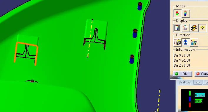
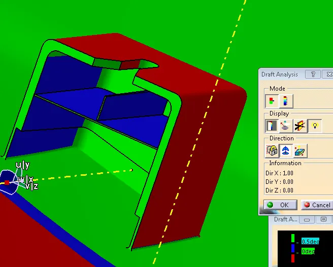
Flanges are created as per the master section. It is at this flange were the upper map holder clips over to join with the panel.
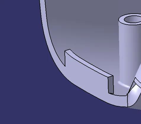
Lower Map Holder
The same process is followed in the creation of lower map holer.
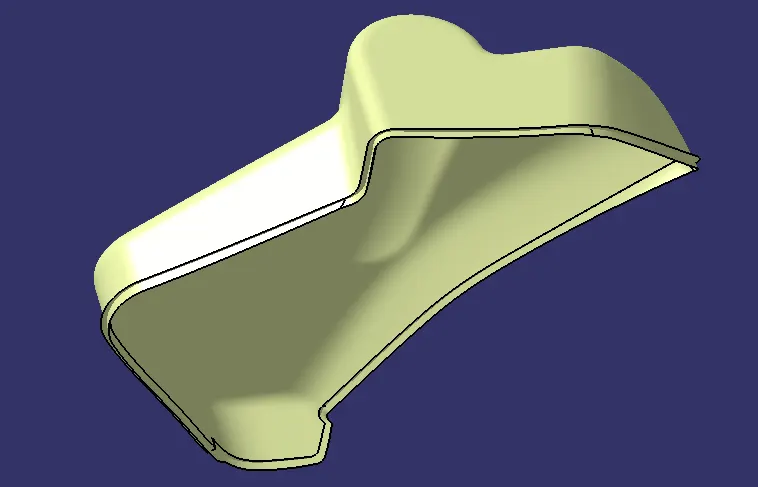
Class A and b surfaces are extrapolated for trimming. Tooling axis is created from centre point of the class a surface.
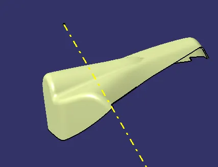
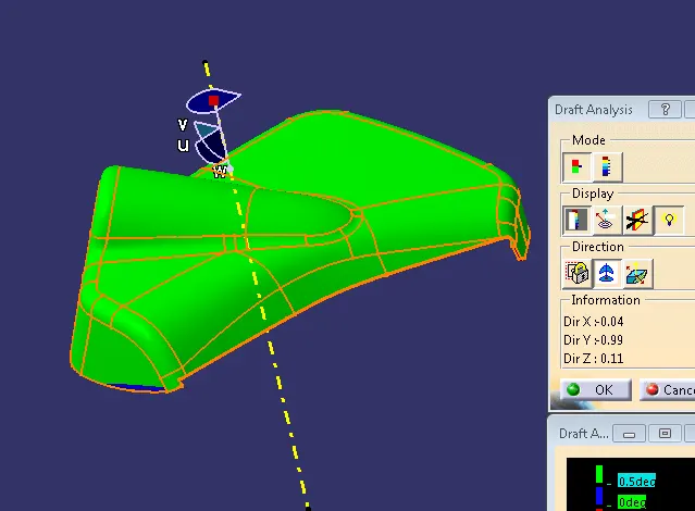
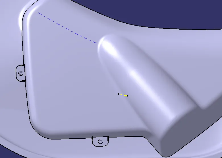
Once the trim is created the surface can be closed to a part and then do draft analysis on the same. The compass tool is locked on the map holder tooling axis and the surface is selected to provide draft analysis which is shown with colour code with green denoting positive draft, blue zero and red with negative draft. this colour coding helps to identify areas that are not clearing the tooling axis.
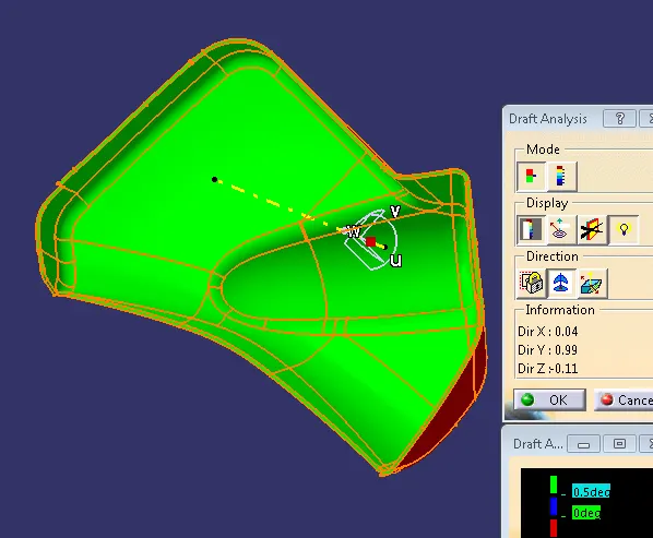
In addition to that flanges are created for coupling with lower substrate heat stakes. These are made for heat staking in which the parts will be joined.
Upper Map Pocket
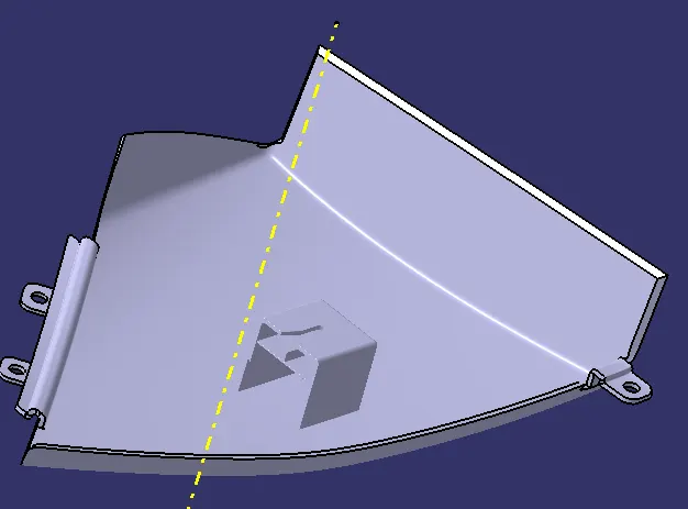
In Upper Map pocket apart from part creation extra Flanges are also created to accomodate the heat stakes.
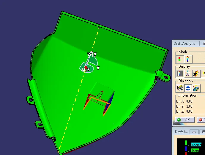
Draft Analysis shows positive draft on the created part body.
Design considerations to be followed
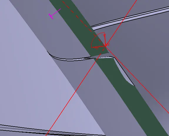
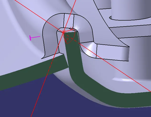
After creating once part before proceeding to next one always make sure the adjoining part edges are not intersecting. we can take a section at the joining edges of part to check for any intersection or deviations. This kind of defects can be kept in check during the class c creation. Make sure the created sweep does not intersect with the neighbouring part.
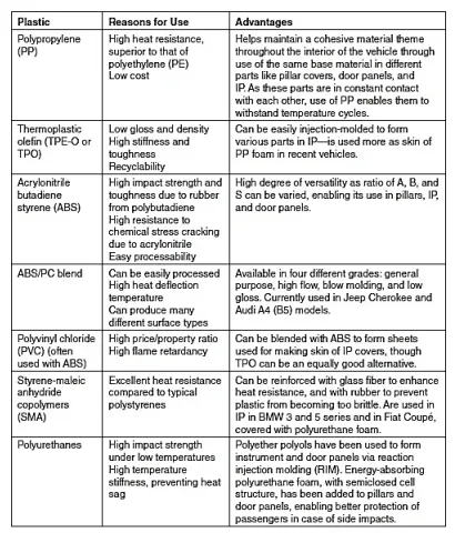
Material Selection
Thermoplastic materials are used in the different parts. For cost effective production foam based products are used. List of materials that can be used are follows;
Attachment Strategy used
Parts are attached using heat staking process. It is a pulsed heat process used to join one or more parts, this process will deform the heat stake for a period of time once the part is deformed it is coupled with flanges to fix them. Usually thermoplatic materials such as Polystyrene, Polucarbonate, nylon are used. The main advantage of this process is that both similar and disssimlar parts can be joined together. In case of switch bezel a more matte finish material is used it still can be attached to other parts via heat staking.
Door Trim Design
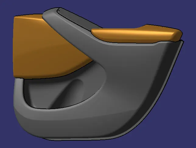
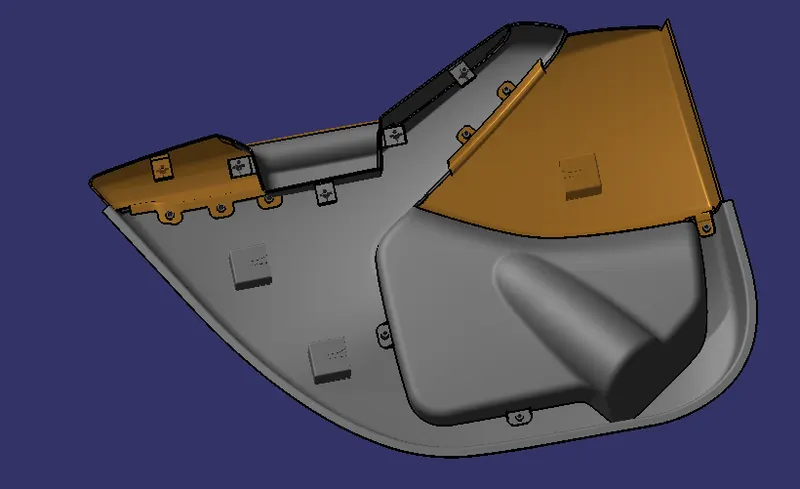
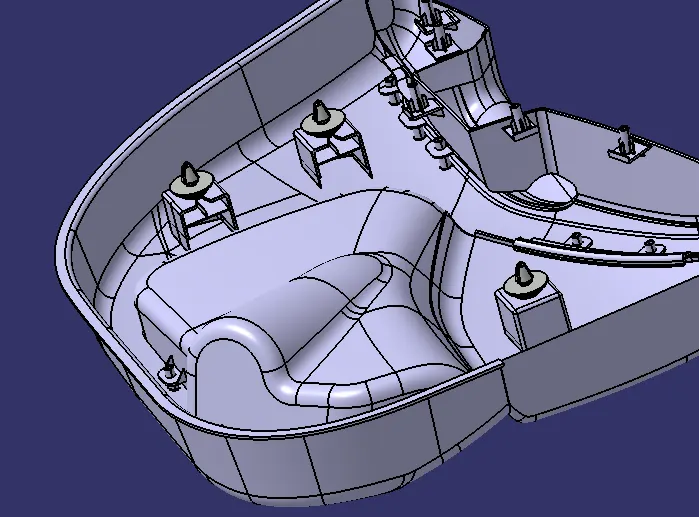
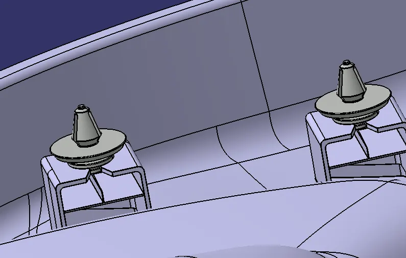
Door Trim with Push pin
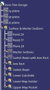
Tree Structure