Week 8 - Challenge 1 - Draft Analysis on a Fan Cover
Draft Analysis on a Fan Cover
Draft Angle:
Draft Angle or Engineering Draft is the degrees of taper provided to the part perpendicular to the parting line. It is very important to provide a necessary draft as it depends on the outer structural integrity of the molded part during the ejection process. If the product is formed onto a female or negative mold, it shrinks away from the mold sidewalls. As a result, true female or negative products can be thermoformed with vertical walls having zero draft angles. By providing a Taper the mold will be easier to remove.
Tooling Axis Creation:
Once the Class is checked for any unwanted openings or edges a dummy axis is created just for reference although its not mandatory. Using the Intersection tool Intersection sketch are created in the XZ and YZ plane of the product.
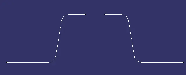
Centre axis is obtained by extending lines from both sides of the sketch and joining them by Bisceting Option.
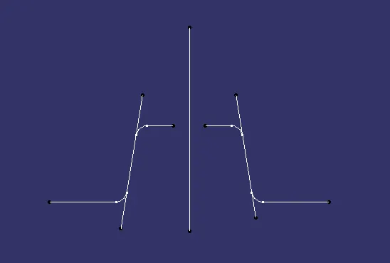
The Above mentioned process is performed in Intersection sketches in both XZ and YZ were the Z direction is opted for tooling axis. Once two axes are created they are bisected to create the Tooling Axis.
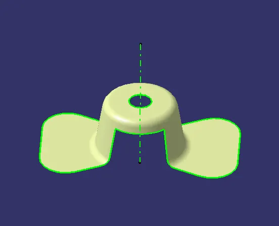
Draft Analysis:
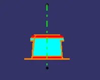
This is the next step after tooling axis creation. By going to Insert and selecting Feature Draft analysis. Once the Draft Analysis Tap apperas the Tooling axis is locked using the compass tool and lock it via lock tool and the draft is show with a draft angle Colour code reference. The below image shows that the prouct has a 3 degree draft angle from the tooling axis. Red colour code denote o draft and blue represent negative draft.
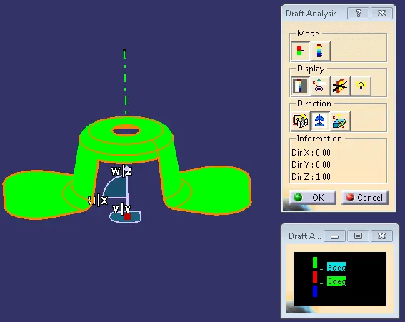
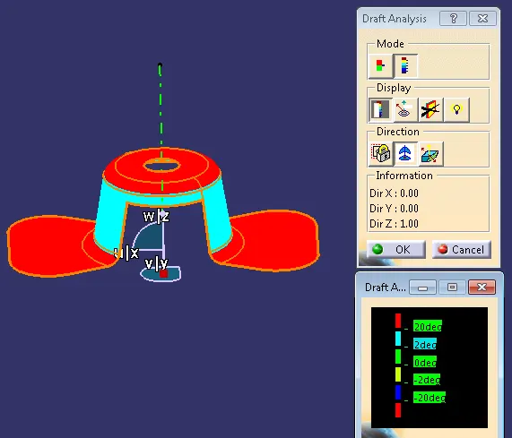
Full Analysis Mode shows diffrent draft with the repective colour code.
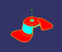
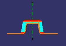
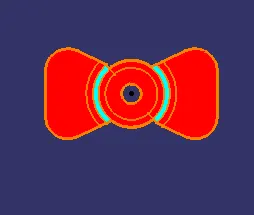
Various Orientation of the model.
Tree Structure:
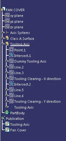
Toolig Axis and Fan cover are published in the tree structure so that they can be easily identifed and be able to acess.