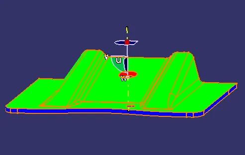
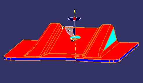
Week 8 - Challenge 2 - Base Bracket Design
Draft Analysis on Base Bracket Design
The first Stage is Check for any gaps or boundaries in the Provided surface and Once it is clear the surfaces are joined together to form the Class A surface. Class A surface is outer surface which is supposed to be aesthetically appealing.
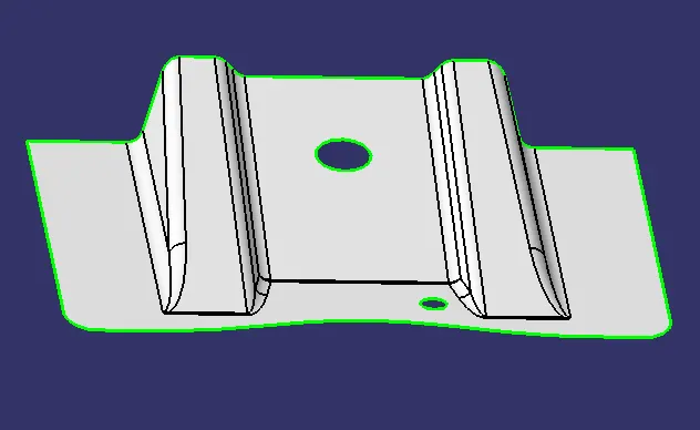
Once the Class A Surface is created the next step is to create the tooling axis. Tooling axis is the perpendular line that clears the Class A surface which helps to denote and define the draft in the surface. Z direction is taken as the tooling axis since it is the feasible direction which can clear the class A surface.
A Point is created at the hole rregion of the class a and line is created which is denoted as the dummy axis which is created for refrence. After this step an intersection boundary is created in the YZ plane using the intersection tool. After this the points on the intersection boundary are extended to form lines which are bisected using the line tool to get the tooling axis of Class A surface.
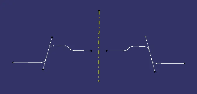
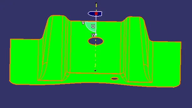
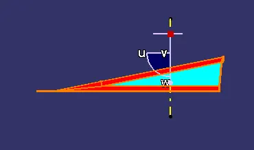
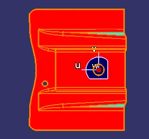
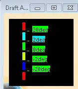
Once Tooling Axis is created click on Insert> Anlaysis> Feature Draft Analysis Option. We get a draft analysis Pop up window, using the compass option we can select the draft direction after locking it and clicking on the surface we will get the draft analysis with the colour code denoting the angle of draft. As per the below image our surface have a 3 degree draft. If the surface denotes red then the surace has a zero draft, if denoted as blue then the surface has negative draft with respect to the tooling axis.
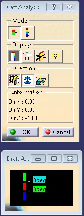
There is another option called full analysis mode which will provide the detailed draft angle of the surface with a bit more detailed range of colour code.
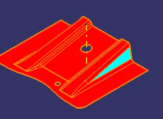
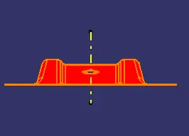
Once Draft Analysis is done next step is to create Class B and Class C surface to give thickness to the Class A, The thickness taken is 2.5mm. Class B Surface creation is approched by creating the 2 seperate ribs and base surface and trimming the same to obtain the required surface. Ribs are created by offsetting the extracted surface and they are extrapolated and trimmed. Once the ribs are created the extrated surface from the base is offsetted and trimmed with ribs to obtain the final Class B surface. In the below Image the surface higlighted in pink is the obtained Class B.
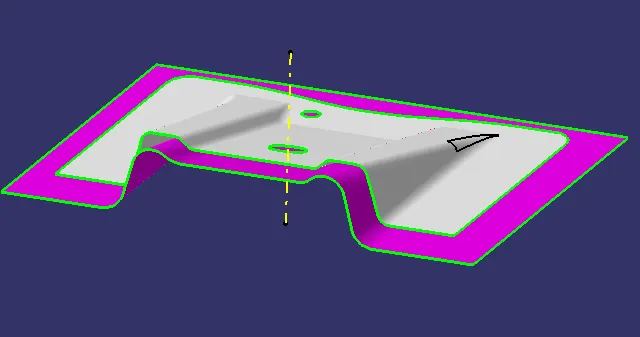
While providing the fillet to class B it is made sure that the offset distance 2.5mm is added to the fillet radius of 3mm.
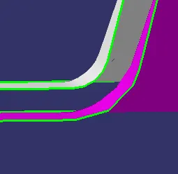
The next Step is the creation of Class C. A boundary is created outside the class a using boundary tool after this using sweep option with the refernce to tooling axis the class C surface is created. The surface highlighted in brown is the created class C.
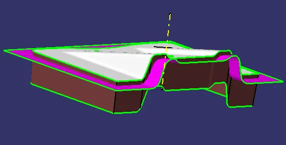
Class C surface i strimmed with the other suraces to get the final model, and they are made into part body via colse tool.

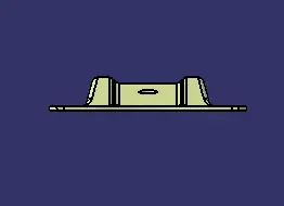
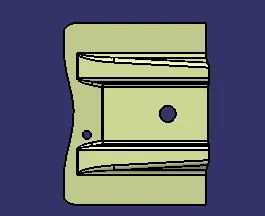
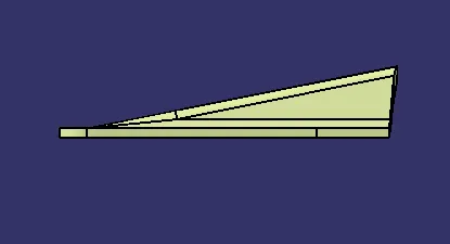
Drfat Analysis of Fiinal Product: